
V.2.0.9305
Modeling
- Some of you reported that the Measure tool did not show distance when you tried to measure a face to an origin plane. Sorry about this glitch; this has been fixed.
Electronics
- carl.j.barker was working on his P3D CB when he encountered an issue where Fusion 360 failed to get the 3D package for IC_Logic > 74*32 > 74LS32N. Now the packages are retrieved without a hitch.
Manufacture
- eburke197 reported to us that after having imported the Harvey tool catalog to his tool library and copied/pasted the tool he need into his milling library, he ran into a “failed to select tool operation” error when he wanted to use the tool in a operation. We found some wonkiness under the hood and sorted it out. Now it should work flawlessly.
- We fixed a selection issue where Sketch entities, among other things, became selectable when defining a WCS Orientation in a Setup, even though the Sketch parent folder and child entities have been explicitly turned off.
Additive
- Rapid moves are now available again for additive strategies and 3D prints to ensure that the print quality is optimized.
API
- pludikar told us about an issue with our API and where if the event handler references get leaked, they can adversely still have “old code” handlers registered and handling events. This required them to restart Fusion 360 to clear them, which can be annoying and cumbersome. Now, all old event handlers owned by a script will be removed automatically when that script is stopped.
V2.0.9144
- We fixed a bug that was preventing the post security prompt dialog from being shown at the right time. We crushed this bug and now it’s back in business.
- There was a weird issue that was causing Fusion 360 to become unstable when you tried to Save As. We looked under the hood and tightened a few bolts; now it should run smoother.
- Some of you were also experience instability when you tried to open some of your designs. We found that refreshing the data panel sometimes triggered a weird occurrence in the code, so we cleaned that up as well.
V.2.0.9142
This product update brings you the following feature highlights:
Revamped Sketch > Text with Text on Path in Sketching
Custom Footprint Pads in Electronics
Recommended and Favorite outcome iterations in Generative Design
Remote Constraints and Moment in Simulation
All-level Parts Lists, Hole & Thread Notes in Drawings
Manufacturing Model, Grooving Tools in Profile Finishing in Manufacture
Table of Contents [hide]
Usability
New! Access to design version history from the browser
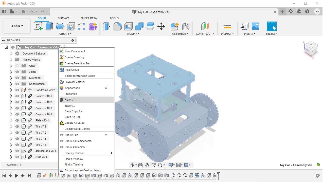
You now have the ability to access your design version history right from the component in the browser. It currently supports both the root component and inserted components. This is the first of many changes you will see coming to Fusion 360 that bridge the gap between desktop software and this cloud-based data environment.
Learn more about the new version history experience
Improved! Saving changes and Milestones at the part level
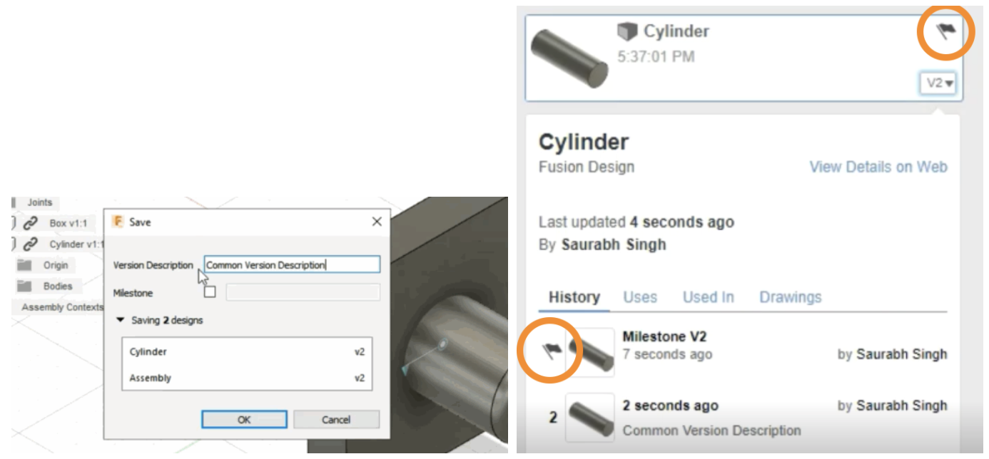
Previously in Edit-in-Place workflows, if you tried to save the changes you made to an assembly with externally referenced parts and marked the changes as a milestone, the milestone was only captured on the assembly design, and not the referenced part.
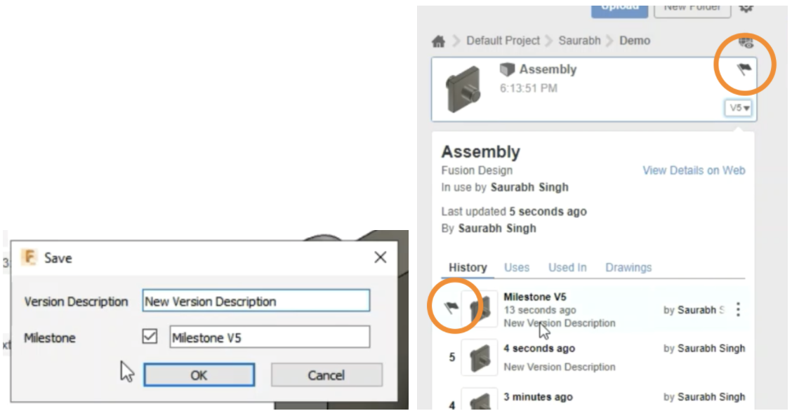
We’ve expanded the Save capability to now include more granular options for you to capture milestones, on the assembly as well as the part level.
Improved! Undo now undoes document state

When you make changes to a saved document, you’ll notice that an asterisk (*) will appear next to the document name in the document tab. This is to show that there are unsaved changes in the document. Apparently if you clicked on the Undo button, it undid the action but didn’t undo the “dirtied” document state. We fixed this behavior so that when you undo, it undoes the action as well as the document state, back to how it was before you made the change, reflecting this by removing the * from the document name in the document tab.
Improved! Changing workspaces and going into Edit-in-Place no longer dirties document
Speaking of dirtying documents, apparently going in and out of Edit-in-Place without actually doing anything added an asterisk to your document, effectively dirtying the design. Switching workspaces from Design to something else also dirtied the design. We’ve tweaked the behavior so that now when you go in and out of Edit-in-Place without any actual modeling or switch to another workspace, the design remains un-dirtied.
See help documentation for Edit In Place
Improved! Zebra, Curvature Map, & Curvature Comb Analysis usability

Previously when you used the Zebra, Curvature Map or Curvature Comp Analysis on your designs, discoverability of various options was not obvious. Placement of the sliders was also sub-optimal, so we decided to improve it. Now the options in these analysis types appear as buttons, no longer hidden under drop-down menus. Clumsy incremental step arrows are gone, and placement of the sliders are also in-line with their respective options, making the overall usability of the dialogs much more intuitive.
See help documentation for design analysis toolsNotable Fixes
Sketching & Modeling
New! Sketch Text along path
Design Workspace > Create Sketch > Text > Text on Path Type
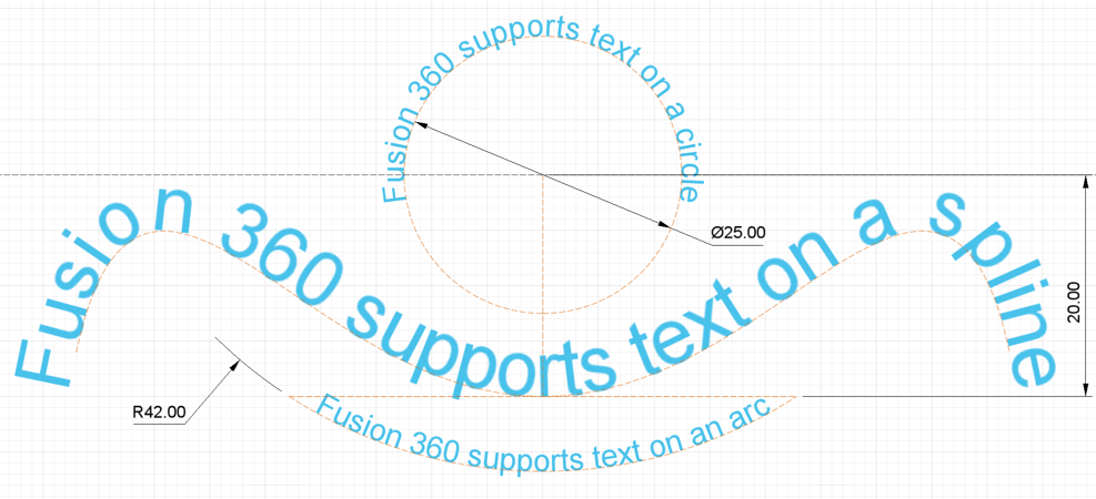
We are excited to announce improvements to Fusion 360 sketch text. The team has been under the hood working hard on improving general text capabilities with the aim to provide a more modern text experience and lay the foundation for improvements as we move forward.
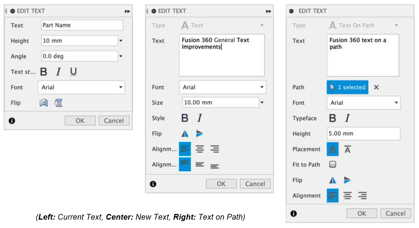
As you can see from the screenshot, the options in the command are all self-explanatory. Check out Kevin Kennedy’s fresh new tutorial and see the command in action. Give it a try, show off what you’ve done with it, and let us know what you think!
See help documentation for Sketch > Text
New! Arrange* and Simplify tools can be accessed from the Design workspace
Preferences > General > Design > Enable Arrange and Simplify tools
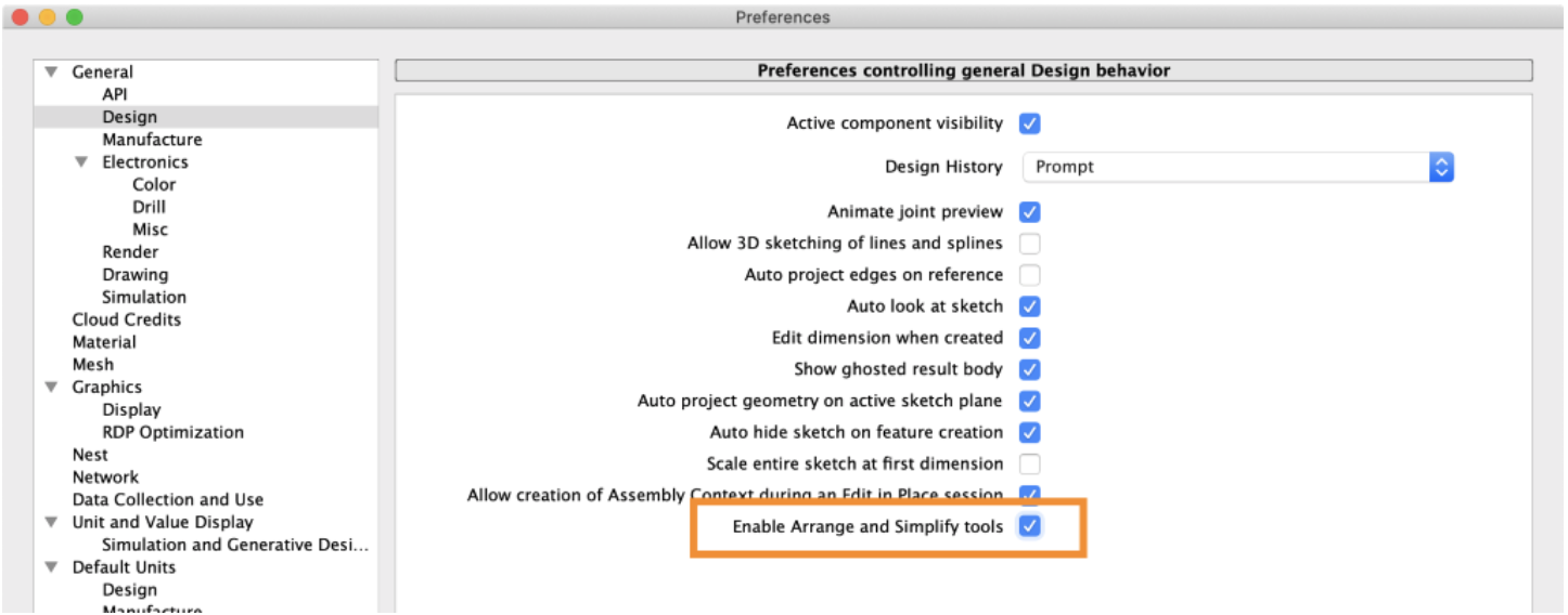
You now have the option to turn on Arrange and Simplify tools in the Design workspace by going to the General > Design section of your preferences and checking the “Enable Arrange and Simplify tools” box. Once applied, you’ll see the Arrange and Simplify tools under the Solid Tab > Modify panel drop-down menu.
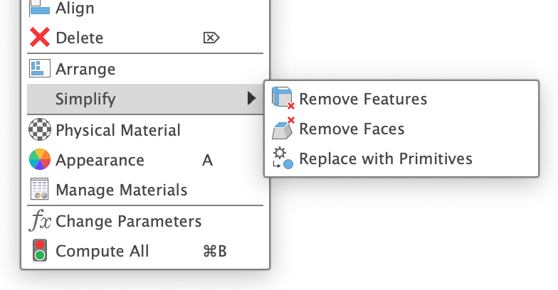
See help documentation for Simplify
* Not seeing the Arrange tool? Here’s why.
Improved! Tangency Weight for Fillet Command
Design Workspace > Solid Tab > Modify Panel > Fillet
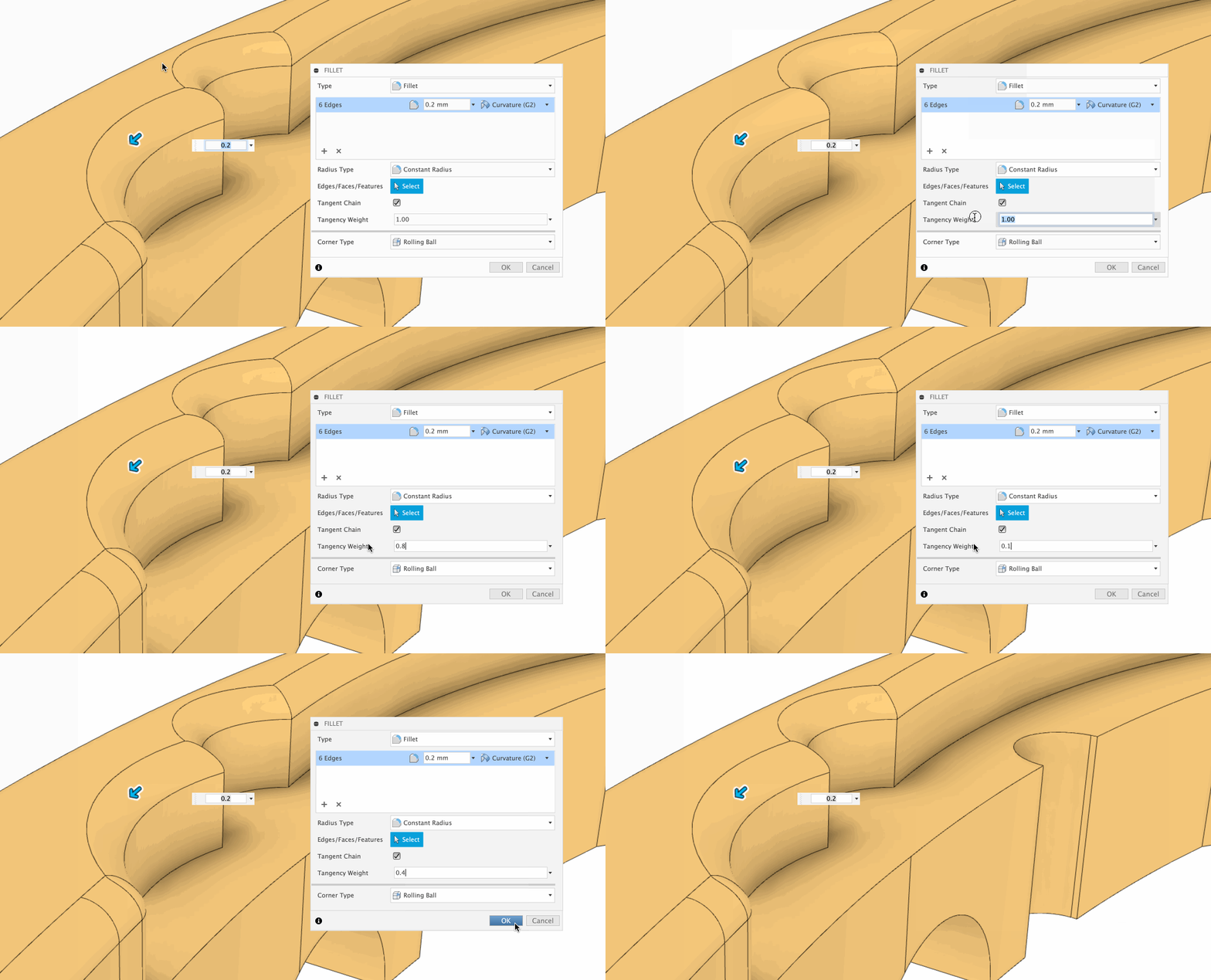
We’ve added a new option in the Fillet command called Tangency Weight. Changing the value of the Tangency Weight will alter the tangency curvature of your fillet, allowing you to fine-tune the geometry of your fillet.
See help documentation for Fillet
Improved! Create Ruled Surfaces from sketches
Design Workspace > Surface Tab > Create > Ruled
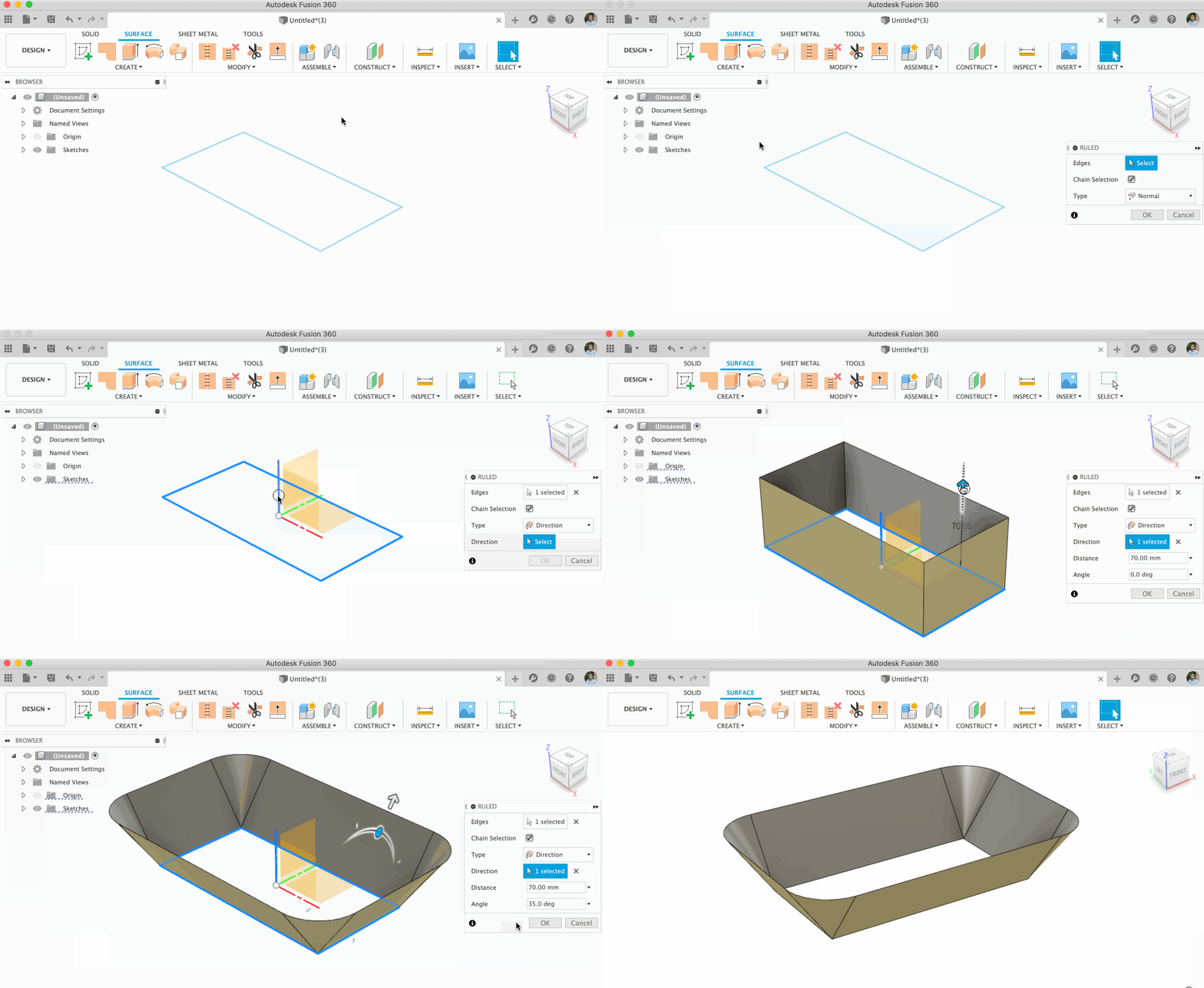
Over this past summer, we introduced the Ruled Surface tool in the Surface tab. Since then, we’ve tweaked our dedicated algorithms to be more robust, which improved the performance of creating ruled surfaces from a sketch.
Notable Fixes
Electronics
New! Additional control of hole placement with reference
File >New Electronic Design > PCB Editor > 3DPCB
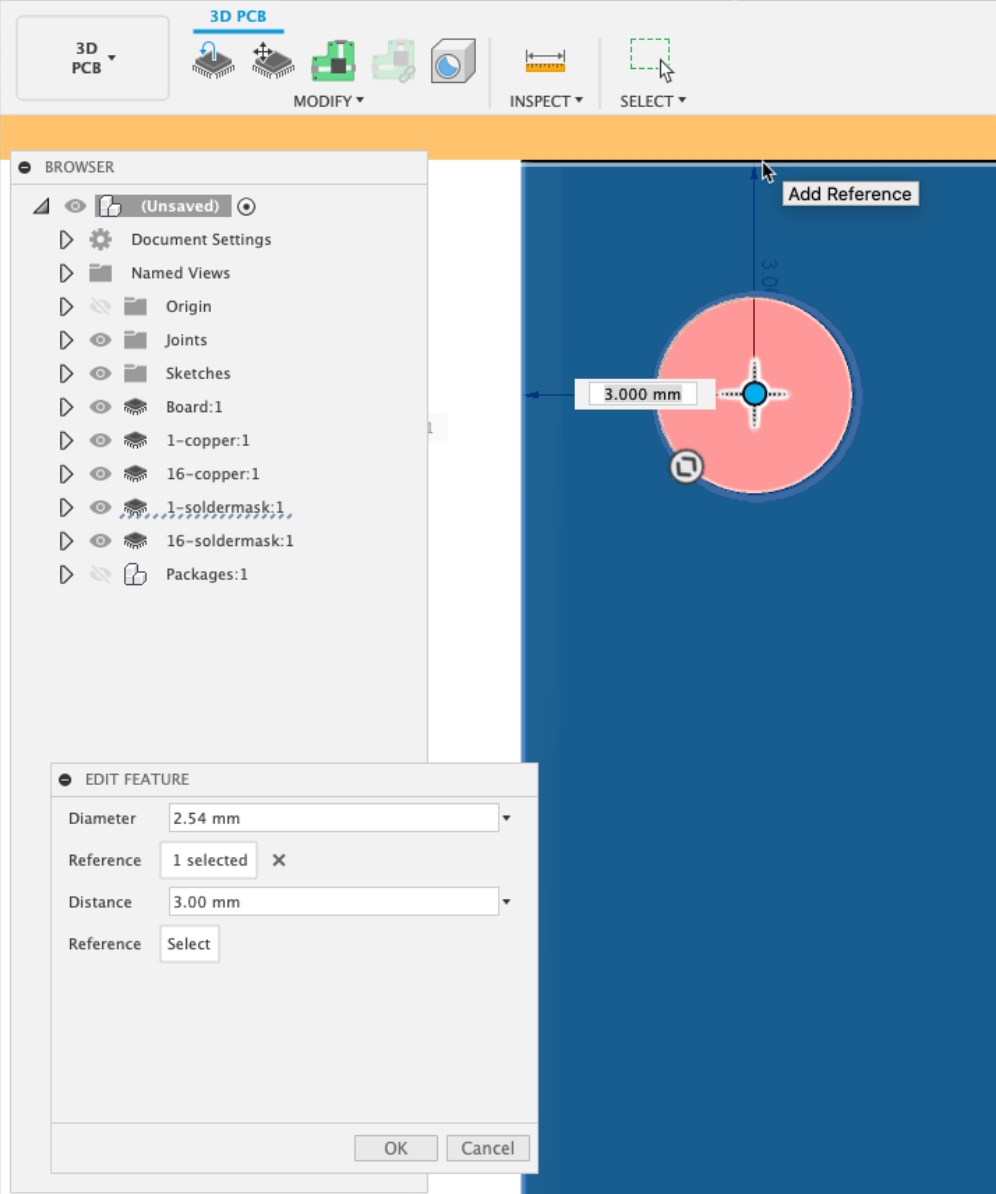
Now you’ll be able to place holes directly on the 3DPCB editor using references. Holes placed directly on the PCB will also appear on the 3DPCB timeline, allowing you to fine tune their location by parametrically referencing other asset edges.
New! Customizing Footprint Pads
File > New Electronics Library > Create New Package
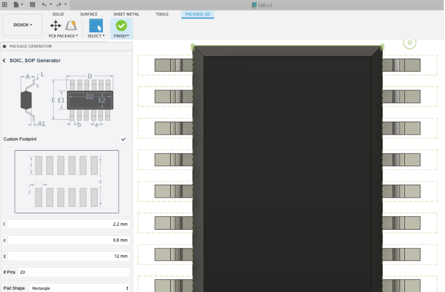
Fusion 360 library editor includes a comprehensive package calculator which will build a 3D model and component footprint in a single step. In the Package Generator UI dialogue, you now have the option to choose to use the IPC compliance or customize footprint parameter without compromising the 3D model details. There are some benefits to changing pad size such as making the pad larger for hand soldering or smaller due to space constraints. This feature is currently being supported in the SOIC, Chip, SOD and Molded Body templates, more will be added in future updates.
New! Support for True Type Fonts
File > Electronic Editor > PCB Editor
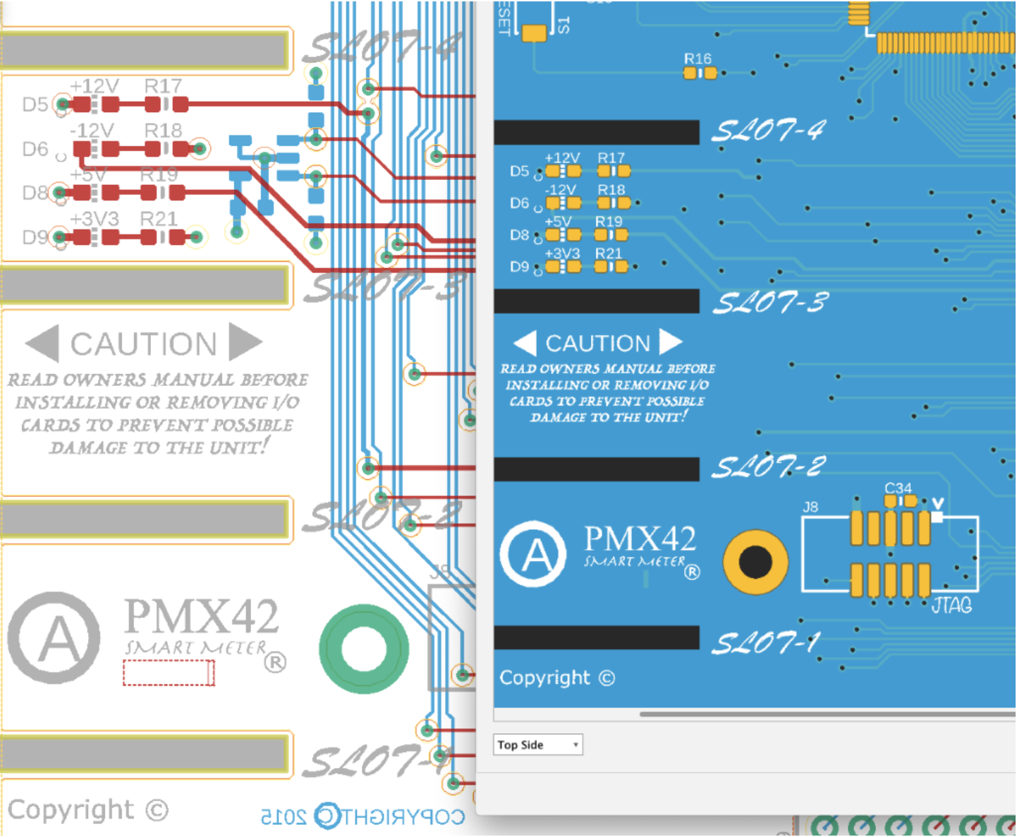
In our last update, we added manufacturing export support for the native fonts available in Fusion 360 electronics editors. Many of you have asked for font support, which was only accessible by importing a Bitmap file. We now support all installed True Type fonts; you’ll able to document your schematic and circuit board with different fonts that will genuinely enhance your electronic designs’ aesthetics, and all true type fonts are fully supported in CAM Gerber Output.
New! Create design copy
File > New Electronic Editor > Schematic Editor
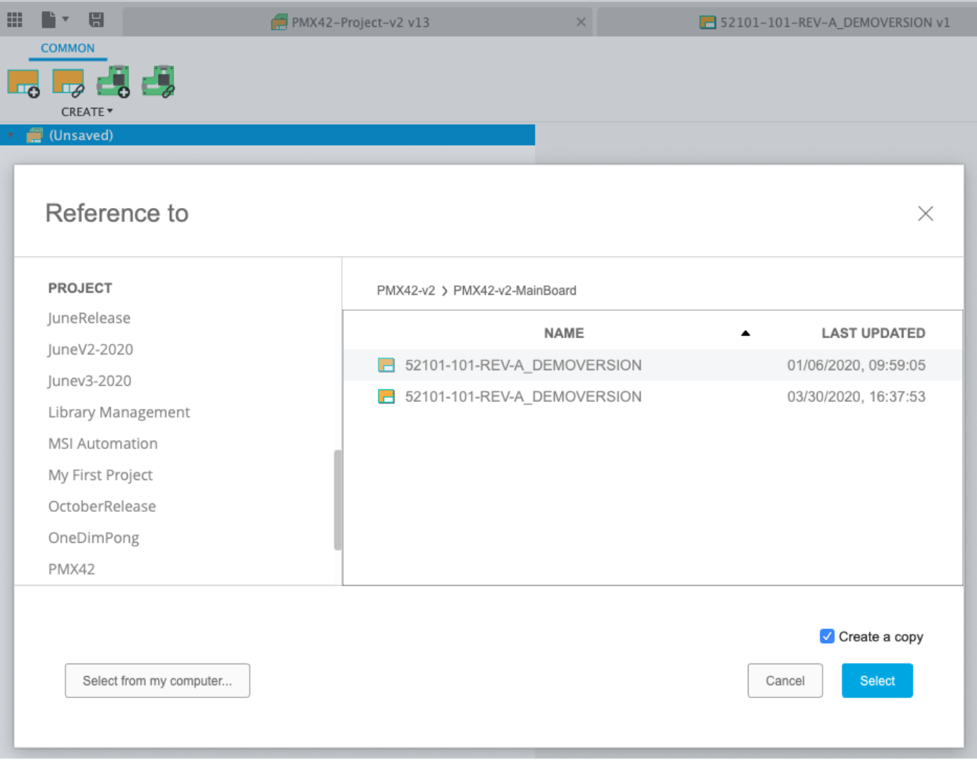
After creating an electronic document, you have the option to either create a new schematic or board or reference existing ones. It’s common to re-purpose existing designs and adapt them to a product update. Referencing existing designs to a new design may cause consistency issues to the original design if new components or connections are added. The option to “Create a Copy: has been added to the ‘Reference to’ dialog box which will protect the integrity of the original design.
Improved! Spice Model Assignment
File > New Library Editor > Device Editor
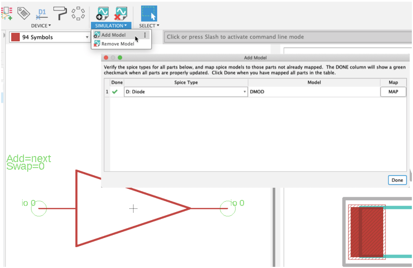
Fusion 360 schematic editor does include a NGSPICE engine which allows you to run Analog, Digital and Mix Mode simulation on your schematic. You’ll need to add a SPICE model to your component for this to work. We’ve updated the interface to easily find the tools to add and remove SPICE models to your schematic symbols. Mapping of SPICE models can be performed in the library editor or directly in the schematic.
Improved! Validation input notice
File > New Electronics Library > Package
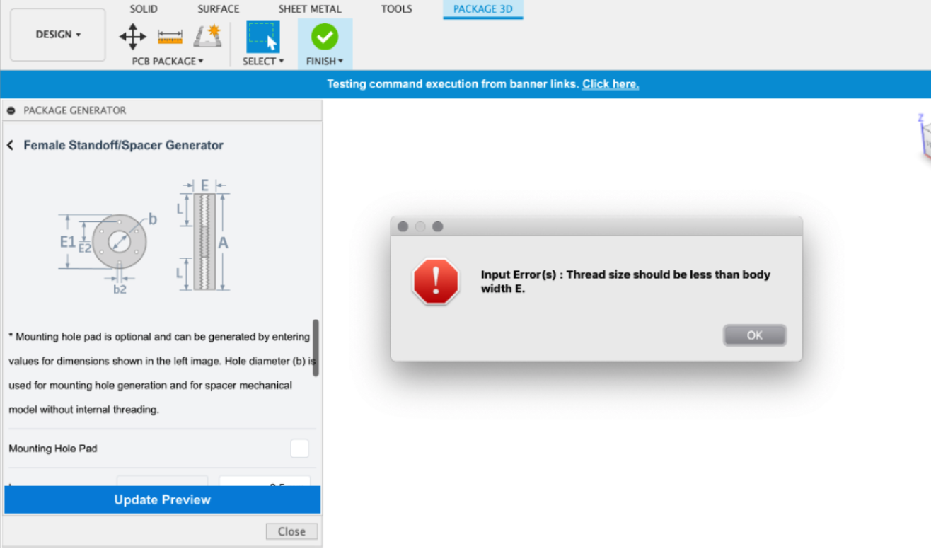
We added a validation error message to package generator templates so that it shows detailed messaging regarding the offending parameter.
Improved! Device UI
File > New Electronics Library > Device Editor

The new device interface provides you more details regarding the device footprint, package name, variant name and if a 3D model has been successfully assigned.
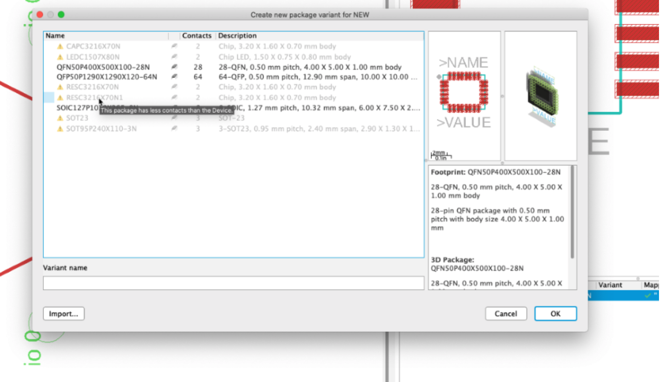
The device UI has been updated to provide more detail of which footprints can be used.
Notable Fixes
Generative Design
New! Favorite outcome iterations
Generative Design Workspace > Explore
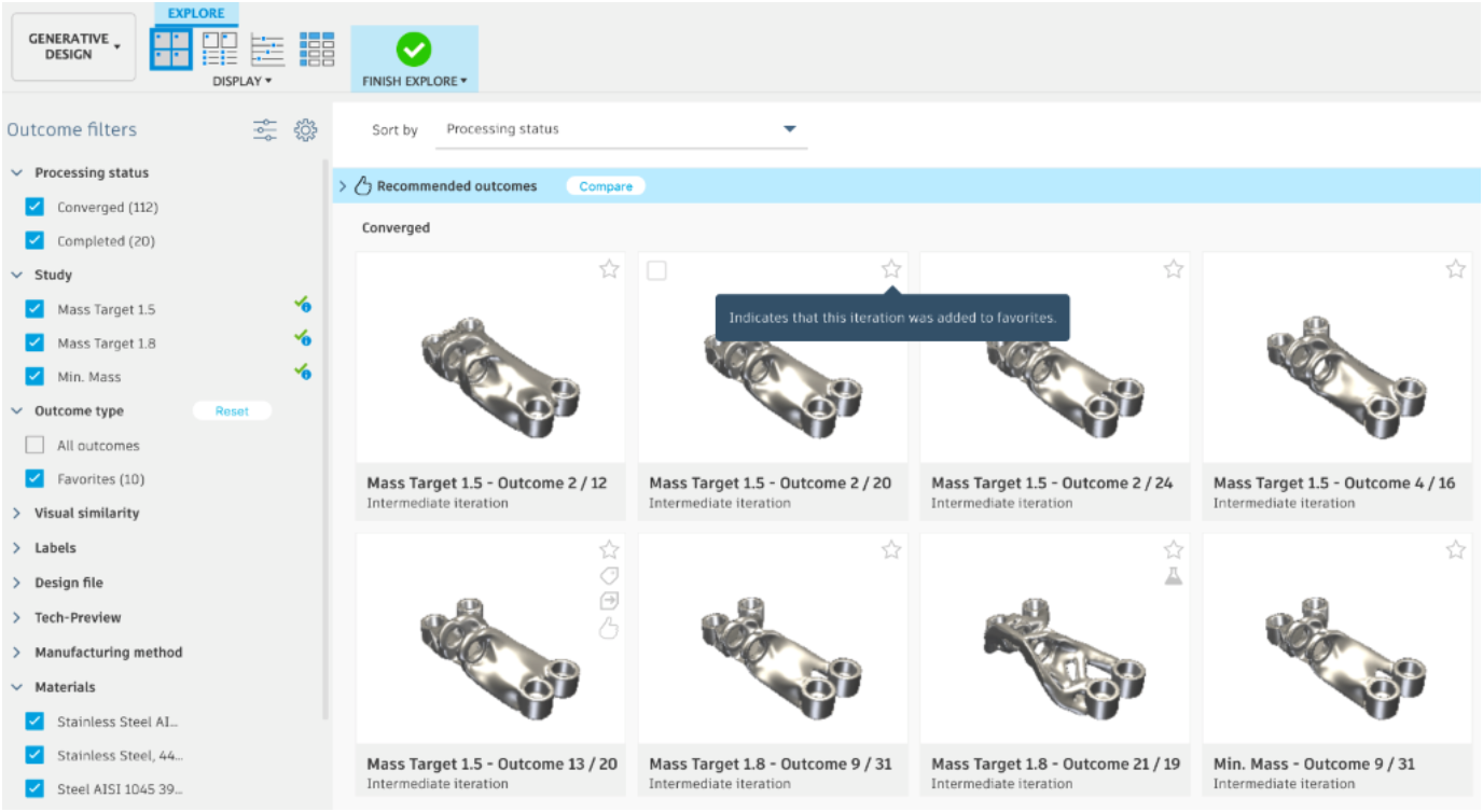
You can now add Intermediate outcome iterations to Favorites and treat them as regular outcomes. Once added, favorite outcome iterations are displayed in the Explore views and can be filtered by dedicated filter. Favorites option enables you to compare the intermediate iteration with other outcomes. In addition, it gives you the possibility to analyze different iterations from the same outcome.
See help documentation for Favorites
New! Iteration trend
Generative Design Workspace > Explore
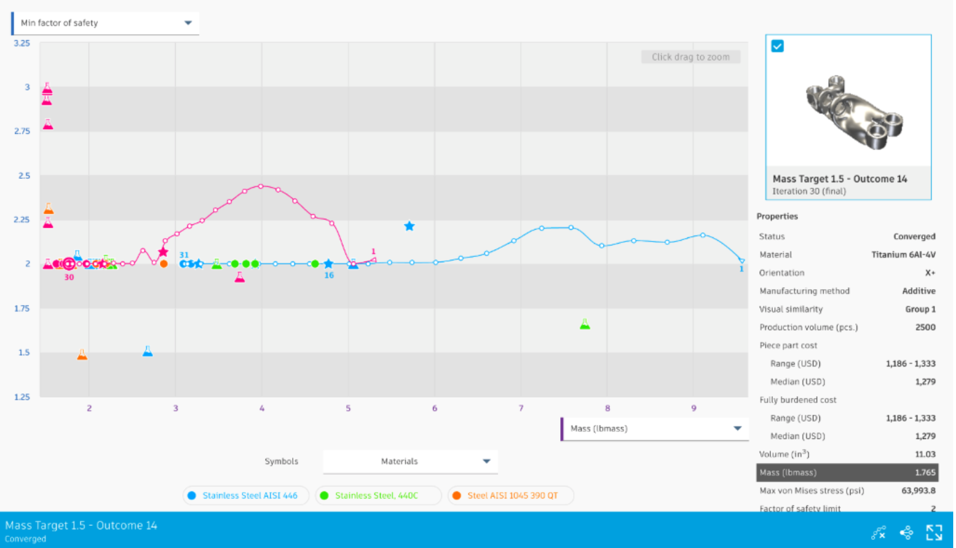
We’ve also expanded on the Scatter Plot View functionality to show Iteration trend of the optimization process of an outcome.
See help documentation for Iteration trend
New! Recommended outcomes
Generative Design Workspace > Explore
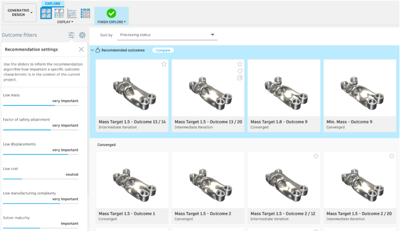
The recommendation engine suggests recommended outcomes based on the specified criteria and displays the top 4 outcomes in Recommended outcomes pane to help you quickly find the outcomes that most satisfy requirements among all generated results. Recommendation settings pane also allows you to customize the criteria and determine how important they are.
See help documentation for Recommended outcomes
Improved! Iteration bar usability
Generative Design Workspace > Explore
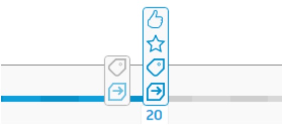
From now on all main characteristics of an outcome iteration such as: created design, labels, favorite and recommendation will be presented as a separate badge on the iteration bar in the Outcome View.
Improved! Additional outcome for 2 axis cutting, 3 axis milling, and 5 axis milling manufacturing methods
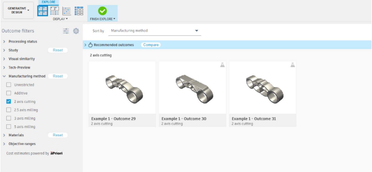
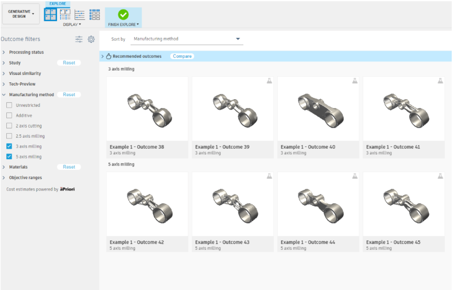
Experimental Generative Solvers and Features Tech Preview provide two additional outcomes for 2 axis cutting manufacturing setups, as well as for each 3 and 5 axis milling manufacturing setup. Symmetry constraint is supported for 3 and 5 axis milling manufacturing.
Simulation
New! Remote Constraints
Simulation Study > Structural Constraints > Remote
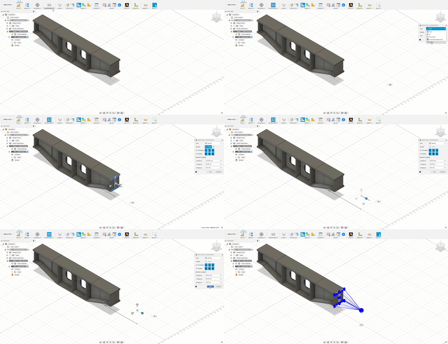
You can now add a Remote Constraint as part of your setup definition for your Simulation Study. Pick the model face and then define the node location using x, y, z co-ordinates and fix the translational and rotational directions. The Remote Constraint boundary condition is transmitted through the line elements to the model.
New! Remote Moment
Simulation Study > Structural Loads > Remote Moment
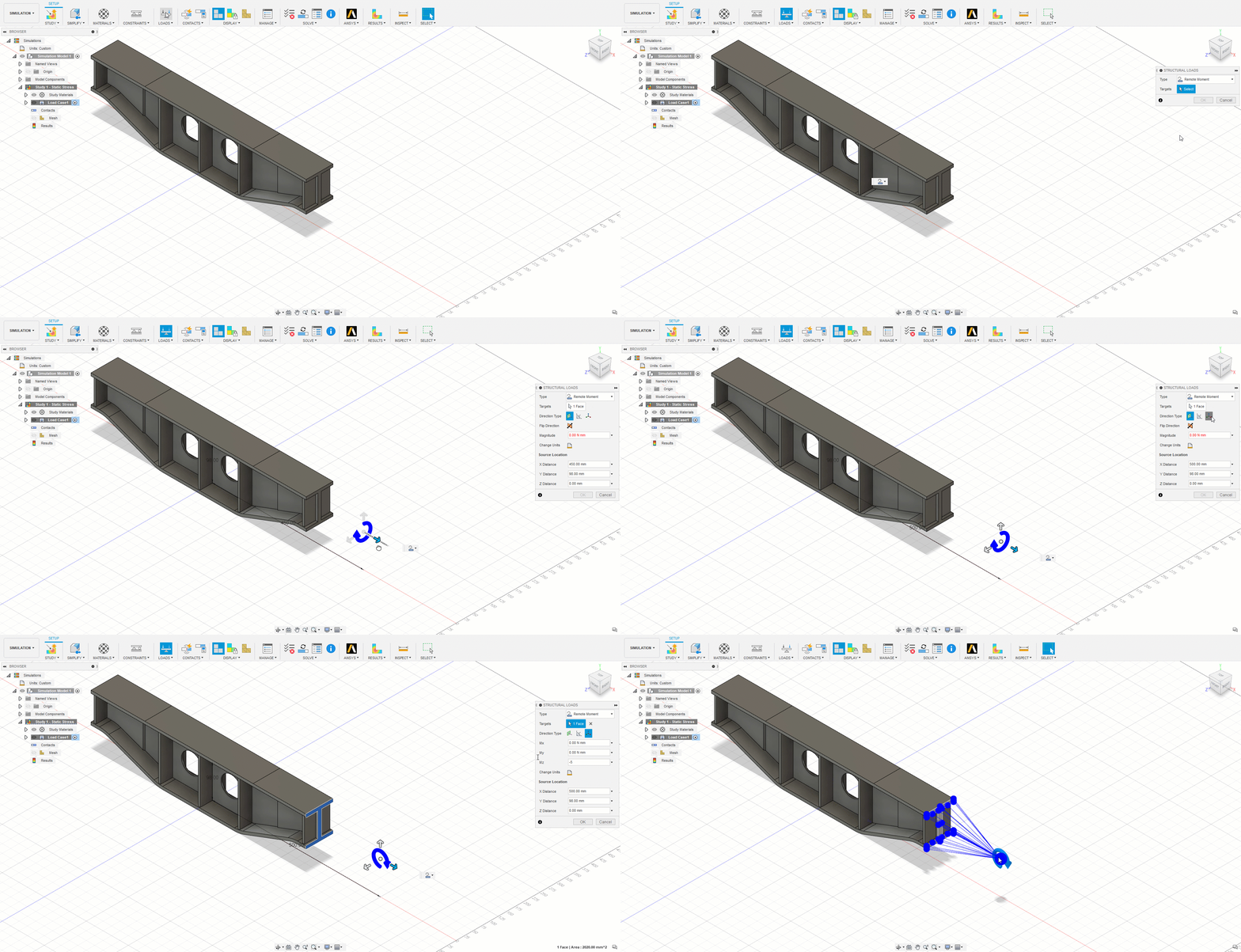
In addition, you can also add Remote Moment. Pick the model face and then define the node location using x, y, z co-ordinates and then provide the moment value either normal direction or angle direction with reference or x, y, z vectors. The Remote Moment boundary condition is transmitted through the line elements to the model.
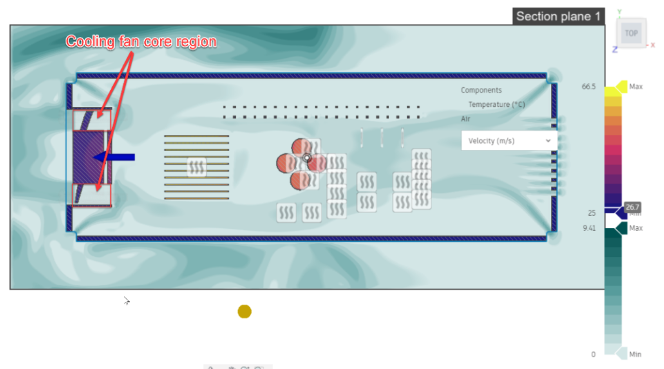
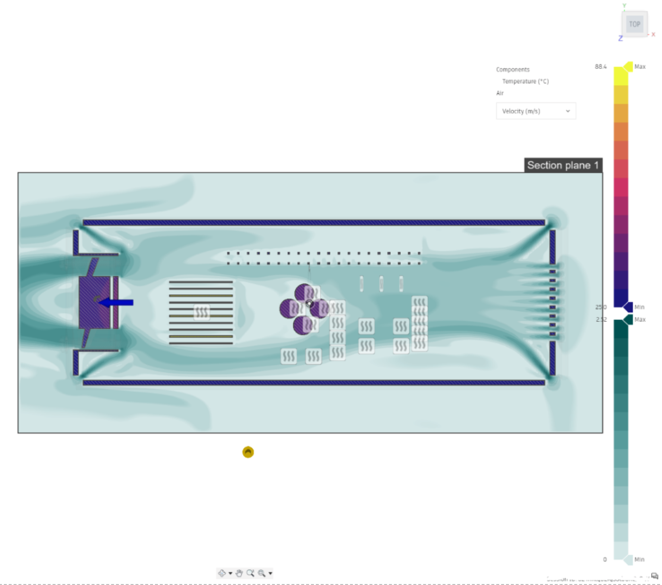
Improved! Velocity Field shown in fan core region
Previously (as shown below), the cooling fan blade or core region showed zero velocity when looking at results. This could lead to confusion on how the air was being moved by the fan.
Now the velocity is shown in the fan core region for all results viewing.
Drawing
New! Create a ‘Hierarchical’ or ‘All-Level’ Parts List
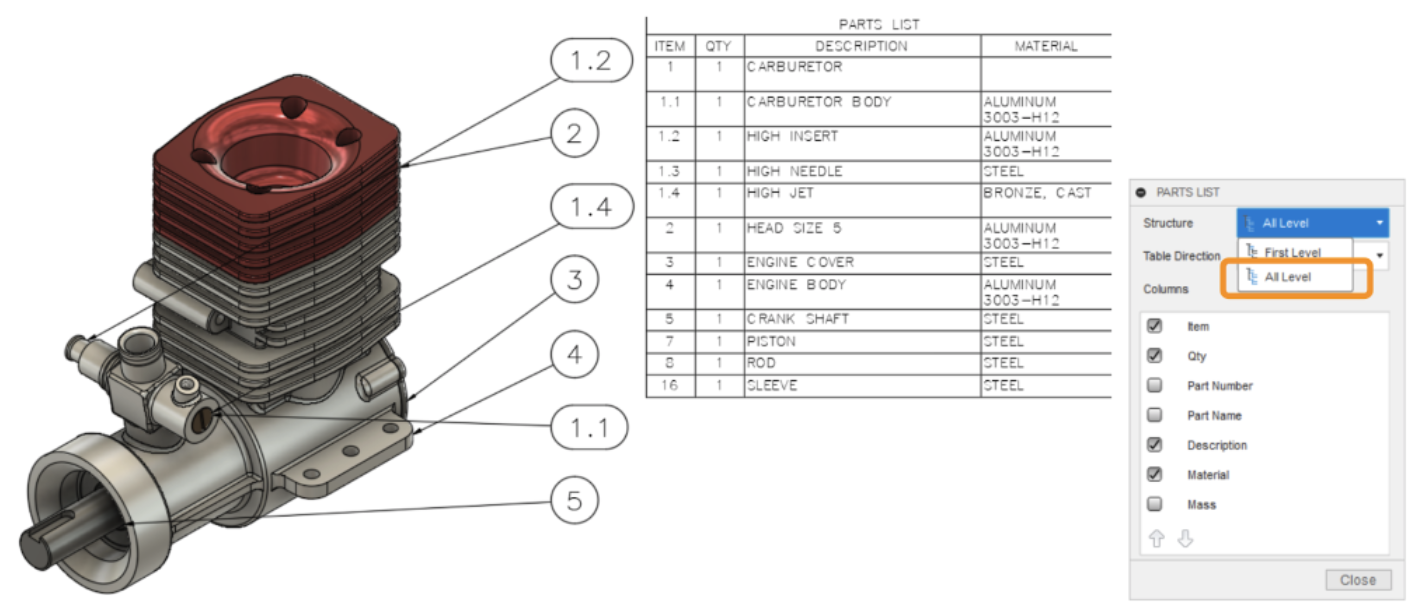
Up until now in the Drawings environment, your parts lists were restricted to top level components only, preventing you from diving into your subassembly structures. With this update, the Parts List command lets you choose between a ‘First’ or ‘All Level’ structure, with All Level parts lists listing all sub-assemblies and sub-components, with support for auto-ballooning, renumbering at the first or last ‘level’, and templates.
New! Hole and Thread Notes
Drawings > Text > Hole and Thread Note and Note
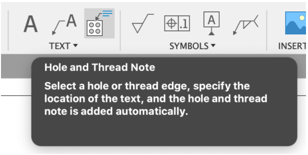
One of the most widely requested features has landed with this release! We’re happy to inform you that you now have the option to create Hole callouts with the new Hole and Thread Note command.
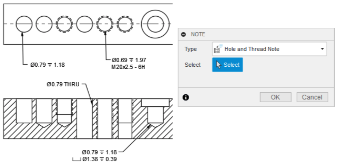
You can now automatically place hole notes for hole features belonging to a selected edge in accordance with ISO and ASME standards (depending on your drawing). While we don’t support Thread features quite yet, we plan to get there soon (thus the name 😉). There’s more to this feature than meets the eye – read more about the smart Note command here to fast–track your annotation placements, hole notes included.
See the drawings roadmap update
Manufacture
New! Manufacturing Models
Manufacture workspace > Setup tab > Create Manufacturing Model
Ever wanted to make manufacturing-specific model edits, without altering your original design? Manufacturing Models can help you do that.
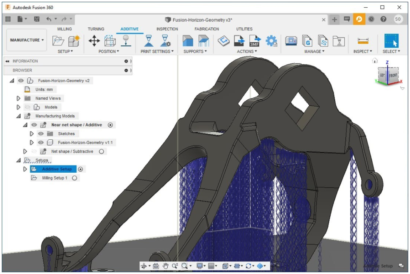
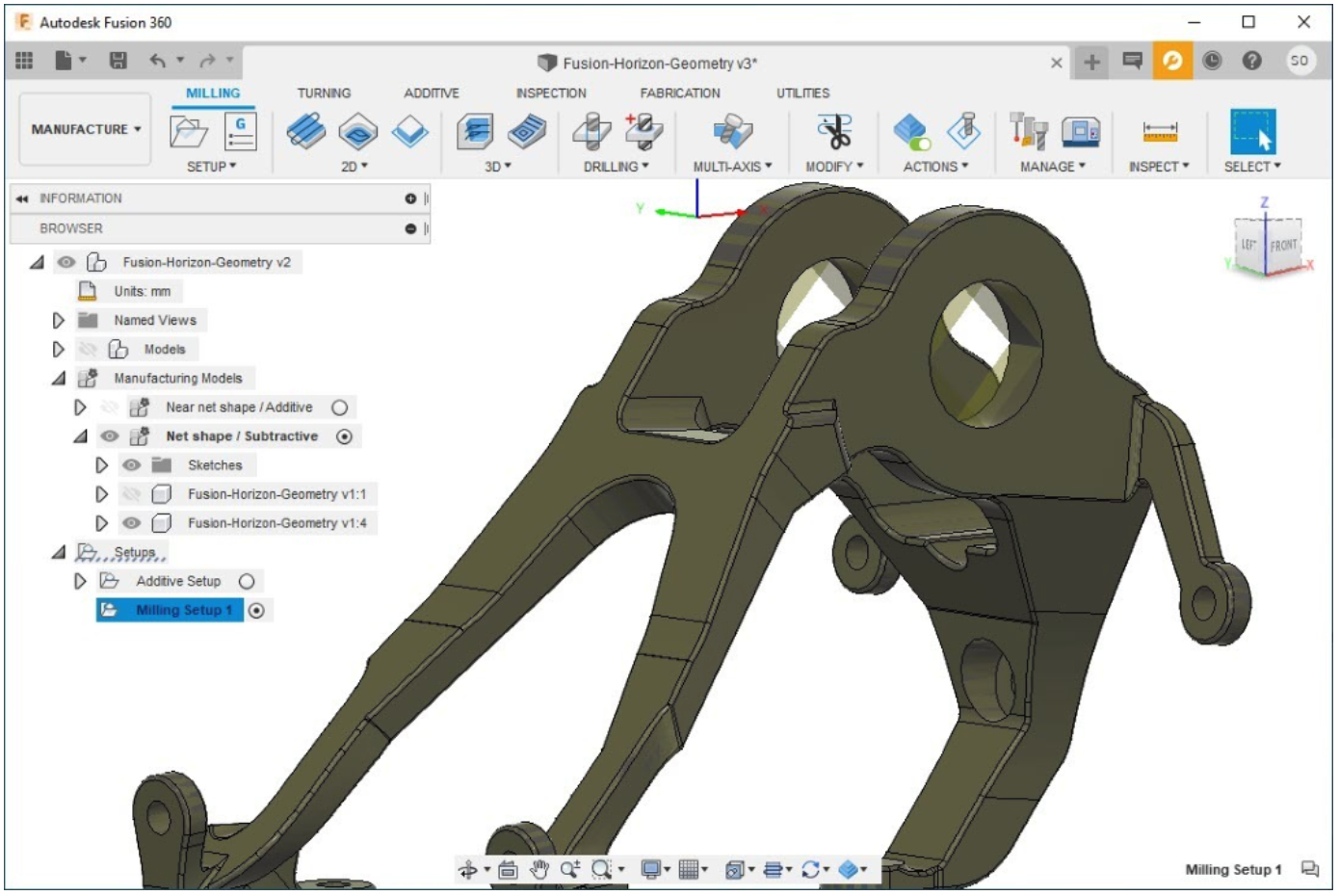
You can now create multiple Manufacturing Models in the Manufacture workspace that reference models from current document or even from external documents. You can also edit these Manufacturing Models to simplify your manufacturing operations and doing so won’t affect the original Model. However, if at any point you go back to the Design workspace and make changes to the original Model, then those changes transfer across to all existing and future Manufacturing Models.
One common example (shown above) could be creating near net shapes (NNS) for Additive and Subtractive workflows without altering the original Model.
See help documentation for Manufacturing Models – How-to?
Example 1: How to add a fixture and patch surface
Example 2: How to model stock and use de-featuring tools
New! Grooving Tools in Profiling
Manufacture > Turning > Profile Finishing
One of the big advantages of concentrating our efforts on the turning algorithm was that it set us up for a more flexible environment. Part of the long-term plan is to allow users the ability to use any tool type in any type of strategy.
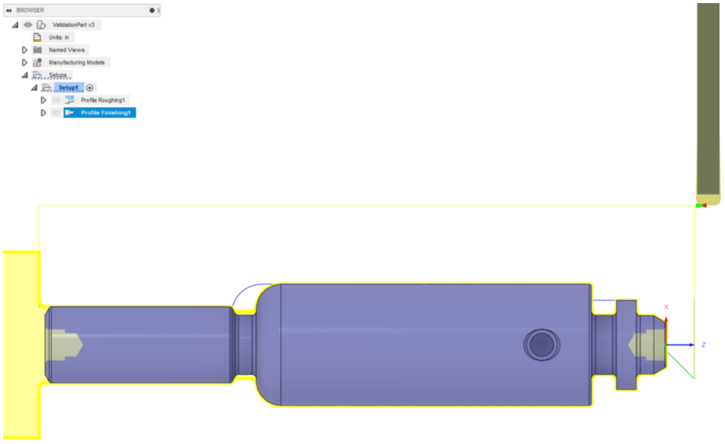
Allowing Grooving tools in Profiling strategies is the first step in that direction, starting with Profile Finishing and soon after we hope to roll out the same ability into Profile Roughing. This puts the more control into you, the users, to use these strategies without limitations.
New! Template Library
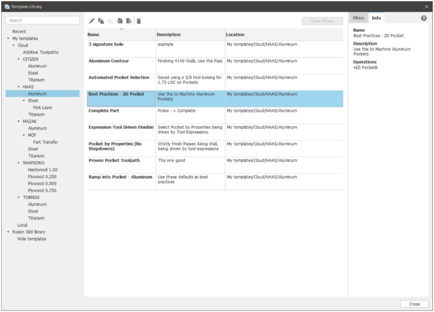
The new template library is a powerful way to store, manage, and re-use toolpath templates in Manufacturing. They are the best way for you to automate your programming. We have a fresh more blog post diving deeper into how this all works in Fusion 360, so check it out to learn more.
Learn more about the Manufacturing Templates and the New Template Library
New! Part Alignment (Extension Feature)
Inspection > Probing > Part Alignment
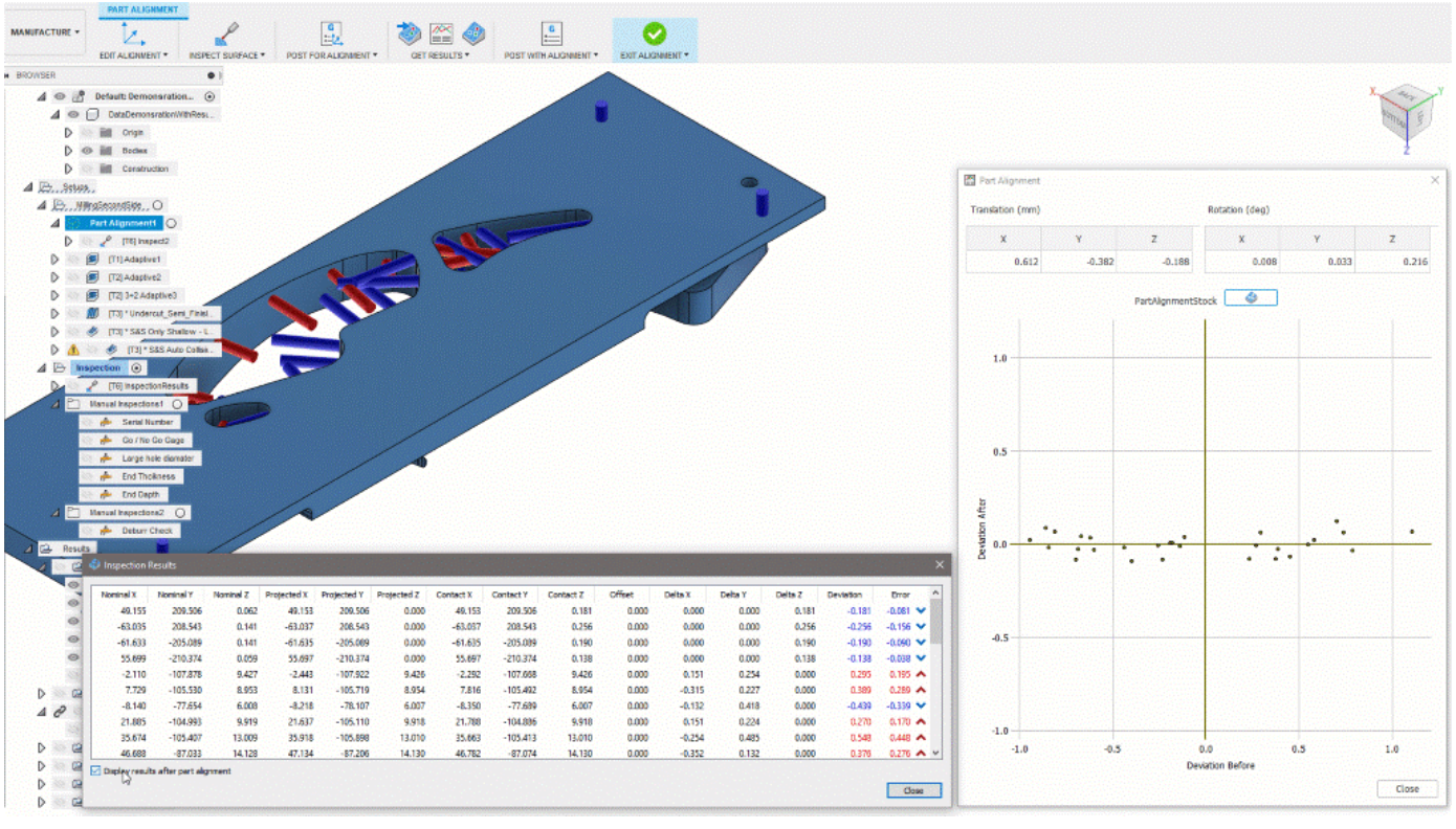
Part setting probing for complex workpieces on a milling machine. Measures the stock condition of free-form geometry using ‘Inspect Surface’ probing and adjusts the position of the milling toolpaths to optimize the distribution of available stock. Typical applications are machining setups for complex shaped workpieces created by near net processes such as casting or forging. Part Alignment allows optimization for a 3, 4 or 5 axis setup depending on the capabilities of the machine. We have made several enhancements and usability improvements– including the “Import Inspection Results” listed below- since the preview earlier this year.
See help documentation for Part Alignment
Improved! Angled Entry
Manufacture > Turning > Profile Roughing > Linking > Angled Entry
It’s back, we implemented Angled Entry into the New Profiling strategies! This was one of the top requested features from the old Profile strategy.
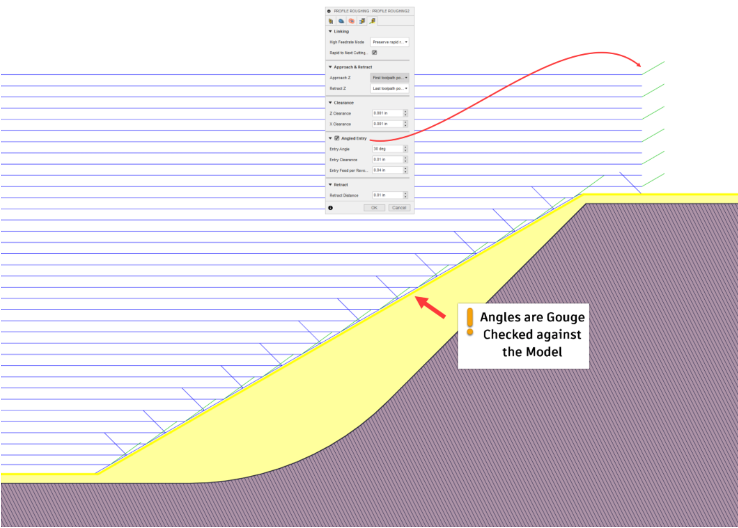
With the changes made for a more robust roughing algorithm that supports cornerstone functionality such as canned cycles in roughing strategies. learn more
Improved! Import Inspection Results
Manufacture Workspace > Inspection tab > Action Panel > Import Inspection Results
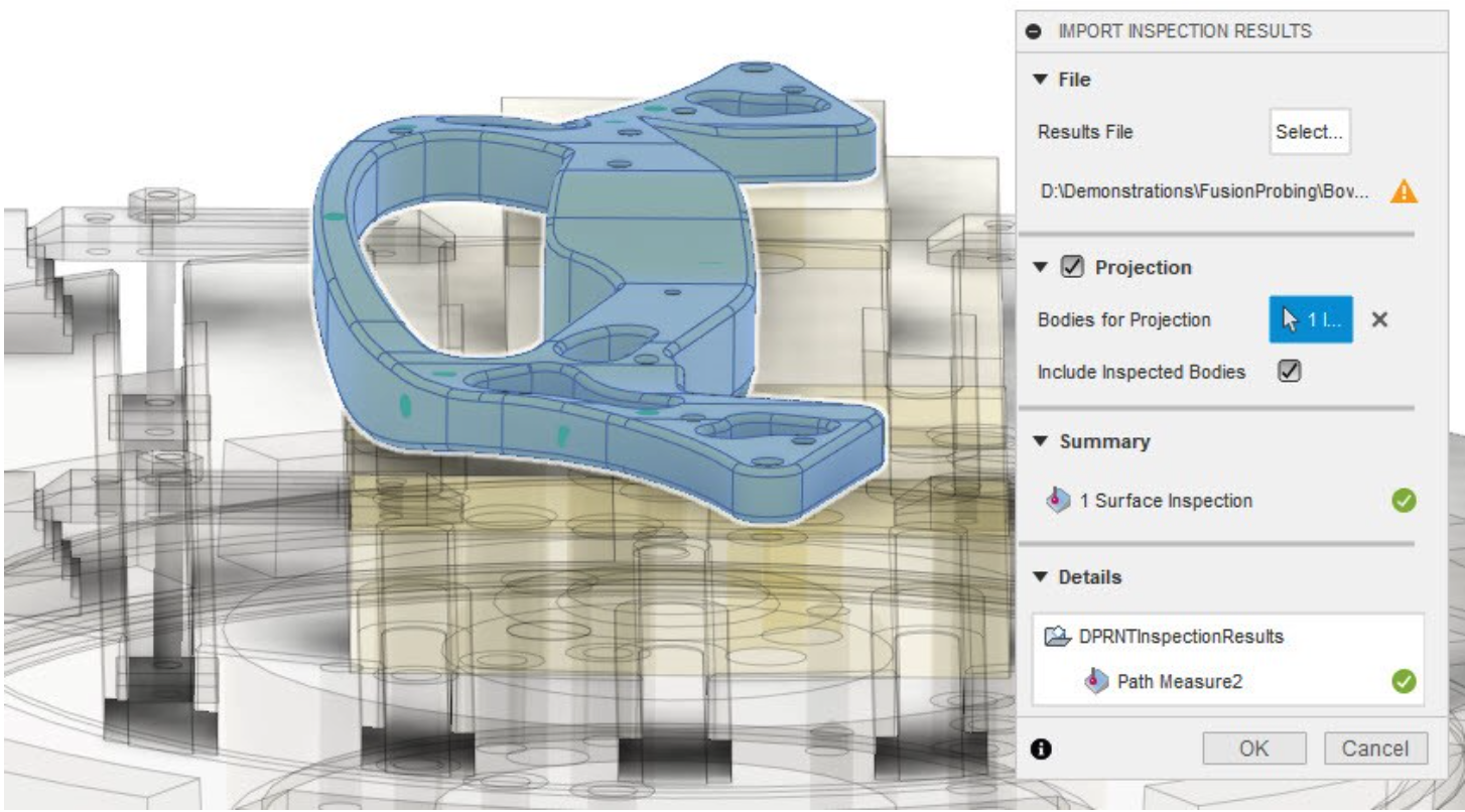
‘Import Inspection Results’ now shows a preview of the inspection results when you select the file containing the probed points or features. This helps you to visualize the results while defining the import, and allows you to set the ‘Bodies for Projection’ if necessary. Also used in the Part Alignment process, this can be very useful if you are using different bodies to model stock and fixtures.
See help documentation for importing inspection results
Improved! Inspect Surface
Inspection > Probing > Inspect Surface (Extension Feature)
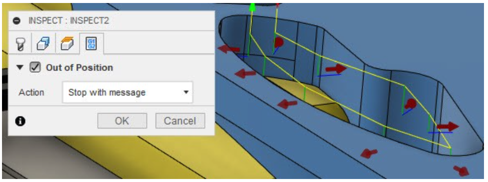
Inspect Surface has been enhanced to support real time calculation of the Inspection Results on the NC controller as the probing commands are executed. Making the Inspect Surface behavior more consistent with ‘Probe Geometry’, we have also added an ‘Action’ tab which allows you to stop the probing sequence with a message if the Inspection Results are out of tolerance.
New in Preview! Import Macro Print Results
Inspection > Action Panel > Import Inspection Results
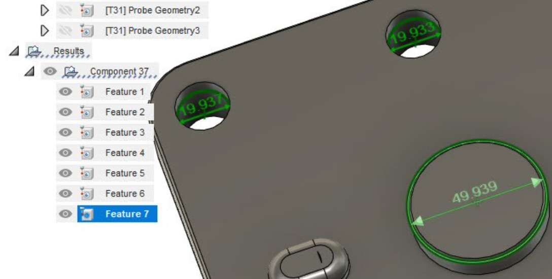
Extending the scope of the inspection reporting, this new capability allows you to include circular ‘Probe Geometry’ features in your Fusion 360 inspection report. Now available in preview, this functionality allows you to measure critical holes and bosses and record the results in Fusion 360. This capability imports print results produced by probing macros (such as Renishaw), creates a graphical visualization of the results, and allows you to include these features in an inspection report.
See help documentation for inspection results
New in Preview! Turn and Tilt Tool Orientation Controls (Extension Feature)
Milling > Toolpath Strategy Form > Geometry Tab > Tool Orientation > Turn and Tilt
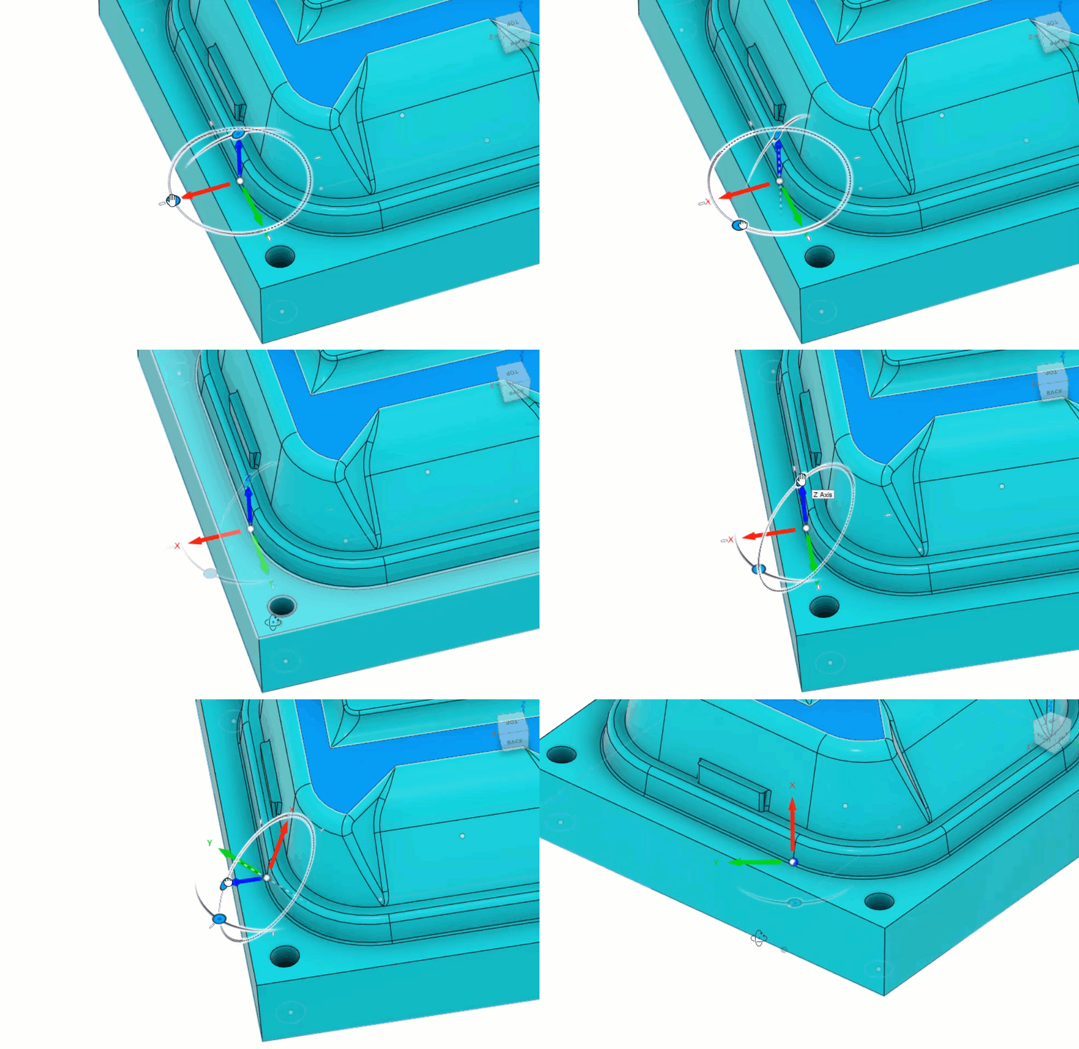
New Tool Orientation graphical controls, Turn and Tilt, have been added into the Tool Orientation section of the toolpath strategy form. These new controls enable you to adjust the Tool Orientation to the desired direction. The Turn and Tilt controls are very useful when the Tool Orientation you want cannot be defined by selecting an existing piece of geometry. learn more
See help documentation for Turn and Tilt and Align to View
Additive
New! Technology–agnostic
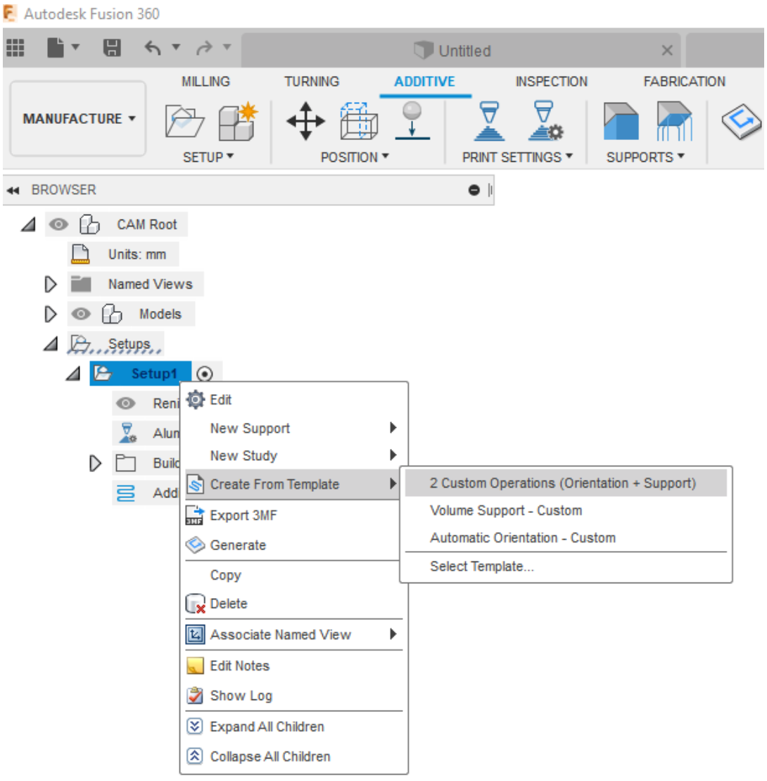
Customized Automatic orientation settings (available for FFF and SLM) and Support Structures settings (SLM only) can be stored in a template library to be reused in other Additive Manufacturing Setups which will make 3D print preparation a breeze.
New! Support for Anycubic FFF printers
Manufacture > Additive tab > Machine Library
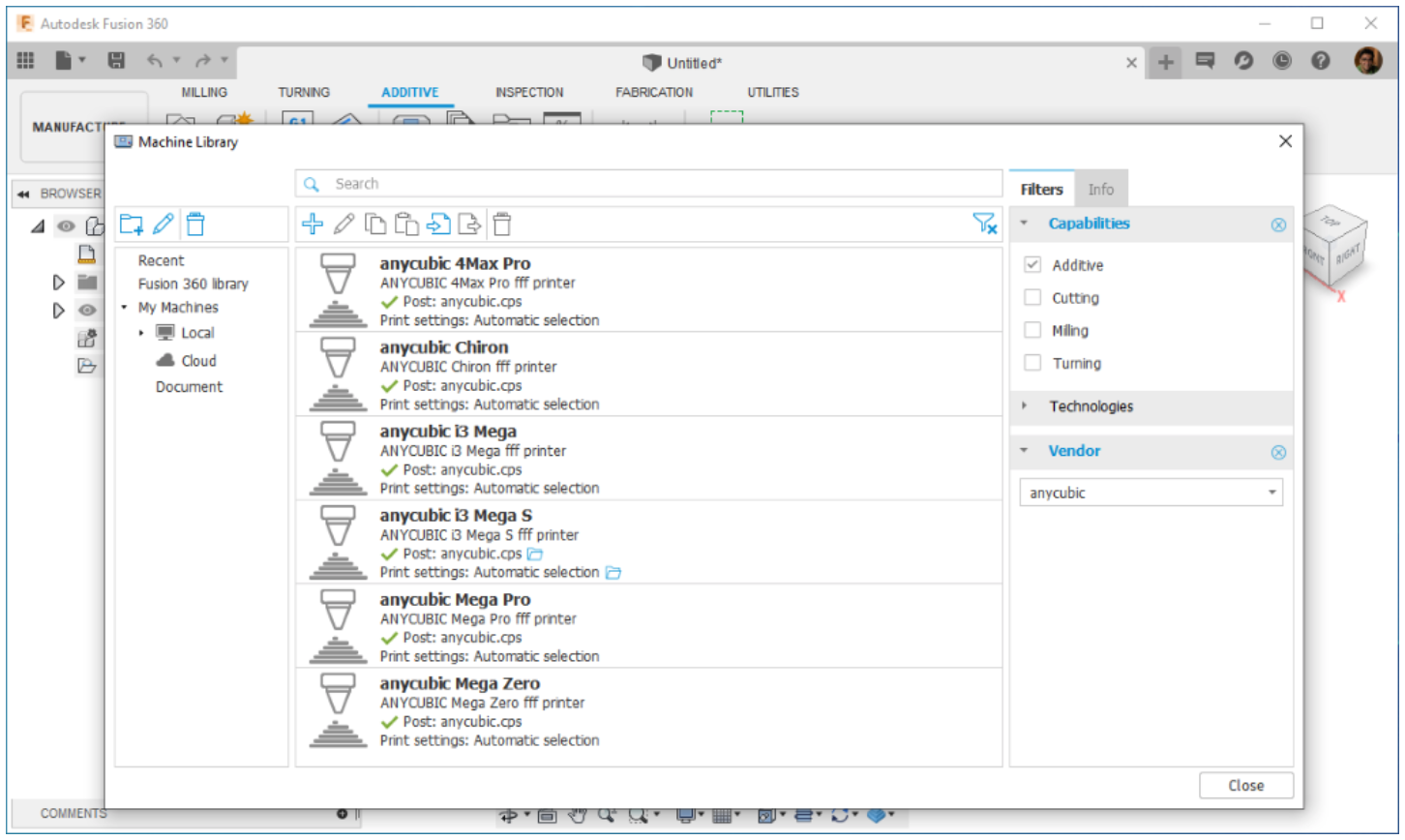
Fusion Machine library now includes six Anycubic 3Dprinters. The post library also has a post associated with these printers, so users can setup the prints and generate g-code for their Anycubic machines.
New! Additive Build Extension
Accessible from the Extensions icon in the top right corner
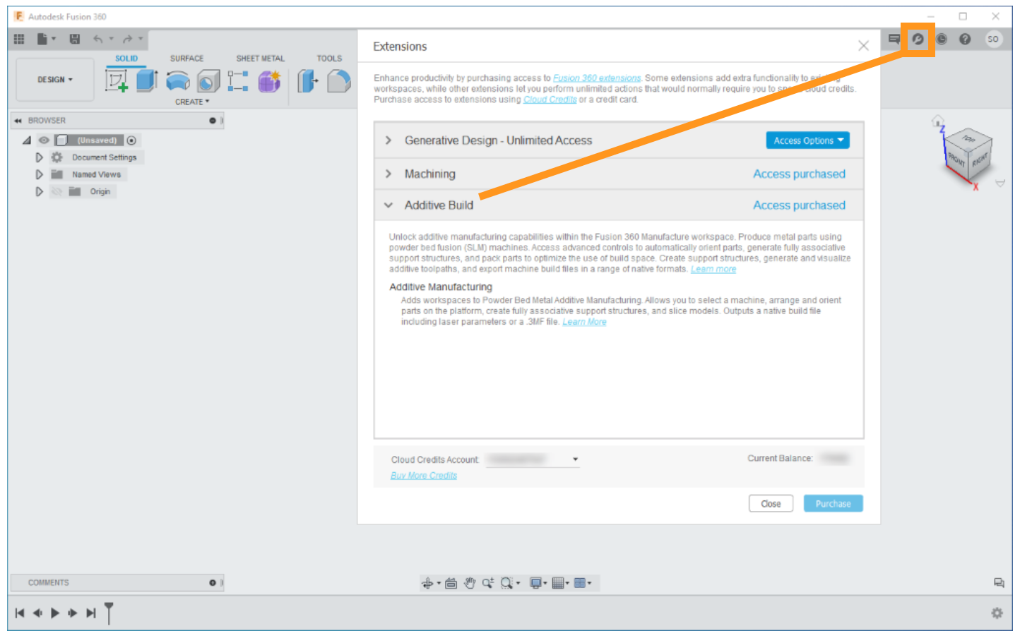
We are bringing more advanced additive manufacturing technologies into Fusion 360 by introducing Powder Bed Metal manufacturing workflows into the software, now available in the Extensions dialog under brand-new Additive Build section. This manufacturing workflow will enable you to arrange/orient parts on the platform, create fully associative support structures, slice models, and output native build files including laser parameters or a 3MF file.
Learn more about Additive Manufacturing
Improved! Multi-extruder selector
Manufacture > Additive tab > Print Setting Editor > Extruder
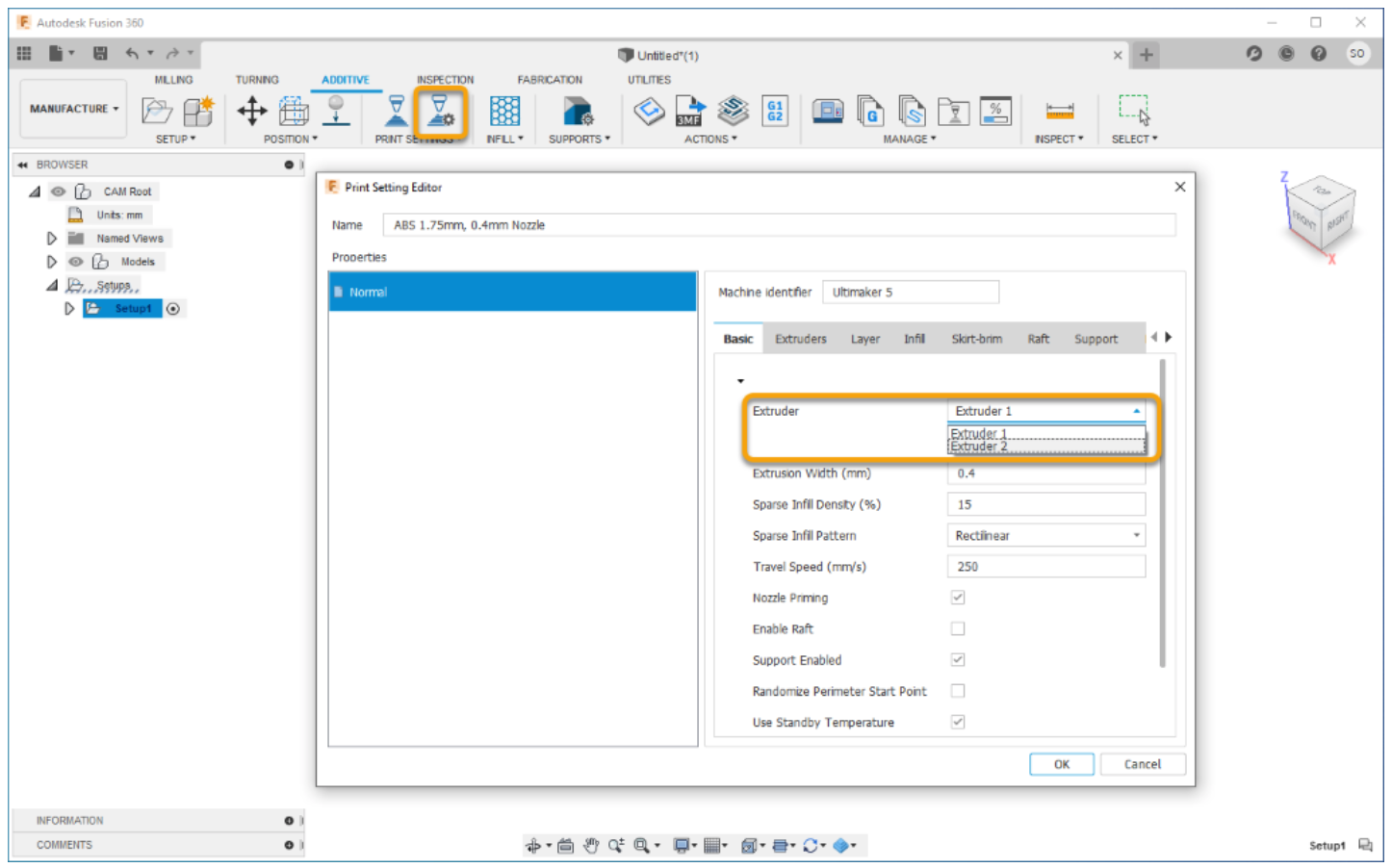
You can now choose which extruder to be used as your primary extruder for multi extruder FFF printers within the Basic tab of the Print Settings Editor dialog.
Improved! Supports panel drop-down
Manufacture > Additive tab > Supports
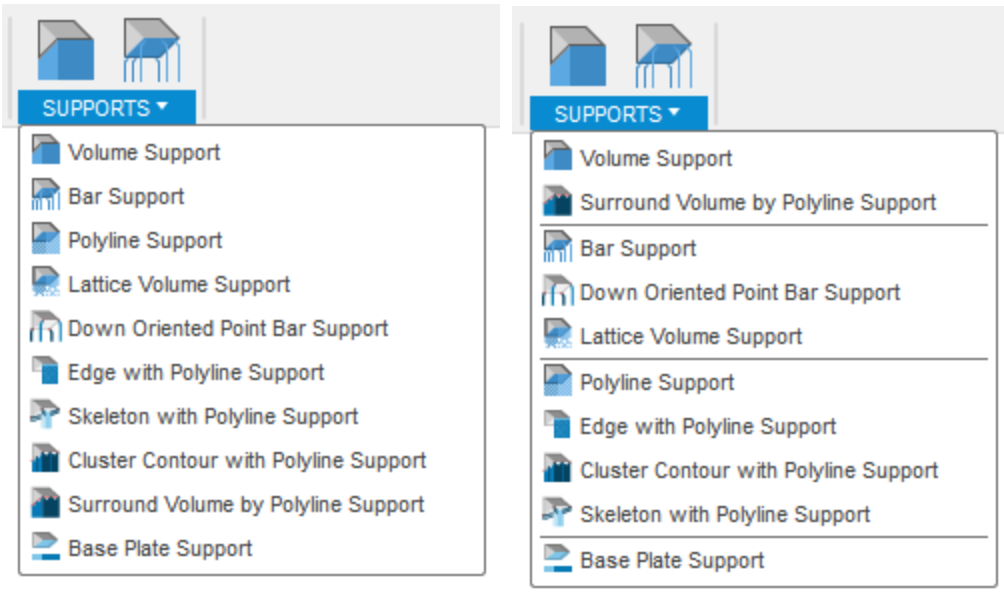
Previously, the Supports panel drop-down was a flat list of tools with no apparent order. We’ve added a few dividers and reorganized them to better suit additive manufacturing setups with metal powder bed fusion printers.
V.2.0.9011 (previous update)
Usability
Fixed: Term has Expired issue
We got reports that some of you have been getting an unexpected “Term has Expired” tag next to the Fusion 360 app name in the window frame. Apparently, some wires got crossed and triggered this incorrect tag. Sorry about that – this is now fixed.
Manufacture
Fixed: Toolpath trimming crash and selecting Hole Faces issue
We fixed an instability issue that was causing Fusion 360 to crash when you tried to edit a trimmed toolpath. This should also fix the issue around selecting Hole Faces in the Drill Operation.
Fixed: Long comment in GCode issue
xbeerd found a long string of comments in the GCode he exported from the Manufacture workspace and consequently, it was not compatible with his CNC router. We found this string and split it into 2 sections. It should work fine now.
Fixed: G1 F0 drilling issue
michalzywczak reported that he was incorrectly getting a G1 F0 (feed rate of zero) at the beginning of drilling cycles. This would cause some machines to alarm out, or just sit there endlessly, which is not good. We got this sorted and now it shouldn’t give you a G1 F0 anymore.