Learn how construction lines can help streamline your electromechanical workflows by offering precise component alignment and synchronization between mechanical and electronic designs.

Autodesk has transferred the heartbeat of EAGLE into Autodesk Fusion. We’ve successfully enabled electronics design capabilities to work, strapped some serious jet boosters, and blasted your PCB design capabilities into a new dimension of consumer product design. Let me tell you about some of the most valuable features implemented to make you want to join the thousands of users who create their electronic designs using the Autodesk Fusion for electronics.
Electromechanical design workflows: construction lines
While working on your next innovation, maintaining a harmonious design workflow between the mechanical and electronics engineers is crucial. Fusion is a great solution for this as it eliminates silos and broken workflows. It also introduces an innovative and convenient single-platform approach. Projecting an enclosure for the PCB shape only takes a few clicks to get it on the Fusion PCB workspace without needing conversion.
However, we didnt stop there as there is so much more than the board shape that needs sharing. Imagine a workflow allowing the mechanical designer to include guidelines with the PCB outline to help the electronic engineer align component placement.
In Fusion, construction lines allow you to extend that precision into your PCB design. When placing components on a board, you can reference the construction lines to maintain critical alignments and positions relative to the enclosure or other mechanical features. This ensures that your electronic and mechanical designs are always in sync, avoiding costly revisions.
Getting started
Let’s start with an enclosure. I will use the sketch command and select the plane I will be working on. With the plane selected, I will use the projection tool to outline where the PCB will be installed. I recommend using the lower right corner of the intended PCB to be assigned at the origin.
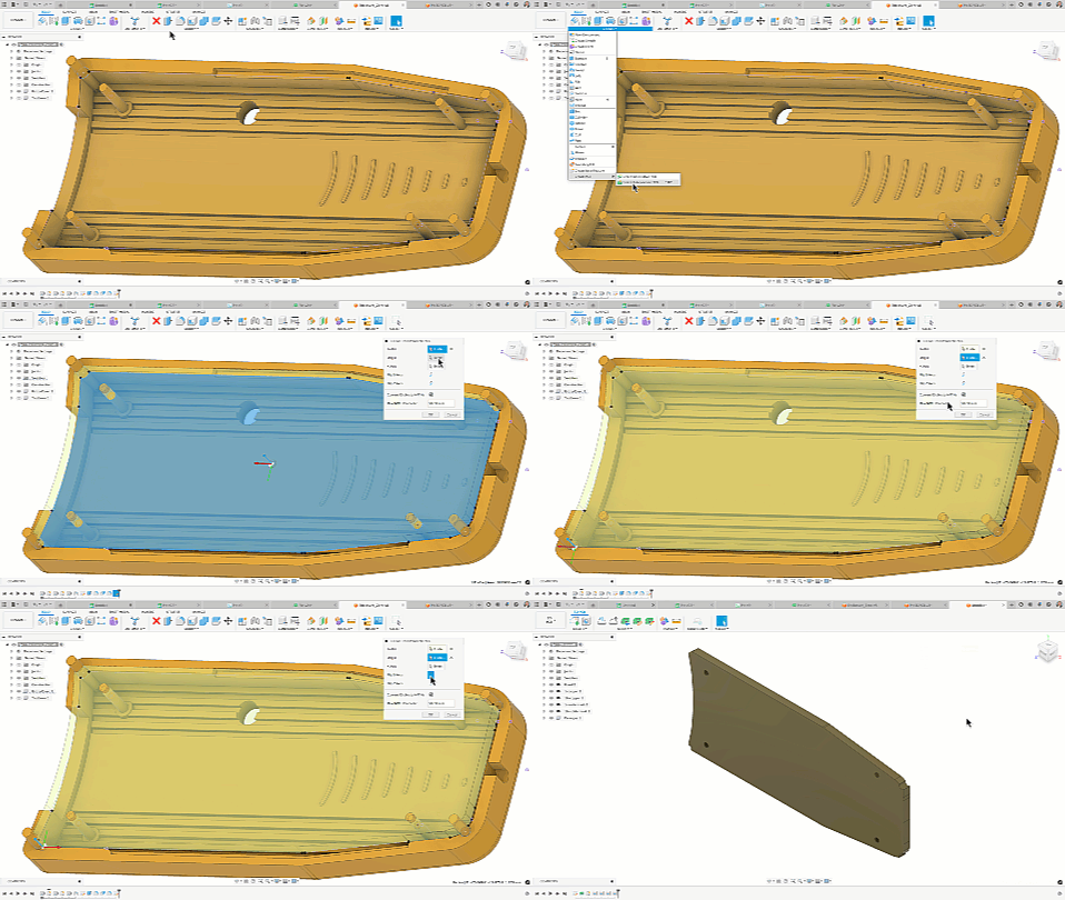
I will insert the PCB I created into my enclosure for our next step. This will allow us to draw the construction lines I need on the PCB before sending it to the 2D PCB workspace. Notice I insert the PCB from the Data Panel and use the point-to-point option to place it where I need the PCB to be.
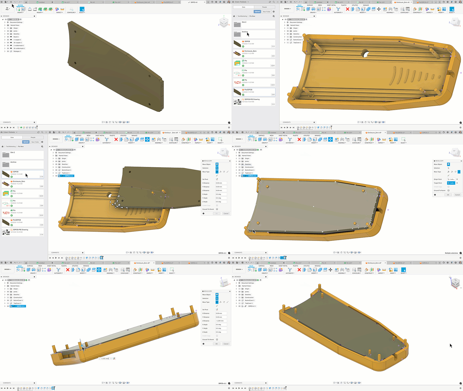
Edit-in place
Now that I have inserted the PCB into the enclosure, I will enable the Edit-In-Place option. This will allow us to draw the construction line references for the connectors that are placed on the PCB.
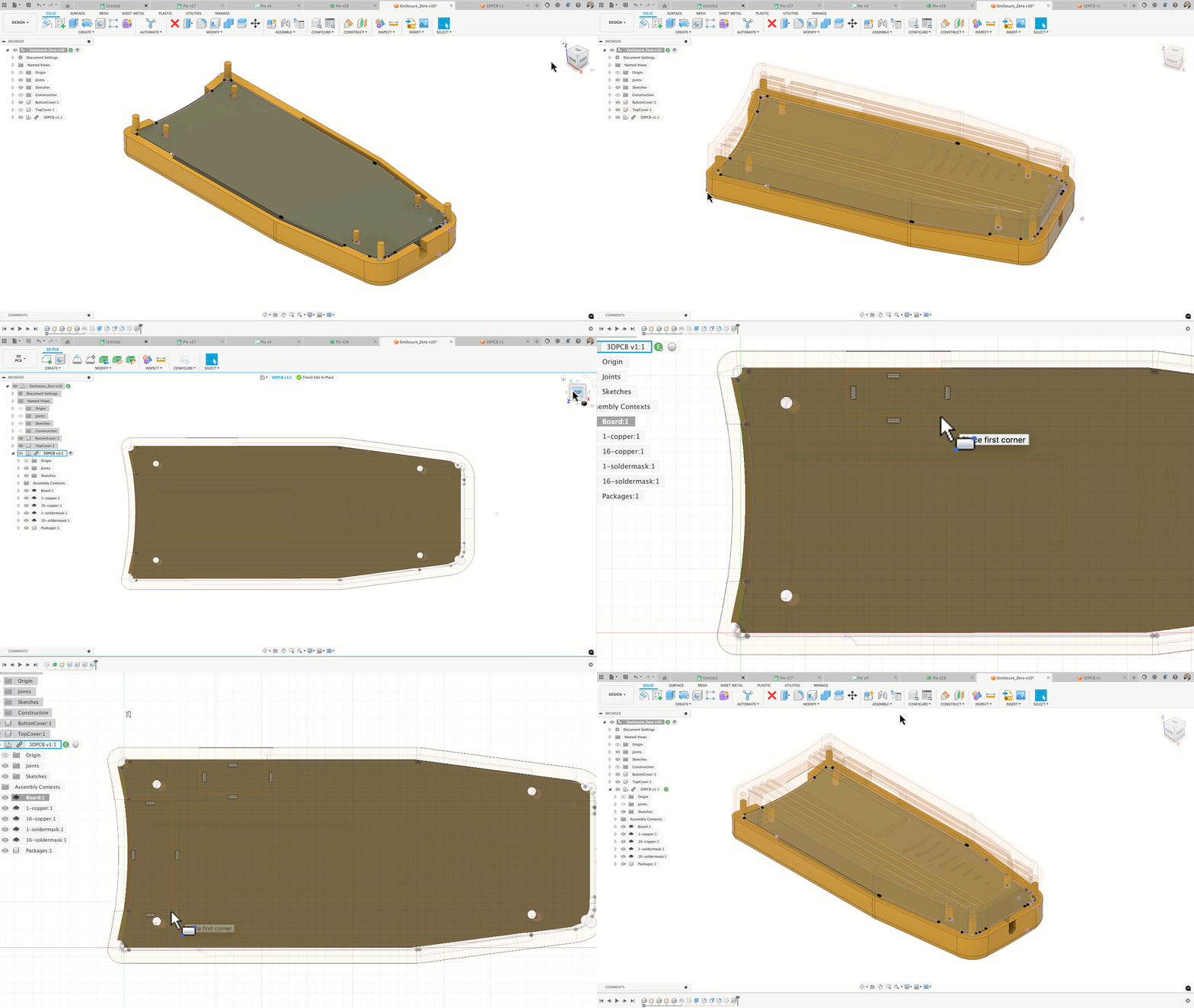
Snap Shot of the inserted construction lines:
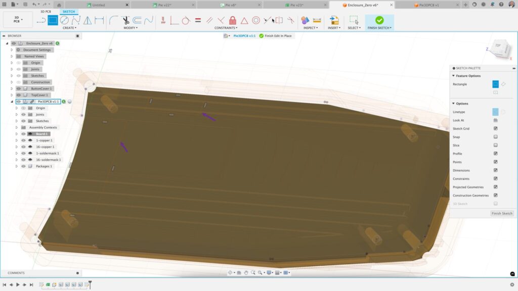
Now that the construction lines have been drawn on the PCB in the PCB sketch, we must go to the 3D PCB tab and synchronize the PCB model.
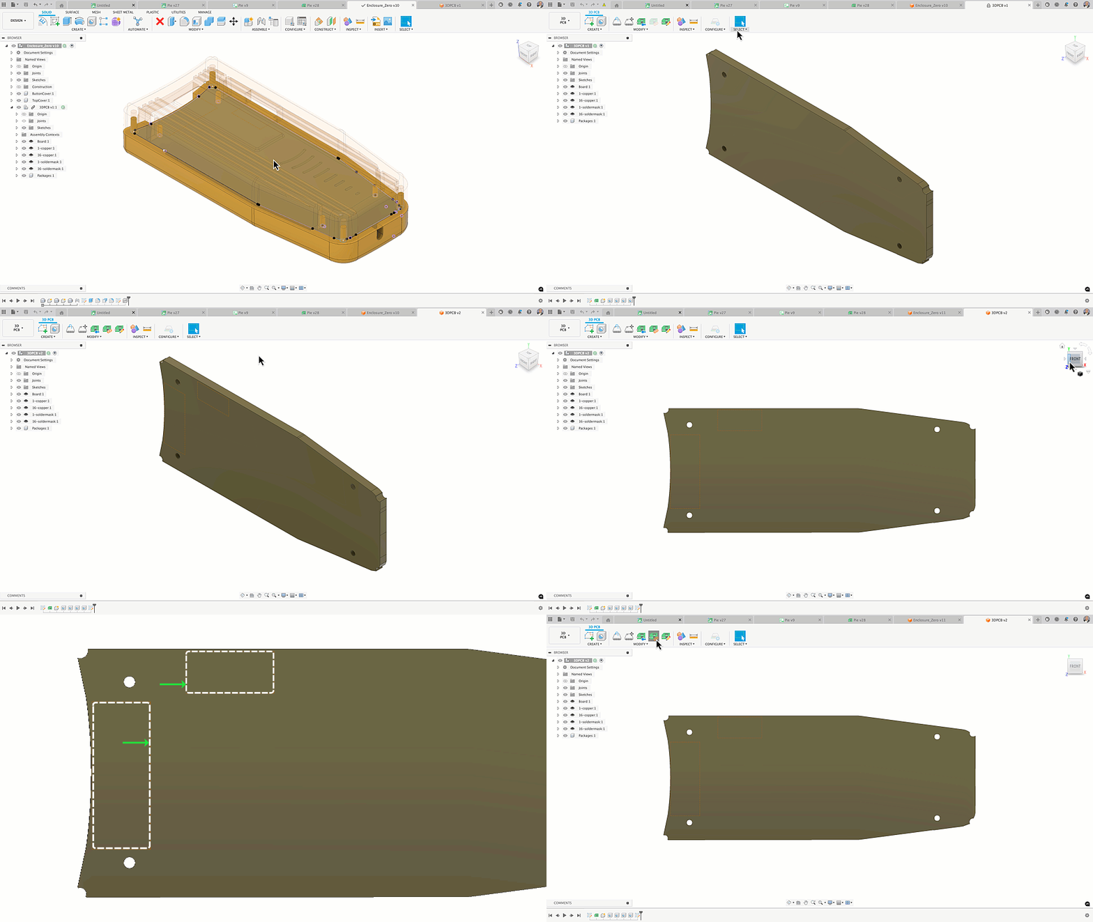
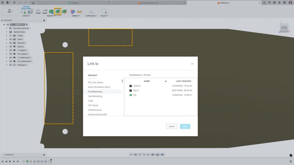
Now that the PCB in the design and the 3D PCB workspace are synchronized, I will assign this outline to the intended 2D PCB. The electronic engineer working in the Fusion Electronics workspace commonly performs this action. Select the icon in the 3D PCB workspace to link the 2D PCB. From the dialog box that appears, navigate and select the correct PCB. In moments, the 2D PCB will have the defined outline and the construction lines.
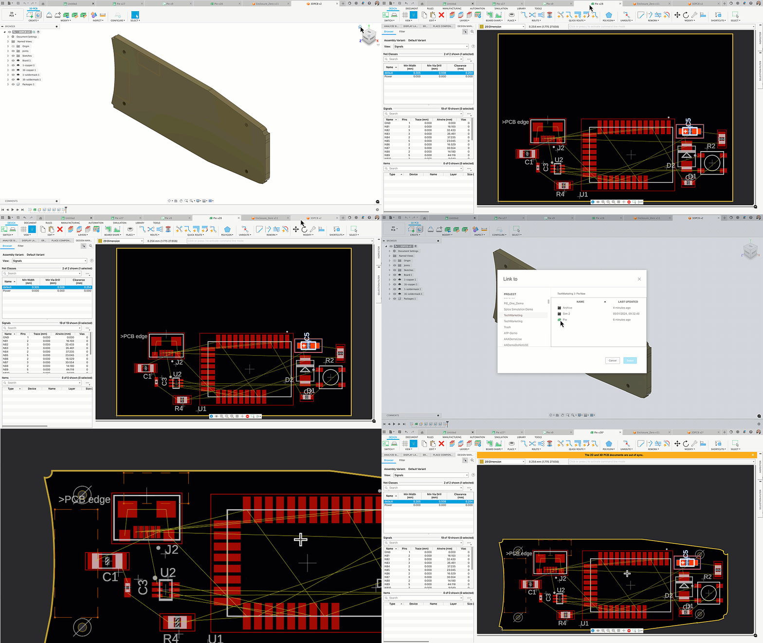
Notice that the Design Manager now has the PCB Sketches containing the construction lines. This allows you to reference the construction lines in the PCB layout.
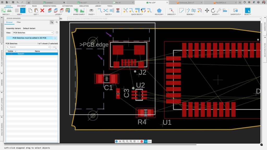
Now that we have Sketch data on our PCB, let’s move our connector within the construction line and synchronize our changes with the 3DPCB.
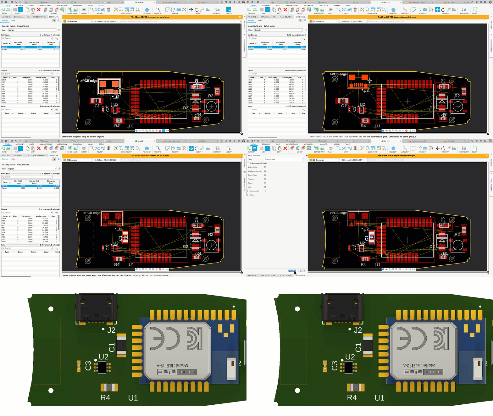
Our final step is to synchronize our assembly in the design workspace. You must first save your 3D PCB before proceeding to the design workspace.
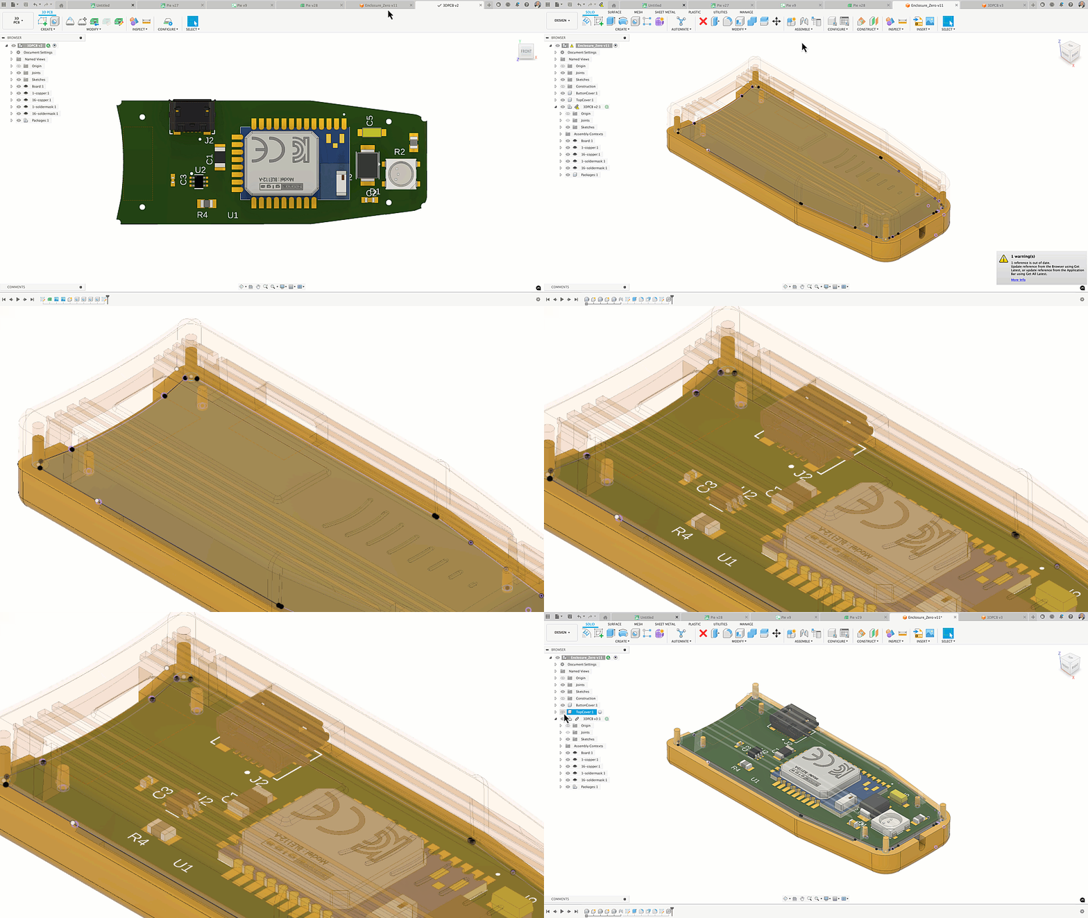
You will notice an alert at the top of the screen informing you of changes to a linked asset. After selecting the synchronization option, the PCB will now appear in the enclosure with all the 3D models of the components as it does in the 3D PCB workspace.
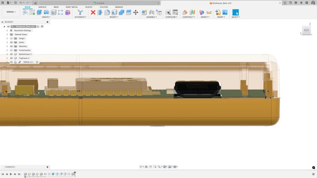
Construction lines in Autodesk Fusion
The value the capabilities of using construction lines to communicate flawlessly between your mechanical and electronic engineers is important. Getting it right with fewer prototype spins is the ultimate goal for all consumer product designers. With Fusion, we’ve found ways to master this. Why not try this today? Discover a new dimension of product design with Autodesk Fusion.