[toc]
In this up-coming update, we’re adding some major improvements to the Turning strategies, including the new Profile Roughing and Profile Finishing strategies. Within these two new strategies, there are a slew of new options such as Tangential Extensions and other improvements that take Fusion 360’s Turning capabilities to a new level, so let’s go through how you can soon take advantage of this new tech!
Note: The old profile turning strategies are no longer visible but they can still be edited, posted and copied between files or saved and reused as templates if you’re not quite willing to let them go yet.
Previously, both profile roughing and finishing were bundled in the same “Turning Profile” strategy — we’ve split them into two separate strategies in order to:
- Simplify the workflow by reducing complexity
- Simplify the interface and reduce clutter by removing parameters from roughing that did not apply to finishing and vice versa
- Allow roughing and finishing operations to use a separate tool, separate feeds and speeds and separate machining limits
Read more about the two new strategies that are coming soon in a September update below:
[icon name=”star” class=”” unprefixed_class=””] Tangential Extensions
(Profile Roughing and Finishing)
The Geometry tab for Profile Turning operations now supports tangential extensions for both profile roughing and profile finishing. This allows you to extend the turning profile geometry tangentially in either the front or the back by defining the front or back extension distance respectively. The extension distance is measured along the direction of the extension.

Tangential extensions are useful when you’re trying to machine extra material to make space for another tool, like towards the back for a parting tool to cut the part off. You can also use it to ignore certain profile features so that a different tool can be used to finish them.
[icon name=”star” class=”” unprefixed_class=””] Tool Limits
(Profile Rough and Finishing)
Also new in the Geometry Tab is the “Tool Limits” option for the back Z limit for both profile roughing and profile finishing. This parameter allows you to specify how the Z limit will be used with respect to the cutting tool. This fixes a few issues:
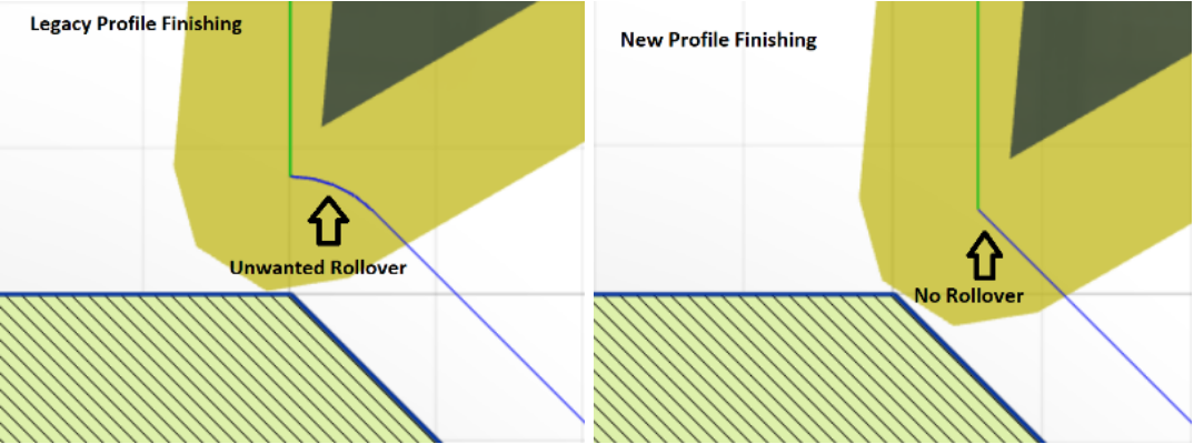
Fixes issue with tool-path “rollover” around outside corners: Previously the back Z limit was used to limit the center of the tool corner radius. The unwanted (and often unexpected) result of this was that you were unable to limit the tool from machining over outside corners and had to apply a correction to the back Z limit to avoid this behavior. The new parameter not only fixes this issue but also offers you two “Tool Limit” options on how to do it. Rad.

Cutting edge limit: The “Cutting edge” option in the back Z Tool Limits parameter allows you to use the back Z limit as a hard limit, preventing any part of the tool from violating this Z coordinate.
[icon name=”thumb-tack” class=”” unprefixed_class=””] Protip: The tool-path does not remove all the material up to the back Z limit and leaves a scallop, and it will remain independent of the type of tool used.
Contact point limit: The “Contact point” option in the back Z Tool Limits parameter allows the user to use the back Z limit by using it to constrain the contact point of the tool with the material.
[icon name=”thumb-tack” class=”” unprefixed_class=””] Protip: The toolpath removes all the material up to the back Z limit without leaving a scallop. The toolpath will also change depending on the corner radius of the selected tool and will remain associative with the tool in order to ensure that it removes all the material.
No more Retract Radius: The new strategies will not have a “Retract Radius” parameter in the Radii tab, thus simplifying the interface with one less parameter for the user to worry about.
Radial Tool Limits (Profile Finishing)
Cutting edge limit: Similar to the Tool Limit parameter for the back Z limit, the Tool Limit parameter in the Radii tab offers you The “Cutting edge” option allows you to use the inner radius for outside profiling and the outer radius for inside profiling as a hard limit, preventing any part of the tool from violating this X coordinate. The toolpath does not remove all the material up to the inner / outer radius and leaves a scallop. and will remain independent of the type of tool used.
Contact point limit: The “Contact point” option allows you to use the inner radius for outside profiling and the outer radius for inside profiling to constrain the contact point of the tool with the material. The toolpath removes all the material up to the inner / outer radius without leaving a scallop.It will also change depending on the corner radius of the selected tool and will remain associative with the tool in order to ensure that it removes all the material.
[icon name=”star” class=”” unprefixed_class=””] Canned Cycles
(Profile Roughing)
You can now use two roughing canned cycles, the G71 canned cycle for horizontal passes (machining parallel to the Z axis) and the G72 canned cycle for vertical passes (machining parallel to the X axis). Canned cycle output is turned on when the “Use Canned Cycles” parameter is checked. When canned cycle output is turned on the viewable tool path consists of two sections, the canned cycle toolpath: the canned cycle profile coordinates that will be sent to the post processor and the simulation toolpath: the long hand scan-line coordinates that will simulate the actual machining of the toolpath.
Canned cycle output is only available when:
- Rest machining is unchecked
- Cycle is set to horizontal or vertical
- For horizontal cycles when grooving is either set to no grooving or radial grooving
- For vertical cycles when grooving is either set to no grooving or axial grooving
If the controller only supports Type 1 canned cycle output then you have to set grooving to no grooving.
Canned cycle output is currently not supported when:
- Either the back Z tool limit is set to contact point or the radial tool limit is set to contact point
Variable X and Z finish allowances
- The post processor has to support the chosen canned cycle.
If the post processor does not support the canned cycle there will be an error generating the NC code.
[icon name=”star” class=”” unprefixed_class=””] In Control Compensation
(Profile Finishing)
In the Passes Tab, we’ve simplified compensation types by removing some options that were milling specific. Now, you will only see the turning specific options “In computer” for uncompensated toolpaths and “In control” for compensated toolpaths for when you want to adjust feature size at the machine.
When compensation type is set to “In Control”, the viewable toolpath (when seen from the “view toolpath” option in the right click menu) consists of two sections, the compensated toolpath: the partline coordinates that will be sent to the post processor and the simulation toolpath: the coordinates offset by the tool nose radius that will simulate the actual machining of the toolpath.
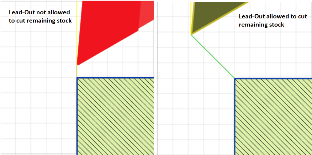
Protip: If compensation type is set to “In Control” but a lead out is not created due to a violation with the remaining stock then the user will receive an error message and the toolpath will not be generated. Most times when this happens, the situation can be remedied by checking the “Allow lead out to cut remaining stock” parameter in the Linking tab. This will allow the lead out to cut through the remaining stock and thus be created and maintain the integrity of the compensated NC program.
[icon name=”star” class=”” unprefixed_class=””] Linking Clearance Options
(Profile Roughing)
We updated the Clearance section of the linking tab as well.
Z Clearance: The tool approaches / clears the stock Z limit through this incremental Z distance.
X Clearance: The tool approaches / clears the stock X radius through this incremental X distance.
Retract Distance: This is the distance in Z for a vertical passes cycle and X for a horizontal passes cycle that the tool retracts through 45 degrees to clear the machined surface after every cutting pass.
[icon name=”thumb-tack” class=”” unprefixed_class=””] Protip: When tangential extensions are applied, the Z and X clearances are added to the end of the tangential extension.
[icon name=”star” class=”” unprefixed_class=””] Linking Tangential Lead Angles
(Profile Finishing)
The lead-in and lead-out angles for profile finishing are now always measured with respect to the direction of the toolpath (equivalent to the “Use Fixed Lead Direction” parameter in the legacy Turning Profile strategy being checked off).
[icon name=”star” class=”” unprefixed_class=””] Radial Extension
(Profile Finishing)
The Radial Extension parameter allows the toolpath cutting moves to be extended radially to the outer radius for outside profiling and the inner radius for inside profiling. This allows the tool to safely clear the stock after a profile finishing operation.
[icon name=”thumb-tack” class=”” unprefixed_class=””] Protip: Radial extensions will not be available when “Same as Lead-In” is selected for lead out type.
[icon name=”star” class=”” unprefixed_class=””] Predictable Lead Outs
(Profile Finishing)
The parameter “Allow Lead-Out to Cut Remaining Stock was added to the profile finishing linking tab. This parameter when checked off, will gouge-check programmed lead-out with the remaining stock back wall. If the lead-out is found to violate the back wall, it will return a non-fatal warning and adjust the angle of the lead-out so it does not gouge the back wall.
If the parameter is checked on, the lead-out will be allowed to violate the remaining stock back wall and be created at the angle it was programmed at.

We’re really pumped to get this out to you so you can level up your turning strategies. All of this will be included in the next product update, coming soon, so keep an eye out for that!
Cheers,