What is a scan to CAD workflow? Why is it becoming a popular method across various industries, such as automotive? In this article, we explore the benefits of a scan to CAD workflow.

Recreating the physical world within CAD software has become an important step in many design processes, especially in the aftermarket automotive industry. When designing automotive parts for an already-existing vehicle, accurately capturing physical objects in a digital representation is paramount.
Think about it — if you’re going to design a small part for an engine, wouldn’t it be helpful to design the part within the context of the engine itself? Or, if you’re redesigning a vintage steering wheel, wouldn’t it be helpful to work from the original steering wheel design instead of starting from scratch? Those are just two of many examples where a scan to CAD workflow might come in handy.
Moreover, these digitized objects must exist in an understandable and usable format so that designers can properly manipulate them. That’s where the proper CAD tool comes in handy.
What is a scan to CAD workflow?
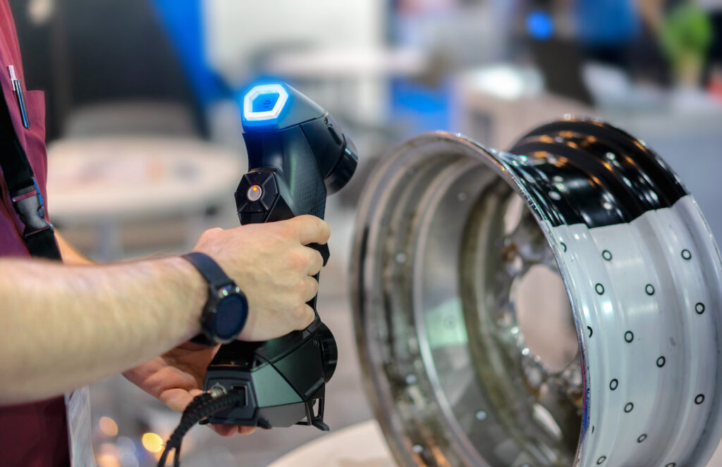
In simple terms, a scan to CAD workflow is exactly what it sounds like. It’s the process of scanning a physical object and inputting the data into CAD software. Teams can then either manipulate the data itself to turn it into a new product or create a new product that fits within the data’s environment.
Let’s explore the process in detail, including its benefits and challenges.
Challenges with scanning
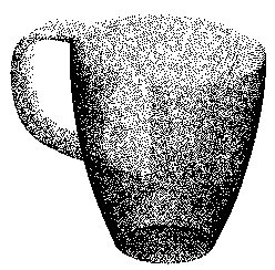
Scanning an object with a laser involves sweeping the focal point across the object’s surface, usually while rotating the object or moving the scanner. The sweep is discretized into uniform steps, and each step results in a singular measurement of a point location on the object’s surface. As shown in Figure 1 (below), the aggregation of all these individual points forms a cloud that more or less represents the scanned object.

Humans can easily interpret the points to recognize an object, however CAD software is unable to. This is because the human observer utilizes real-world context and experience to complete visual gaps left by the points in the cloud. In CAD terminology, one could say that humans can quickly convert the points into surfaces. This is the same conversion type that needs to happen digitally to make the object manipulatable as a CAD object.
Making Scan Data Usable
The first step required to work with any type of scan data is simply cleaning it up. This may involve removing errant points from the cloud, filling in holes, resampling, and any other point-based operations. Most scanning tools use software to filter and clean the raw scan data.
The second step is to convert from individual points to a mesh, where each point represents a vertex of a triangle or quadrilateral. Many scanning software platforms also include this capability but sometimes are limited to triangular meshes. Third-party tools such as TopoGun and ZBrush can be invaluable for re-topologizing a mesh into quadrilaterals.
Once the scanned model is cleaned and meshed, it can be directly imported into CAD software like Autodesk Fusion 360. Meshes can be referenced for constructing new solid geometry and interfaced for mating parts and assemblies. Meshes can also be directly exported for slicing and 3D printing if no further modifications or interactions need to be modeled.
From Mesh To Solid
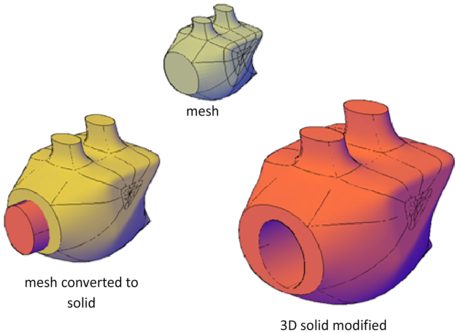
Often, the meshed scan is still inadequate for the design task at hand. A true 3D solid must be defined for making modifications, parametric features, or other more advanced CAD operations. As shown in the following figure, a quad mesh is converted to a solid and then cut with a cylinder tool.

Unfortunately, this step of the workflow is the most difficult and generally demands human skill and intervention. No tool can readily create spline or primitive-based solids directly from a mesh. Generally speaking, two techniques are used to achieve this type of transformation. The first is used if the model is relatively simple and composed of basic primitives to manually build the solid using the mesh as reference. The second technique applies to objects with complex surfaces and compound curves. The mesh is used as a reference, and cross sections are used as templates to create spline contours of the solid model. With either technique, solid bodies that represent the original scanned object with high fidelity can be realized. These solid bodies can be further modified and integrated into more complex models.
Scan to CAD with Fusion 360
Scan-to-CAD workflows can vary depending on the sophistication of the final product. For basic scanning and visualization, rendering a mesh model from the scanned point cloud may be sufficient. For more advanced manipulation and integration into 3D assemblies, the mesh may require promotion to a well-defined solid body. While this usually requires a significant amount of human intervention, Autodesk Fusion 360 offers a suite of mesh tools for slicing and referencing to make this task more manageable.
Ready to explore a scan to CAD workflow? Try Fusion 360 for free today.
