Schematic Basics Part 2:
How to Add Nets and Values to Your Symbols in Autodesk EAGLE
Welcome back! This is Schematic Basics Part 2. In our previous blog, we covered how to create your first schematic in Autodesk EAGLE and how to place symbols. In this blog, we’re going to take things a step further by learning how to add connectivity between your schematic symbols with the help of Nets. Then once everything is connected, we’ll cover how to add values to parts. Let’s get started!
First Things First
Like in Schematic Basics Part 1, there are a few details that we need to cover before soaking in some knowledge:
Use Nets, Not Wires
There are two kinds of wires in Autodesk EAGLE, the standard Wire, and the Net. But which do you use when creating connections between your symbols? Here’s how it works:
You don’t want to use the Wire ![]() icon when adding nets to your schematic. The only reason to use the Wire option is for adding detailed line drawings to your schematic.
icon when adding nets to your schematic. The only reason to use the Wire option is for adding detailed line drawings to your schematic.
You do want to use the Net ![]() icon to wire up your schematic symbols. This will always be your go-to action when you need to connect your symbols together.
icon to wire up your schematic symbols. This will always be your go-to action when you need to connect your symbols together.
This can be a tad confusing at first, but use the icon symbols as a visual guide. The Net icon is a green wire representing connectivity, which is exactly its purpose. Whereas the Wire icon has a line and a pencil. Use this feature, not the pencil for creating sketches.
Junctions and Overlaps
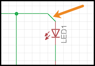
Next, you’ll need to understand the difference between junctions and overlaps. Here’s an example of a junction:

Be on the lookout for a node to identify net connection points.
You can always identify a junction by the large circle that connects two intersecting nets. This means that these nets are sharing an electrical connection. This is a universal symbol, so be on the lookout whenever you see it in any schematic down the road.
Now, when nets aren’t meant to share an electrical connection, then they will overlap. In Autodesk EAGLE, you’ll know when two nets are overlapping when there is no junction point between their intersection, like this:
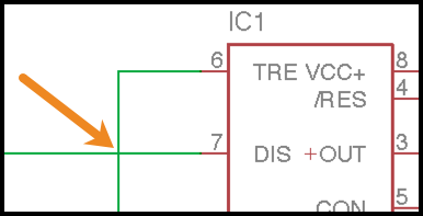
These nets don’t share an electrical connection, notice the lack of a junction point.
What’s so important about all of this? How you place your nets in your schematic will determine how your parts are electrically connected and will affect your PCB layout as well. If you don’t get this part right now, then your circuit won’t work as intended, and that’s no fun.
That’s it for the getting starting details. Let’s begin wiring up your schematic with nets!
Step 1 – Adding Your Grid
Before you go about adding any nets, let’s first add a grid to your schematic. This will make it a lot easier to see how all of our symbols are aligned and will let you easily see what course your nets will align with when placed. Follow these steps to turn on your grid
- Select the Grid
 icon in the top-left corner of your interface.
 - In the Grid Dialog, change the Display to On.
- All other settings can be left as is. Select OK to finalize your changes.
Turning on your grid will make a lot more sense once you start connecting nets, and it works much better than the blank white canvas with which that you started.
With the grid visible in EAGLE, it’s now easy to align and place nets.
Now that you have some structure in place with a grid let’s move on to connecting your symbols with nets!
Step 2 – Connecting Your Symbols with Nets
Connecting your symbols with nets is simple. Follow these steps to get started:
- Select the Net
 icon on the left-hand side of your interface.
 - Next, left-click at the end of the first pin from where you would like to start your net connection.
- Then, drag your mouse away from your first pin, and you should have a bright green net that follows your mouse along your grid lines.
- To finish the net, left-click on the end of another pin to make the connection. Your net will turn a dark green color let you know that it’s placed.
In our example shown below, we started with a simple net connection between the bottom of our R3 resistor and the top of our R4 resistor. Pretty easy? Now let’s find out how to add some junctions.

Resistors R3 and R4 now connected with a dark green net.
Step 3 – Adding Junctions to Your Nets
As we mentioned above, adding junctions to your schematic allows intersecting nets to share an electrical connection. To add a junction, you can do it in one of two ways:
Option 1 – Adding a Junction While Adding a Net
We need to add a net that connects between Pin 3 on our 555 timer and our R3 and R4 resistors. This will require a junction. You can follow these steps in our example to add one:
- Select the Net icon on the left-hand side of your interface.
- Next, left-click on the end of Pin 3 to start your net.
- Then left-click again in the middle of the R3/R4 net to finalize the connection, which will automatically create a junction.
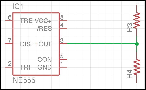
Pin 3 on the NE555 timer now has a junction connecting it to the net between R3 and R4 resistors.
Option 2 – Adding a Junction to an Existing Net
Creating a junction while adding a net is easy, but what happens if you have two intersecting nets that don’t already have a junction marker? You can add one manually:
- Select the Junction
 icon on the left-hand side of your interface.
 - Left-click on the intersecting point between two nets where you want to add a junction.
- This will open up the Connect Net Segments Dialog, confirming that you want to connect (merge) two nets. Select the desired net name and choose OK.
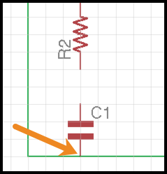
See that intersection point between our C1 capacitor and the net? It needs a junction added. Otherwise, no electrical connectivity will be shared.
Step 4 – Deleting Your Nets
You just added both regular nets and junctions, what happens if you make a mistake? Here is how to delete a net:
- Select the Delete
 icon on the left-hand side of your interface.
 - Left-click the segment of a net you want to delete, and it will be removed. If this net had a junction attached it will also be deleted.
Now you have all the basic building blocks you need to wire up your symbols. The completed schematic is below. Give it a try!
Note – You’ll notice that Pin 5 is not connected on this schematic. That’s done for a very good reason, which we’ll be exploring in Part 3 of this Schematic Basics series.
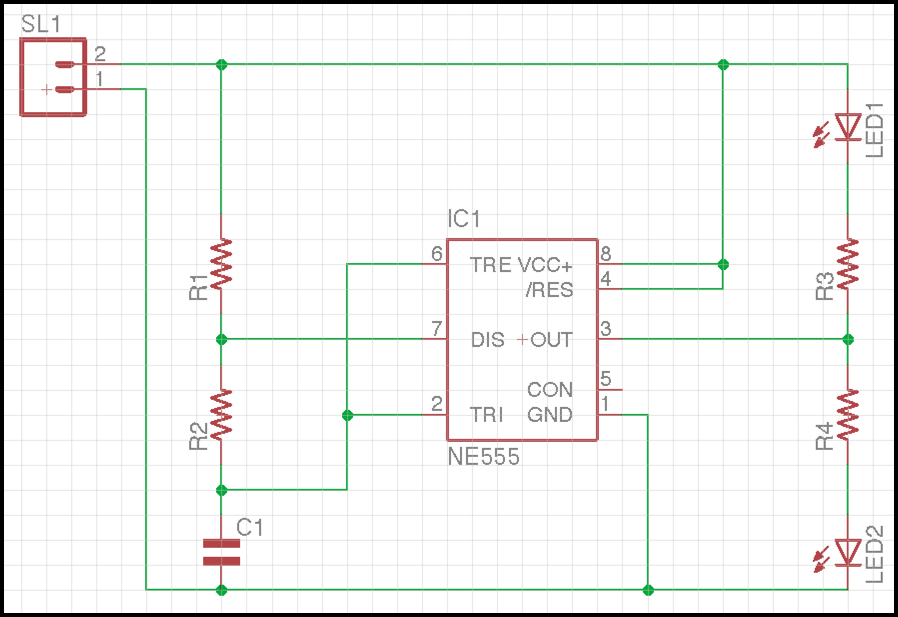
Our schematic circuit wired with all its nets, except Pin 5, but we’ll save that for later.
Optional- Net Angles
You might have noticed that when you select the Net ![]() icon, quite a lot of new options appear at the top of your interface. These options allow you to set a different bend radius on the net with which you’re working. By default, all of your net connections will use the Wire bend style 0, which is a 90-degree bend, which is fine for most schematics.
icon, quite a lot of new options appear at the top of your interface. These options allow you to set a different bend radius on the net with which you’re working. By default, all of your net connections will use the Wire bend style 0, which is a 90-degree bend, which is fine for most schematics.
However, you may want a 45-degree bend angle for your net. To do this, select the Wire bend style 1 and then add your net as described in Step 2 above. You’ll notice that the net will now automatically bend at your desired angle as shown below:
Here’s a 45-degree net made possible with Wire bend style 1.
There are a few other options in this menu, allowing you to add things like a custom radius, or even changing how the net line appears as either solid (continuous), dashed or dotted. Feel free to play around with these options to see how they make a difference. When you’re ready, let’s move on to the final step in today’s schematic journey, adding values to your symbols.
Step 5 – Adding Values to Your Symbols
Adding values to specific parts like your resistors, capacitors, etc. will make it easy your reference in the future. Here’s how to add values to your symbols:
- Select the Value
 icon on the left-hand side of your interface.
 - Left-click the symbol you want to add a value. In our example, we’ll choose our R1 resistor.
- In the Value Dialog, enter value 1k for your symbol and then select OK.
That’s all there is to it! As you can see in the image below, our R1 resistor now has a 1k value listed below its name. If you’ve been following along with our example circuit, then go ahead and add the remaining values for the three resistors and capacitor as well.
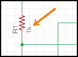
Our R1 resistor with its newly added 1k value.
Quick side note – If you also want to change the name of one of your symbols, it’s almost the same process as changing the value. The only difference being that you’ll select the Name ![]() icon instead of the Value
icon instead of the Value ![]() icon.
icon.
Step 6 – Deleting or Changing Your Symbol Values
Let’s say you need to delete or change a symbol value that you just added. You might be thinking to use the Delete action, but this will end up removing the entire symbol and value! This is definitely not what we want, so here’s the better way to do it:
- Select the Value icon on the left-hand side of your interface.
- Left-click the name of the value that you want to remove or change.
- In the Value Dialog that opens, you can either delete the name to remove it or change it.
- Once your change is made, select OK.
Mission Accomplished
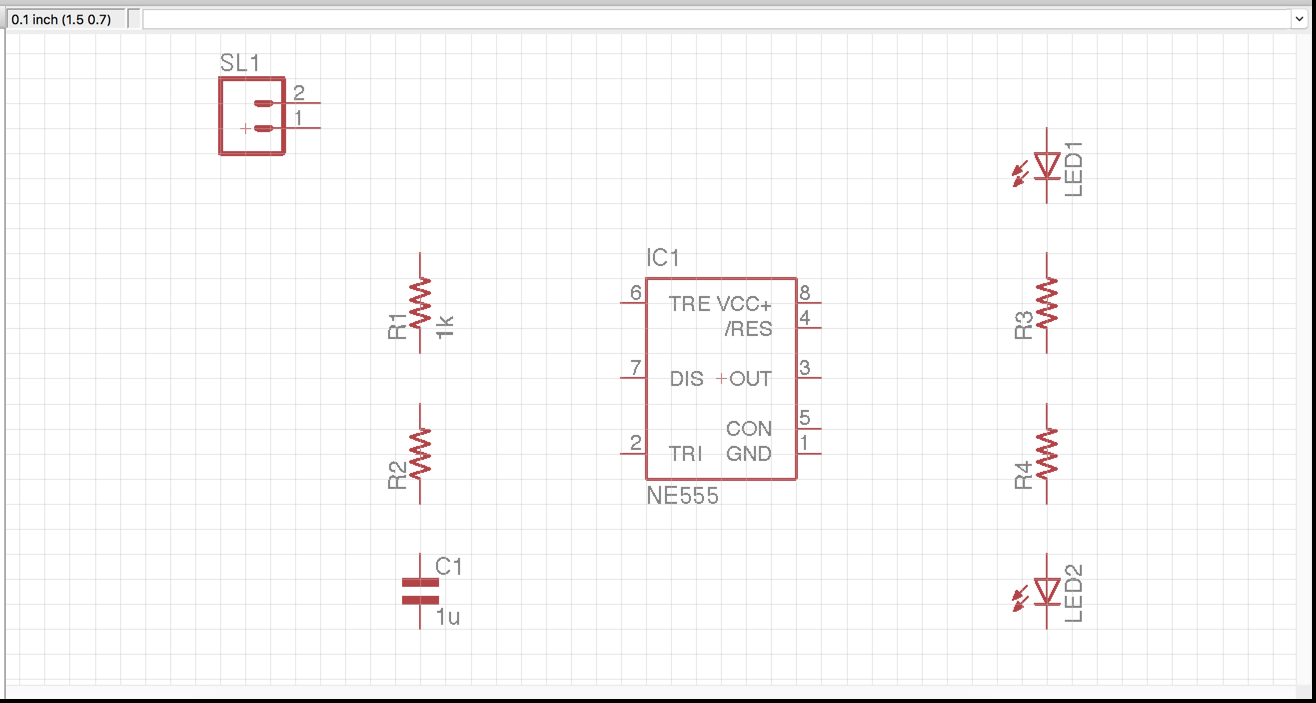
You did it! Your schematic should now be fully wired with a set of values added for all of the parts that needed it. Here’s how your schematic should look completed:
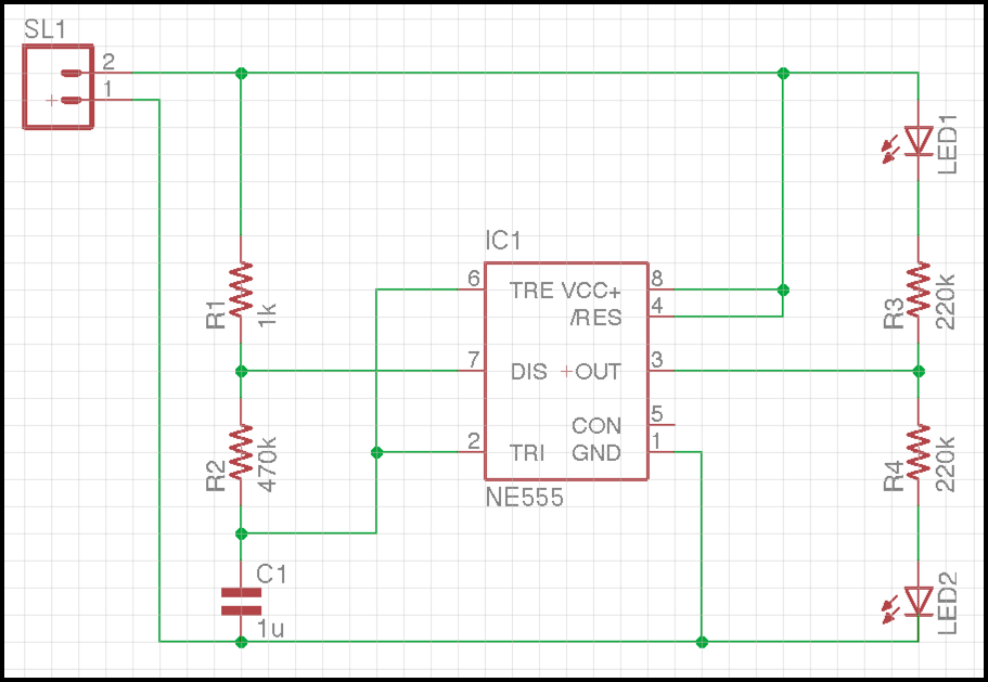
Our completed schematic, including all needed nets and values. Don’t mind Pin 5; it’s going to help us in Part 3 of Schematic Basics!
This brings us to the end of Schematic Basics Part 2, so let’s take a moment to recap the major concepts you learned today:
- Junctions & Overlaps – First, you learned the big difference between junctions and overlaps, and how a junction adds electrical connectivity between two intersecting nets, whereas an overlap shares no connectivity.
- Nets – You also learned everything there is to know about working with nets and junctions. This process always includes drawing a net from pin to pin and adding junctions where nets need to share electricity.
- Values – And last but not least, you learned how to add values to your symbols. You also learned how to change and delete a symbol’s value.
You might think you’re done with your schematic, but there’s one last step to be done! Read the next blog, Schematic Basics Part 3 to learn how to confirm that you’ve wired everything correctly with an Electrical Rule Check (ERC).
Making your first schematic in the free version of EAGLE is just the tip of the iceberg! Get the full experience today and upgrade now to Autodesk EAGLE with a monthly or yearly subscription.
See you next time.