Schematic Basics Part 3:
Checking Connectivity Errors with an ERC in Autodesk EAGLE
Greetings and welcome back to Schematic Basics Part 3! If you have been following along on our journey so far, then you know that we are closing in on the end of the road for your schematic journey. There’s one last step before you can check off on your schematic design and move onto your PCB layout – checking for connectivity with an Electrical Rule Check, or ERC. Let’s do it.
What is ERC?
If this is your first time designing a schematic then the term Electrical Rule Check might be a bit new. This is a handy little tool that you’ll always want to keep in your engineering toolbox, as it helps to point out common errors in your schematic. An ERC will check for the following issues:
- Are all of your nets properly connected and labeled on your schematic?
- Do you have any conflicting outputs/inputs on your schematic?
- Are there any open or overlapping pins and ports on your schematic?
You can think of an ERC as a second pair of eyes; it will always be there to help you find the missing details that you may have overlooked! Of course, an ERC is not meant to be a replacement for reviewing your schematic manually, so don’t rely on it as your first level of defense.
Types of ERC Errors
When you run an ERC for the first time, you’ll be presented with several error categories, including:
Consistency Errors: ![]() This error means that something isn’t right between your schematic and PCB layout, and your changes likely aren’t in sync between both files. If you get one of these errors, consider it a major red flag to compare both versions of your design before moving ahead.
This error means that something isn’t right between your schematic and PCB layout, and your changes likely aren’t in sync between both files. If you get one of these errors, consider it a major red flag to compare both versions of your design before moving ahead.
Errors: ![]() Errors are the red stoplights. You need to step on the breaks and check these out before proceeding. Errors can be pretty significant, like having an unconnected pin that will throw your whole circuit out of whack.
Errors are the red stoplights. You need to step on the breaks and check these out before proceeding. Errors can be pretty significant, like having an unconnected pin that will throw your whole circuit out of whack.
Warnings: ![]() Warnings are the yellow stoplights. While these types of errors might not mess up your design if you move forward without fixing them, it’s good practice to slow down and review them one by one. These guys are minor compared to Errors, and n include many non-design breaking issues like missing net values.
Warnings are the yellow stoplights. While these types of errors might not mess up your design if you move forward without fixing them, it’s good practice to slow down and review them one by one. These guys are minor compared to Errors, and n include many non-design breaking issues like missing net values.
With those details out of the way, let’s jump into your schematic and get started!
Note – If this is your first time joining us on our Schematic Basic Series, then welcome! We’re working on a simple LED Flasher that includes a 555 timer and some basic components. Here’s our schematic in its current shape. Go ahead and replicate it on your end so you can follow along with us.
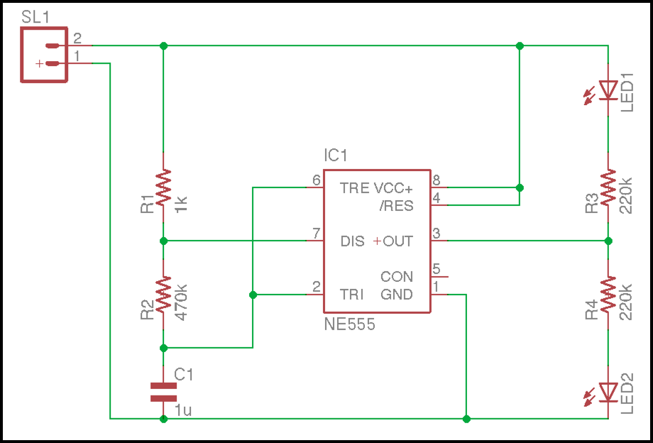
Our completed schematic of an LED Flasher from Schematic Basics Part 2. Make note of the missing net on Pin 5, that’s intentional!
Step 1 – Running Your First ERC
Running your very first ERC is super simple and won’t require any existing setup. Follow these steps to get going:
- Open your schematic in Autodesk EAGLE.
- On the left-hand side of your interface, select the ERC
 icon. You can also select Tools » ERC, whichever is easier for you.
This will open the ERC Errors Dialog, as shown below. As you can see there’s a whole lot of warnings and one error to review in our schematic. Before moving forward and fixing these, let’s review how this ERC Errors Dialog works.
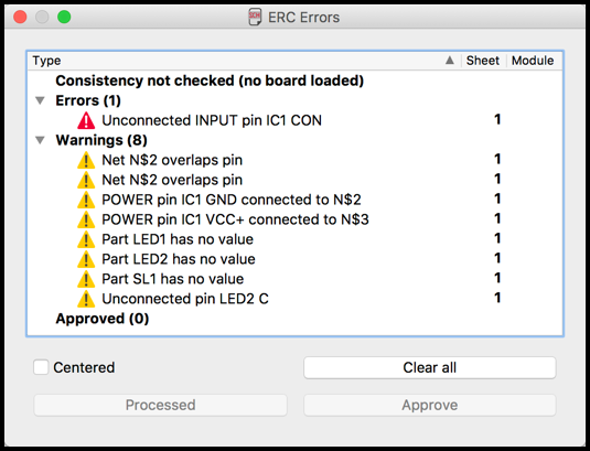
The ERC Errors Dialog – You will rely on this tool heavily in your engineering career.
Showing Errors in Your Schematic
By selecting one of the listed ERC errors you’ll notice that a black line and box will appear on your schematic, showing the exact location of the error. For example, in our image below when we select the error for an unconnected input pin you’ll notice that it zooms over to Pin 5 on our schematic, which is the pin we intentionally didn’t connect in Schematic Basics Part 2!
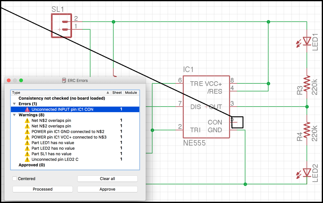
Selecting an error in the ERC Errors Dialog allows you to easily see where the error is located on your schematic. Note the black line and box around Pin 5.
Want to see your errors close up? Select the Centered checkbox on your ERC Errors Dialog and then select an error. It should zoom in to that specific issue on your schematic showing you the specific problem item. This is handy when your schematics become more complex.
Processing Errors
The three buttons available on the ERC Errors Dialog are all related to how you want to process the errors on your schematic. Here’s how they work:
- Clear All – Selecting this button will remove all of the issues listed on your errors report. Keep in mind that if you select Clear All and haven’t actually fixed anything, the next time you run your ERC all of the errors will reappear.
- Processed – Selecting this button will gray out the icon of an error that you have selected. This comes in handy if you need a way to visually mark that you have fixed an error before running your ERC again.
- Approve – Selecting this button will move a selected error into the Approved category at the bottom of your ERC Errors Dialog. This is a handy feature if there’s a specific error or warning that you don’t need to fix, and you simply want to remove it from your list of to-do’s.
One thing to note, just because you mark an error as processed or approved in the ERC Errors Dialog does not mean that EAGLE knows it’s fixed. To confirm that an error has been fixed you need to close and reopen the ERC Errors Dialog and EAGLE will check your schematic again in full.
Ok, that’s enough of an explanation for how the ERC Errors Dialog works, let’s start fixing all of the errors in your schematic!
Step 2 – Fixing Your ERC Errors
Keep in that mind our set of errors might differ slightly from yours. In this part, we’ll go through some of our errors one-by-one to show you how we troubleshoot our way through our schematic, and you can do the same!
Error 1 – Unconnected INPUT pin IC1 CON
Here’s the first error, but what does it mean? Selecting the error in your ERC Errors Dialog should take you to Pin 5 on your NE555 Timer, which is clearly unconnected! Now, before running off to connect that pin to ground, the TI NE555 Timer Datasheet has a hint of what you need, it says:
A Decoupling CONTROL voltage to ground with a capacitor can improve operation. This should be evaluated for individual applications.
Cool, so what that means is that you need to add a capacitor to your schematic before connecting any nets, here’s how:
- Select the Add
 icon on the left-hand side of your interface.
 - In the ADD Dialog, search for “electrolytic capacitor.”
- Select the first available capacitor listed in the rcl > EL – folder.
- Select OK and place this capacitor on your schematic between Pin 5 and your ground net.
- Next, select the Net
 icon on the left-hand side of your interface and connect Pin 5 to the top of the capacitor, then connect the bottom of the capacitor to the ground net below it.
 - Last, select the Value
 icon on the left-hand side of your interface and left-click your newly placed capacitor to give it a value of “10n.”
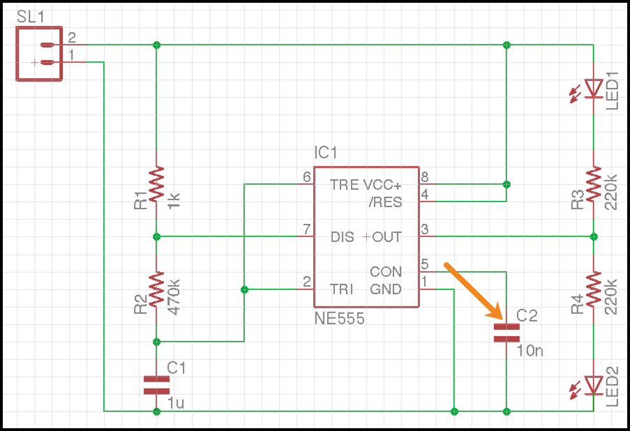
The updated schematic with the newly added C2 capacitor, completing the connection to Pin 5!
Ok, that should take care of that error. Close your ERC Errors Dialog, then reopen it and see what happens. Aha! That error is gone, and now we can move on to our warnings.
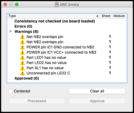
One less error in our life! Adding a second capacitor took care of the unconnected pin 5 issue.
Step 3 – Fixing Your ERC Warnings
We won’t go into complete detail on how to fix all of the warnings, simply for the sake of time. But let’s take a look at a few to give you an idea of what they mean and how to fix them.
Parts with No Values
There are several parts in the ERC Errors Dialog that have no value, including LED1, LED2, and SL1. These should be pretty simple to fix. Here’s how you can take care of LED1:
- Select the Value
 icon on the left-hand side of your interface.
 - Left-click on LED1 to open the Value Dialog.
- Enter a new value of “Red” and select OK.
You can repeat this process for LED2, giving it a “Red” value. The SL1 connector will most likely be hooked up to a 9v battery with some clips, so you can give that a value of “9v.” Go ahead and close your ERC Errors Dialog again, then reopen it and you should have three less warnings to worry about!
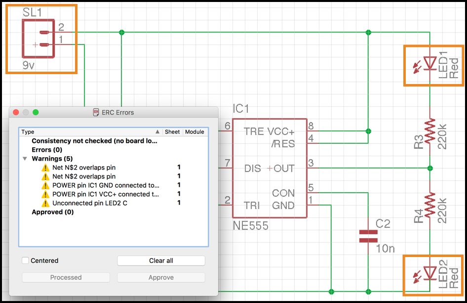
Here’s an updated schematic, notice the added part values for LED1, LED2, and SL1. 3 warnings down!
Unconnected Pin
Here’s an interesting one – Unconnected pin LED2 C. Now, if you wired up your schematic correctly in Schematic Basics Part 2, then you won’t have this error, but apparently we messed up!
If we zoom in to the bottom pin of LED2 then we can find the problem. See how the green line is darker next to the bottom of the pin in the image below? That means it’s not connected properly to the LED2 pin and is actually overlapping it.
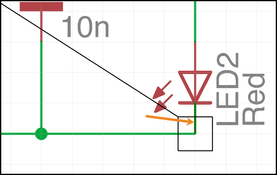
Check out the overlapping pin that we missed, shown in dark green. We can fix this by deleting the net and adding it again.
This is a simple fix, we just need to delete the existing net with the Delete icon, then rewire it with the Net icon. And with a quick closing and reopening of our ERC Errors Dialog, the problem is solved.
The Last Two Warnings
The last two warnings are a bit cryptic, so let’s look at the first – POWER pin IC1 GND connected to N$2. Let’s piece this out:
- POWER pin IC1 GND. This is a fancy way of saying Pin 1 on your NE555 Timer. Check out Pin 1 and you’ll see GND to the left of it, which is the ground pin.
- N$2. Now what in the world is this? That’s actually the name of the net that connects to Pin 1. EAGLE automatically assigns net names unless you change them, and every net will start with N$, then a number. Ours is N$2, but yours might have a different number.
So, the problem is that there’s a ground pin on this timer that EAGLE is expecting to be connected to a net called GND, but instead it’s called N$2. You can quickly fix this by changing the name of the N$2 net to match the name of Pin 1. To do this:
- Select the Name icon on the left-hand side of your interface.
- Left-click the N$2 net to open the Name Dialog.
- Enter the new name “gnd” and select OK.
Go ahead and do the same set of steps for your other issue, which should be a naming problem with your power net and Pin 8 (VCC+) on your NE555 timer. After that, close and reopen your ERC Errors Dialog, and you should be error free.
P.S. Struggling to find the right net on your schematic? Select the Show ![]() icon and left-click on any net on your schematic. You’ll see the name of the net displayed in the lower left corner of your interface as shown below.
icon and left-click on any net on your schematic. You’ll see the name of the net displayed in the lower left corner of your interface as shown below.
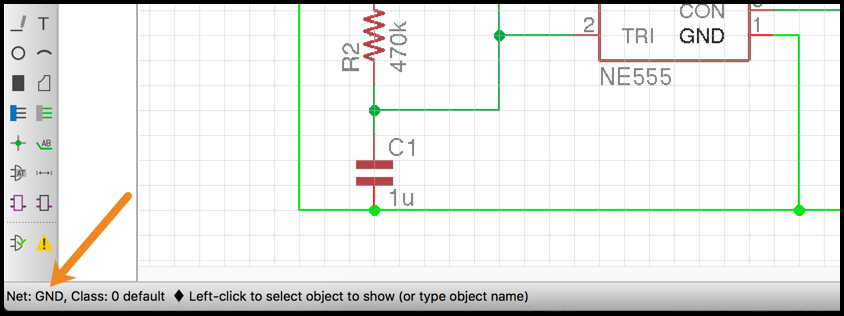
An easy way to figure out the name of a net with help from the Show action.
Error Free Is the Way to Be!
Well, it’s official, your schematic is now error free and complete! Give yourself a round of applause, this was quite the journey. If you ever get stuck on connecting pins in an integrated circuit like our NE555 timer, then be sure to look up a datasheet to get some guidance. With your schematic done, it’s now time to transform your idea into a physical PCB layout! This is where things really start to come alive. Be on the lookout soon for our PCB Layout Basics series, coming soon!
Making your first schematic in the free version of Autodesk EAGLE is just the tip of the iceberg! Get the full experience today and Subscribe to Autodesk EAGLE.
Until we meet again in the PCB layout, keep designing!