& Construction

Integrated BIM tools, including Revit, AutoCAD, and Civil 3D
& Manufacturing

Professional CAD/CAM tools built on Inventor and AutoCAD
5 min read
Here’s everything You Need to Know About Schottky Diodes. Learn how Schottky diodes work in RF circuits, generators, and motor drivers with their low forward voltage drops and fast switching speeds.
Like other diodes, the Schottky diode controls the direction of current flow in a circuit. These devices act like one-way streets in the world of electronics, letting current pass only from anode to cathode. However, unlike standard diodes, the Schottky diode is known for its low forward voltage and fast switching ability. This makes them an ideal choice for radio frequency applications and any device with low voltage requirements. There are a variety of uses for the Schottky diode, including:
One of the primary advantages of using a Schottky diode over a regular diode is its low forward voltage drop. This allows a Schottky diode to consume less voltage than a standard diode, using only 0.3-0.4V across its junctions. In the graph below, you can see that a forward voltage drop of about 0.3V begins to increase current significantly in a Schottky diode. This current increase would not take effect until about 0.6V for a standard diode.

In the images below we have two circuits to illustrate the benefits of a lower forward voltage drop. The circuit on the left contains a conventional diode, and the one on the right is a Schottky diode. Both are powered with a 2V DC source.

The conventional diode consumes 0.7V, leaving only 1.3V to power the load. With its lower forward voltage drop, the Schottky diode consumes only 0.3V, leaving 1.7V to power the load. If our load required 1.5V then only the Schottky diode would be up for the job.
Other advantages for using a Schottky diode over a regular diode include:
There are some disadvantages to keep in mind about Schottky diodes. A reverse-biased Schottky diode will experience a higher level of reverse current than a traditional diode. This will lead to more leaked current when connected in reverse.
Schottky diodes also have a lower maximum reverse voltage than standard diodes, usually 50V or less. Once this value is exceeded then the Schottky diode will break down and start to conduct a large amount of current in reverse. However, even before reaching this reverse value the Schottky diode will still leak a small amount of current like any other diode.
A typical diode combines p-type and n-type semiconductors to form a p-n junction. In a Schottky diode metal replaces the p-type semiconductor. This metal can range from platinum to tungsten, molybdenum, gold, etc.
When metal is combined with an n-type semiconductor an m-s junction is formed. This junction is referred to as a Schottky Barrier. The behavior of the Schottky Barrier will differ depending on whether the diode is in an unbiased, forward-biased, or reverse-biased state.
In an unbiased state, free electrons will move from the n-type semiconductor to the metal in order to establish balance. This flow of electrons created the Schottky Barrier where negative and positive ions meet. Free electrons will need a greater supplied energy than their built-in voltage to overcome this barrier.

Connecting the positive terminal of a battery to the metal and the negative terminal to the n-type semiconductor will create a forward-biased state. In this state, electrons can cross the junction from n-type to metal if the applied voltage is greater than 0.2 volts. This results in a flow of current that’s typical for most diodes.

Connecting the negative terminal of a battery to the metal and positive terminal to the n-type semiconductor will create a reverse-biased state. This state expands the Schottky Barrier and prevents the flow of electric current. However, if the reverse bias voltage continues to increase this can eventually break down the barrier. Doing so will allow current to flow in the reverse direction and may damage the component.

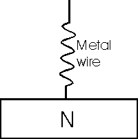
There are a variety of methods to manufacture a Schottky diode. The simplest is to connect a metal wire against a semiconductor surface, called Point Contact. Some Schottky diodes are still manufactured using this method, but it is not known for its reliability.

The most popular technique is using a vacuum to deposit metal onto the semiconductor surface. This method presents an issue of the metal edges breaking down due to the effects of electric fields around the semiconductor plate. To remedy this, manufacturers will protect the semiconductor plate with an oxide guard ring. Adding this guard ring helps to improve the reverse breakdown threshold and prevents the junction from being physically destroyed.
Planning to work on an RF or power application that requires low-voltage operation? Schottky diodes are the way to go! These diodes are well known for their low forward voltage drop and quick switching speeds. Whether they’re used in solar cells or power rectification, you can’t beat the low 0.3V voltage drop and added efficiency. Autodesk EAGLE already includes a ton of free Schottky diode libraries ready to use. No need to make your own. Download Autodesk Fusion for free today!
By clicking subscribe, I agree to receive the Fusion newsletter and acknowledge the Autodesk Privacy Statement.
Success!
May we collect and use your data?
Learn more about the Third Party Services we use and our Privacy Statement.May we collect and use your data to tailor your experience?
Explore the benefits of a customized experience by managing your privacy settings for this site or visit our Privacy Statement to learn more about your options.