& Construction

Integrated BIM tools, including Revit, AutoCAD, and Civil 3D
& Manufacturing

Professional CAD/CAM tools built on Inventor and AutoCAD
19 min read

V.2.0.11186
Manufacture
We fixed a crash issue that was occurring in certain turning profile roughing tool-paths with cycle set to vertical passes and rest machining checked.
A few of you reported that if you had “operation ordering for nested patterns” turned on, manufacturing setups with mirrored patterns either didn’t post correctly or caused Fusion 360 to crash. This is now fixed and you no longer have to turn off the option “operation ordering for nested patterns”.
Drawing
One of you reported a “Fatal Error: Unhandled e06d7363h Exception at D3DB4F99h” error message when attempting to open or create a drawing. This is now fixed.
V.2.0.11183
New! Edit-in-Place now supports Sheet Metal tools

Edit-in-Place has come a long way, and we are continuing to tie in important capabilities that will enable you to execute true Bottom-Up design workflows. In this update, we’re happy to say that Edit-in-Place workflows now support Sheet Metal functionality. Right-click on a referenced sheet metal part in your browser and you’ll be able to “edit it in place”, right within context of the overall assembly document. This includes Convert to Sheet Metal, sheet metal rules, Flange, Bend, and Unfold/Refold tools (Create Flat Pattern is not supported yet).
Learn more about Edit In Place
Improved! Surface Patch creation

For those of you who are surfacing nerds – check this out. We upgraded our surfacing algorithm that now the transitions between the original surface and patched surface have greatly improved. Also, previous surface patches that weren’t behaving nicely now should behave a lot more to what you’d expect. This may not seem much on the surface (no pun intended), but it is an important step in laying the groundwork for future enhancements we’re planning to bring to the surfacing environment of Fusion 360 (it’s gonna be awesome).
Improved! Save As Mesh now supports OBJ

Now when you right click on a mesh body and select Save as Mesh, you’ll have the option to pick OBJ as the file format type to save as. You are now also able to select multiple mesh bodies when tessellating, as well as Create Component from mesh bodies when working in Edit-in-Place mode.
Learn more about saving mesh bodies as 3MF, OBJ, or STL files
New in Preview! Fluids Study Type
Preferences > Preview Features > Generative Design > Fluid Path

Now available to try as preview functionality is a brand new study type in Generative Design. This is the first time where new capabilities for exploring design ideas/alternatives for fluid flow applications will be available to try within Fusion 360.
Following existing Generative Design workflows and concepts you’re already familiar with, we’ve implemented Fluid in a way that is focused on delivering an efficient fluid path design while minimizing pressure drop. The outcome in this first public preview will be a single fluid path geometry that can be used in downstream design and simulation work. As the solution matures toward commercialization, we will enable more engineering design criteria like flow balancing and mixing.
To try this preview functionality, to the Preview Features section in your preferences and check the “Fluid” checkbox under Generative Design.
Learn more about the Fluid Path study
New! Package generator type – SMD Header Right Angle (Male)
File > New Electronics Library > Create New Package
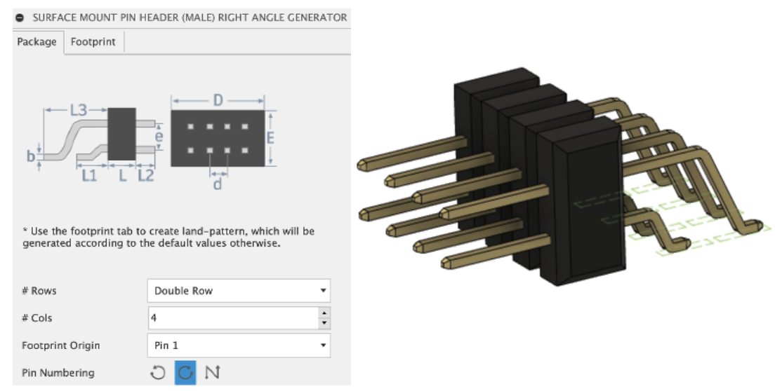
We have added a new package type, Surface Mount Male header (Right Angle) which supports single & dual row along with customized footprint (non-ipc derived). They are generally used in board stacking application by connect PC board-board without a cable (by mating with a receptacle connector).
New! New library parts – IC_Embedded, Sensor
File> New Electronics Design > New Schematic > Add part
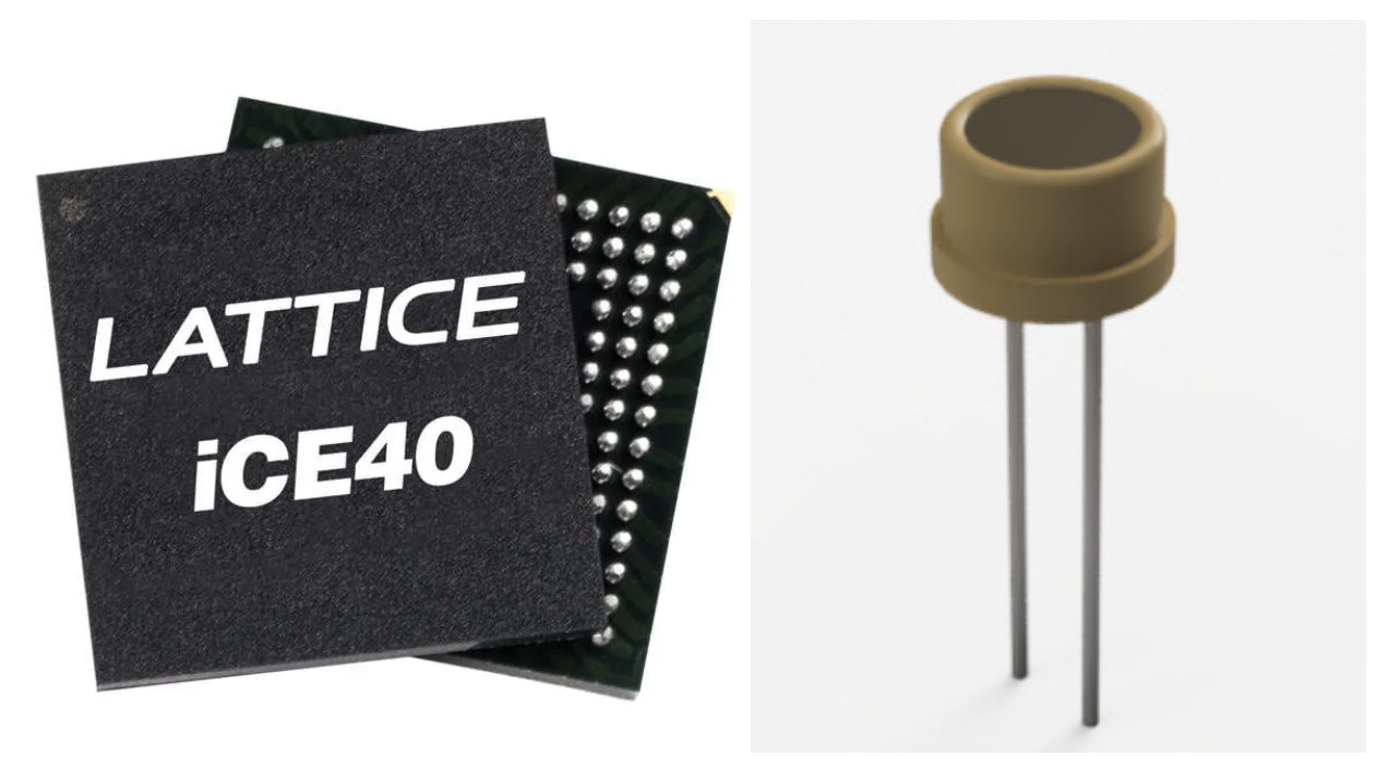
In this release we have added popular 8, 16 and 32-bit microcontrollers to IC_Embedded library. Also, iCE40 LP family FPGA was added from Lattice which is intended for ultra-low power applications in portable devices like wearables. In addition to that we also added battery charger IC’s, LED drivers and couple of sensors like Accelerometer, Gyro, Photocell etc.
Improved! Added images in footprint tab for all Thru hole types for better visualization.
File > New Electronics Library > Create New Package
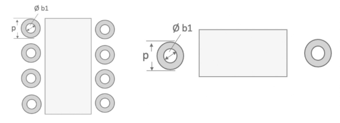
We have added separate images in the Package generator footprint tab for each package according to their type. Though there is no functionality change, this improvement will help to easily visualize the package than the older version that only has pad and hole detail.
Improved! Dimensions units can now be in ft, m, and cm
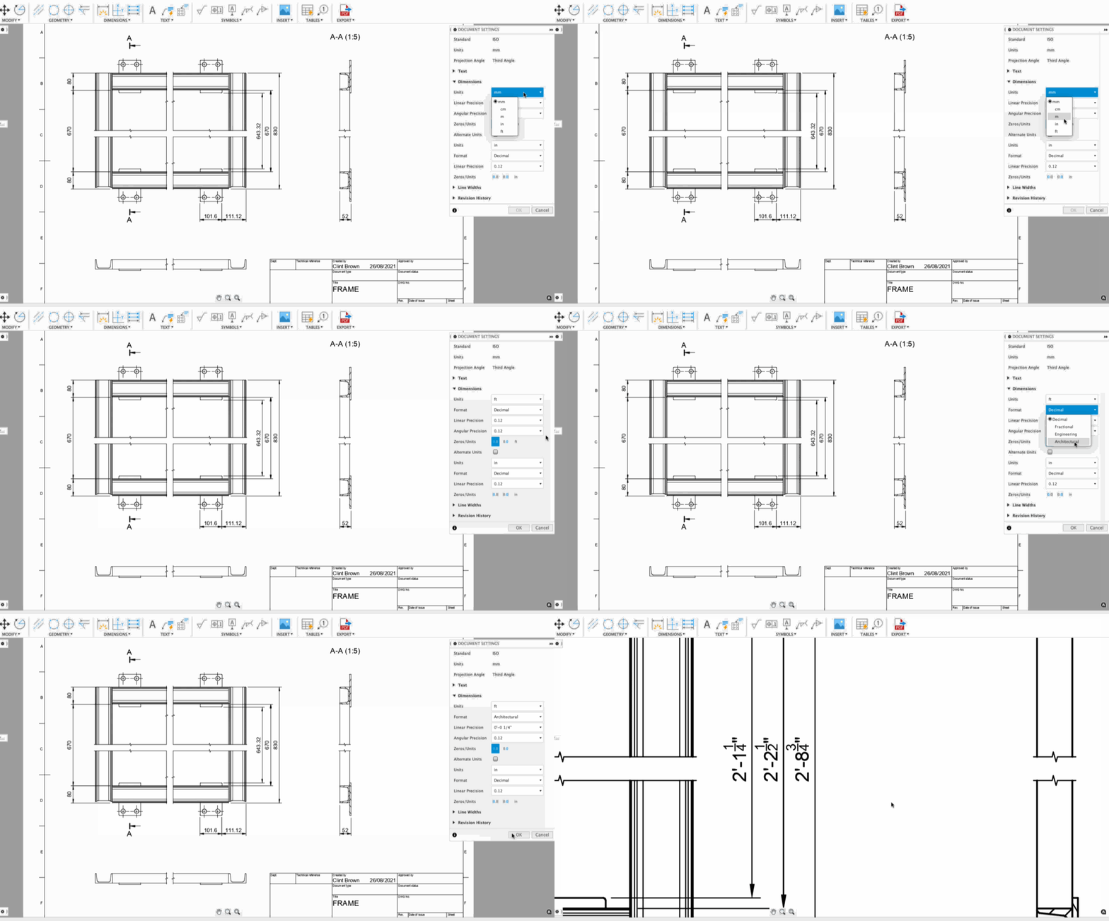
We’ve added meter, centimeter, and feet in the available list of dimension units, joining the ranks of inches and millimeters. If you choose inches or feet as your dimension units, you will also see additional options such as Format type (Decimal, Fractional, Engineering, or Architecture), Linear Precision, and Angular Precision. You’re also able to display your units as well as Alternate units for that extra flexibility.
Learn more about the Dimension units
Improved! Break Projected Views & Section Views
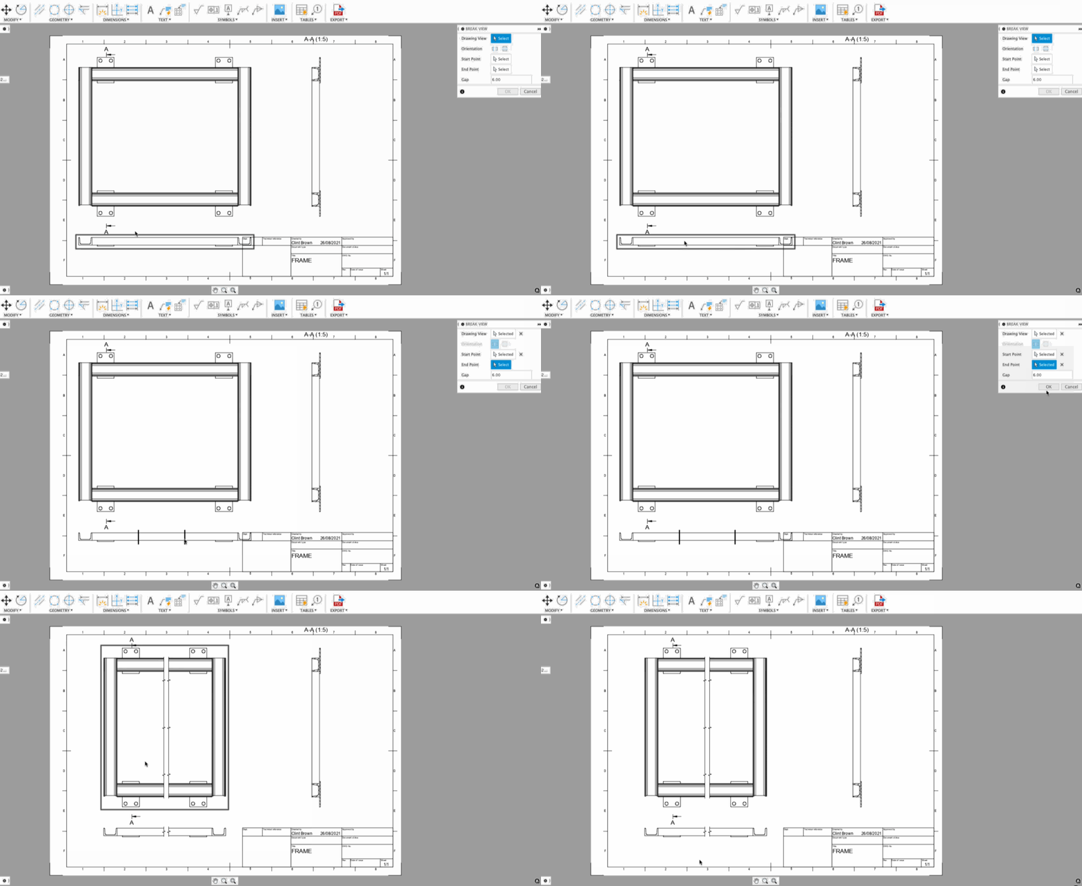
Previously, Break View only worked on Base Views. Now you can use Break View on Projected Views as well as Section Views. What’s even better is that adjusting the break on either view will also update the Base View, and vice versa. In essence, a change made anywhere is updated everywhere.
Learn more about the broken views
Improved!: Arrange Dimensions with Stack or Align Options
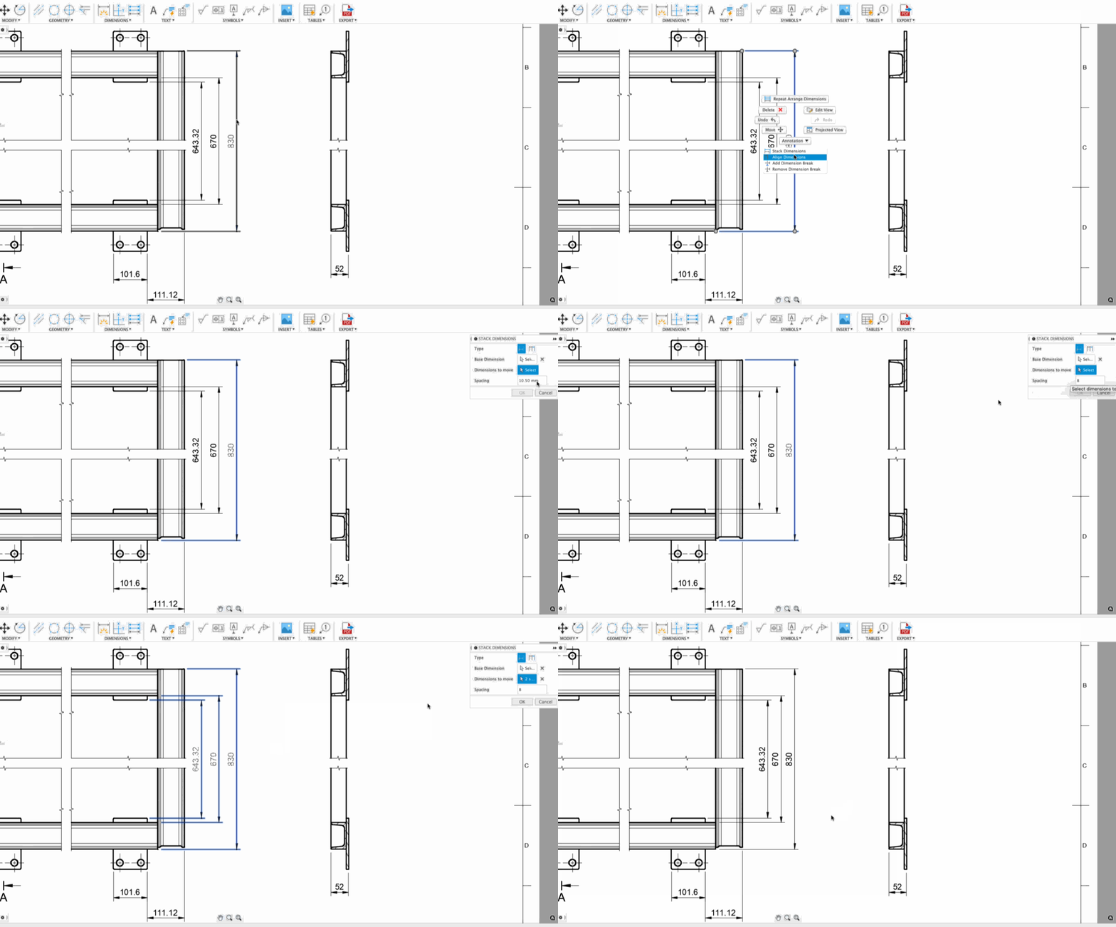
Now in the Arrange Dimensions tool, you have the option to stack your dimension with even spacing, as well as align them in a nice straight line. Here are a couple of examples of how Stacked and Aligned can help you better tidy up your drawing. You’ll also notice that they even work across views as well.
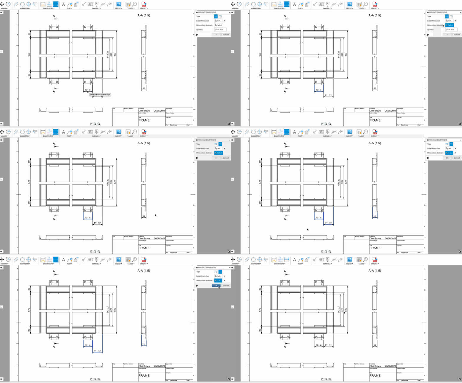
Learn more about arranging dimensions
New! Short link options for Flat Finishing

In the spirit of improving tool-path efficiency, you’ll now have Short link options for your Flat Finishing operations. This will give you more control over linking by letting you set the Maximum Stay-Down Distance, as well as the transition type to No Contact, Straight line, or Smooth.
New! Haas, Haimer, and IMCO Tools and Holders added

Under the tools tab in our cam.autodesk.com page, you’ll find new Haas holders, Haimer holders, as well as IMCO tools (Metric or Imperial) available for download.
New! Autodesk generic simulation files in Machine Library
The Machine Library lets you manage your machine tools by using Machine Configurations to define your available machines and resources. These configurations can automate the settings in your Job Setup. There are many Machine Configurations available in the standard library. In the library you will find the following new Autodesk generic simulation files for nutating milling machines kinematics:

In addition, you will have available configuration files for some of the leading machine manufacturers:
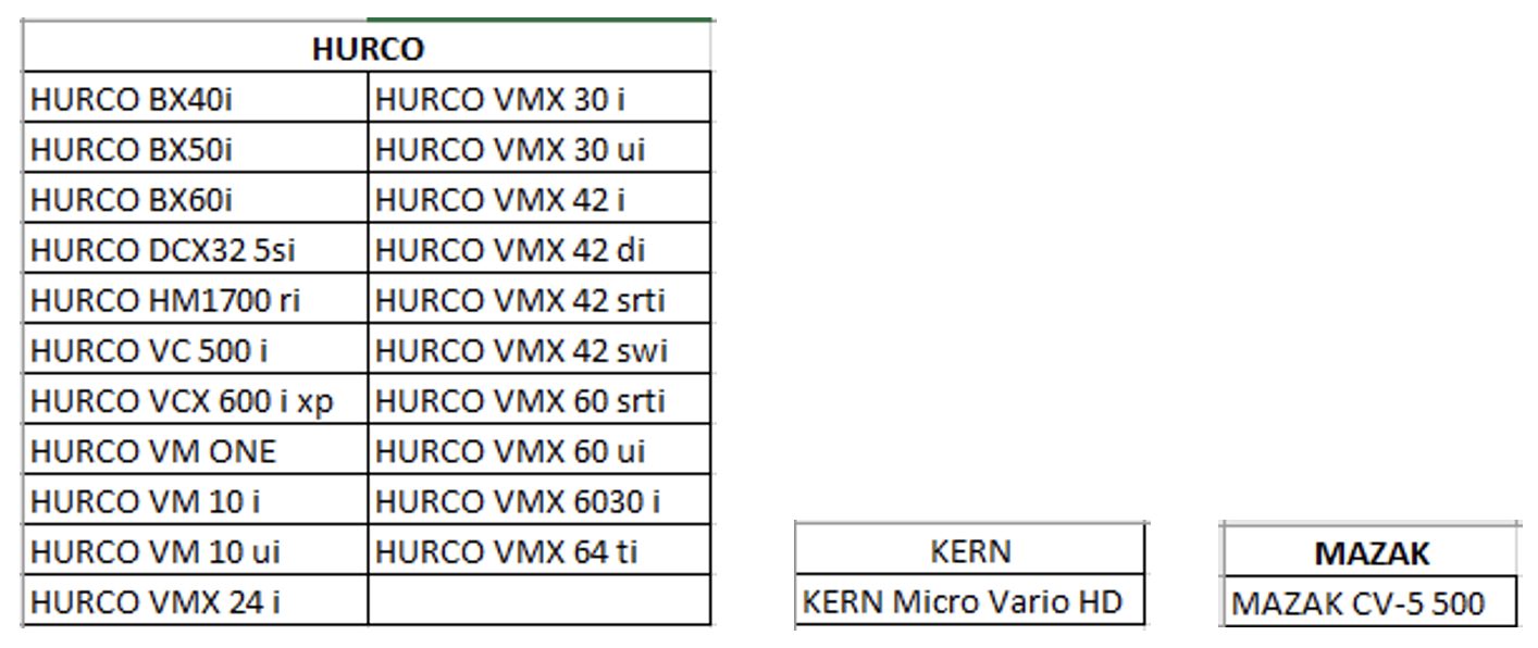
The easiest way to get started, is to copy an existing configuration that matches some of the characteristics of your machine.
Improved! Steep & Shallow – Optimized Perpendicular Passes

The Steep and Shallow strategy has a new option to output optimized perpendicular passes when using Parallel only (Set Threshold angle to 90 and shallow). When the cut direction of the tool runs parallel to a steep region, a inconstant step-over can occur, leading to greater cusp heights, greater tool loads and a poor quality surface finish. The new Optimized Perpendicular passes in Steep and Shallow maintains the step over regardless of the area. The autonomous nature of this new addition means it only applies the optimized passes where necessary. You’ll notice a more efficient toolpath that machines a more consistent surface finish.
Learn how to use Optimized Perpendicular Passes
YouTube Fusion 360 – How to use Steep & Shallow with ‘Optimized Perpendicular Passes’
Improved in Preview! Machine Animation for NC Programs and 2D cutter compensation

Currently still in Public Preview and free to try, we’ve improved our Machine Simulation capabilities to now be able to simulate NC programs before they are exported. You’ll also be able to see a machine simulation of the tool-paths with 2D cutter Compensation turned on. This expands on what can be simulated more realistically, allowing you to communicate more effectively to your clients. Keep in mind that this functionality currently does not support machine collisions, nor does it support simulations between tool-paths.
Improved! Wear and Inverse Wear Compensation options in Turning Profile Finishing
We’ve reintroduced Wear and Inverse wear options in the Compensation Type drop-down menu for Turning Profile Finishing. It’s another way for you to use compensation and improve part quality, while reducing scrap at the same time. G41 (Inverse-wear = Compensate the path + TNR left) and G42 (Wear = compensate the path + TNR Right) will tell the controller to get the nose radius value at the controller. You can change this value on the controller to account for the insert wearing.
Updated: Milling, Turning, and Turn-mill Post Processors
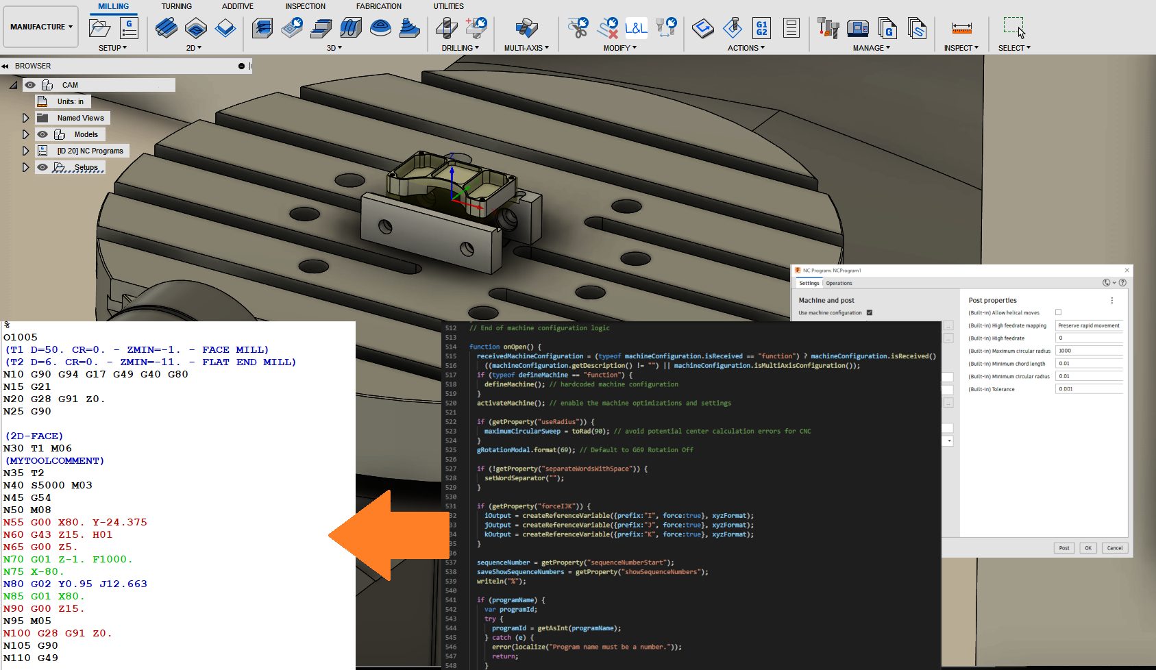
We are continually working hard to bring you updates and improvements to the many open-source Post Processors and Machines we offer for free. Expand the follow to see what’s new for Milling, Turning, and Turn-mill post processors. You can find the latest in our post processor offering on the Online Post Library where you can search by vendor, type, or name, and see any recent changes to each post processor.
[expand title=”Expand to see updates”]
Created a separate post processor for CR Onsrud with saw blade support.
Haas GM2-5AX gantry, Haas VR-8, Haas VR-9, Haas VR-11, Haas VR-14
Enhanced the smoothing (G187) control in the Haas GM-2 and VR-series post processors.
Haas next generation, Haas next generation inspect surface
Added property for rotary axes clamp code usage and forced rotary axes unlock codes for simultaneous toolpaths if property ‘useClampCodes’ is set to ‘No’;
Optimized the unwind of the rotary axes;
Fixed initial rotary axis position in polar interpolation mode
Tormach post processor will now select the closest solution for the rotary axis output and use a G92 to minimize rewinds.
Added circular moves for GCode format only.
Fanuc, Fanuc inspection, Haas next generation, Haas next generation inspection surface, Haas umc-750, Heidenhain, Heidenhain 426, Heidenhain inspection, Hurco, Makino D200Z, Makino D300, Makino D500, Makino Slim3n, Mazak, Siemens 840d, Siemens 840d inspection
Implemented inverse feed rates in post processors supporting machine configurations.
Output the correct spindle direction code for transfer operations.
Okuma turning, Okuma lb3000 mill-turn
Fixed stock-to-leave direction in turning canned rough cycle.
Output the correct spindle direction code for transfer operations.
Added an option to skip probing toolpaths, addded the property ‘Use G95 for tapping’.
Export CNC file to Visual Studio Code
Added post-processor to export CNC files to the Autodesk post-processor add-in in Visual Studio Code.
[/expand]
Improved! Height Offset option for Arrange

We’ve added a new optional parameter – Height Offset – that allows you to specify the Z height of where the objects are arranged. The default value is zero which places the objects directly on the selected plane, sketch, or face. You may use numeric values, expressions, or parameters as input.
Learn more about setting the Height Offset
Improved! Face Direction control for Arrange
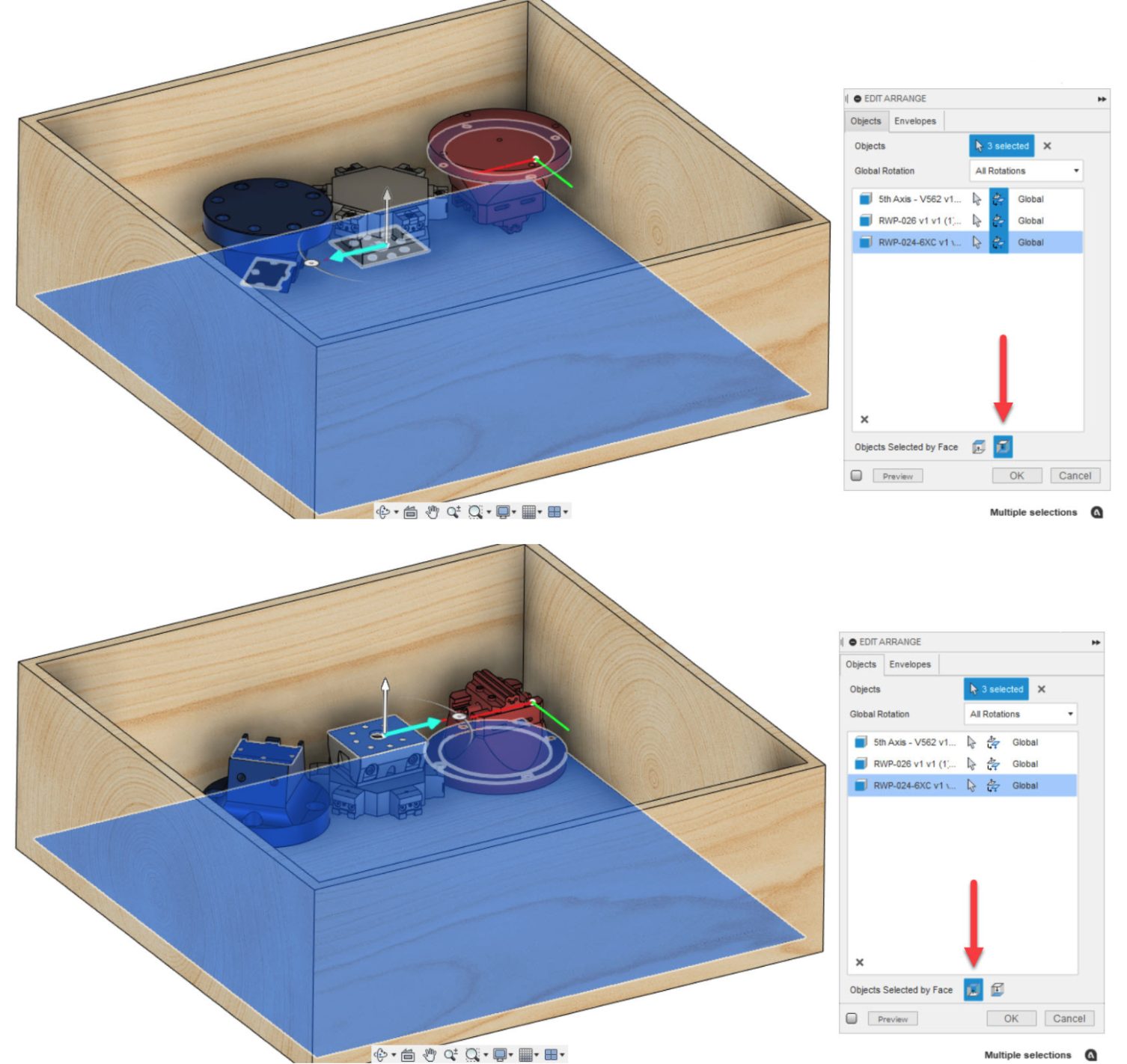
Previously, all objects selected using a planar face were positioned with the selected Face Up as the default orientation for Arrange. Once arranged, the component level Flip toggle allowed flipping as necessary. Now there’s an option to specify how the Objects Selected by Face are positioned – Face Up or Face Down – relative to the selected plane, sketch, or face. Additionally, each selected object in the list has an appropriate icon next to it to indicate whether it was selected as a component or an explicit planar face.
Learn more about Face Direction control
Improved in Preview! Advanced Arrange UI enhancement for Part Grain control and allowed Rotations
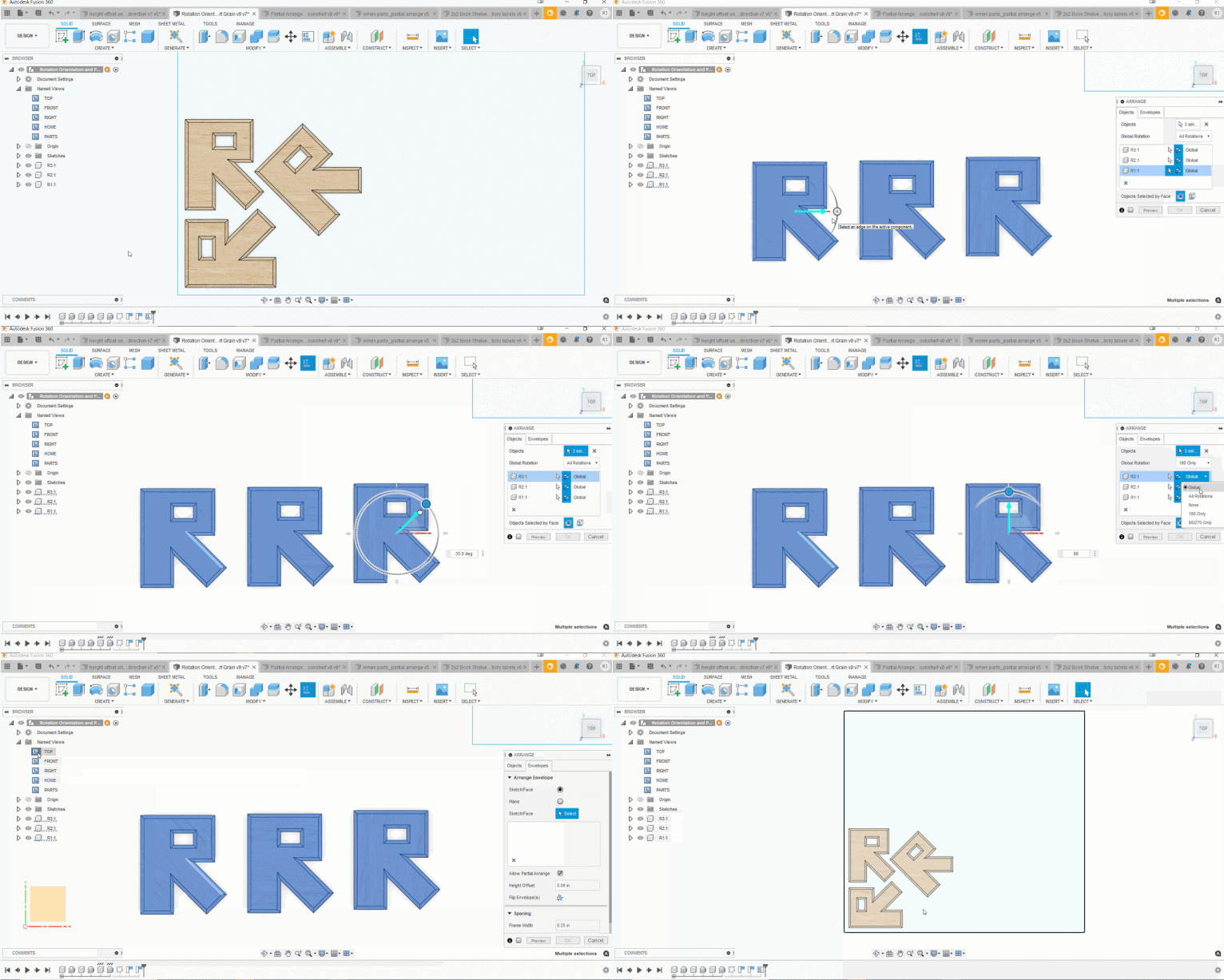
In the Advanced Arrange Preview, we’ve significantly reduced the number of clicks needed to specify part grain direction and the allowed rotations. You no longer need to uncheck three different boxes for each object that you don’t want to rotate. The arrange dialog now has a Global Rotation setting that automatically applies to all objects selected. We understand that a global setting may not work in all scenarios. To provide additional flexibility and control, there’s also a component-level override that allows you to set an explicit rotation allowance for the objects.
To ensure the arranged result considers the part grain direction, you must specify a grain for the individual parts and use the appropriate rotation allowance setting (None or 180 only). To set the part grain, you may rotate the handle to desired angle or simply enter a value. Upon arranging, the cyan arrow that represents the part grain will align parallel to the length direction of the envelope. Currently, it is not possible to adjust the grain direction for the envelope/sheet. This is coming soon.
Learn more about how to set Global Rotations
Improved in Preview! Allow Partial Arrange option for Advanced Arrange
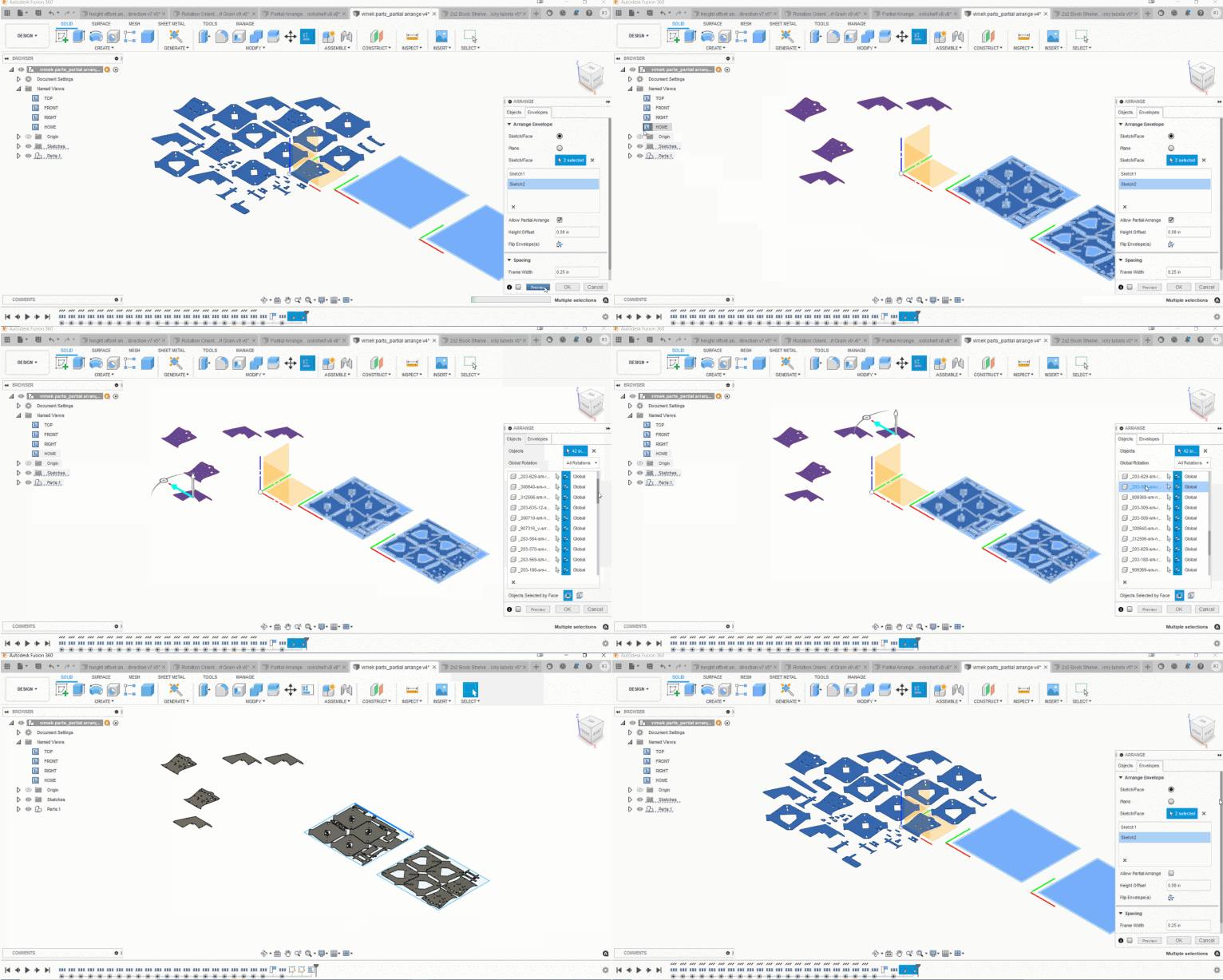
Until now, Arrange would return an error if it was unable to fit all selected objects in the specified area. The error would prompt you to either reduce the number of objects selected or increase the envelope area. This often required several attempts to dial it in correctly. Based on your feedback, we’ve added a new option to Allow Partial Arrange. When enabled, it will produce a successful arrangement with as many objects as it can fit within the available area. All un-arranged components are highlighted in the list and are left at their original location in the canvas. The beauty of this enhancement is in the way it handles the unarranged components. Unless explicitly deleted, they are maintained in the objects list. This preserves the original intent and highlights the true power of its parametric nature by allowing the arrange feature to update dynamically as the part design and/or envelope size is modified.
New! New Setup from G-Code
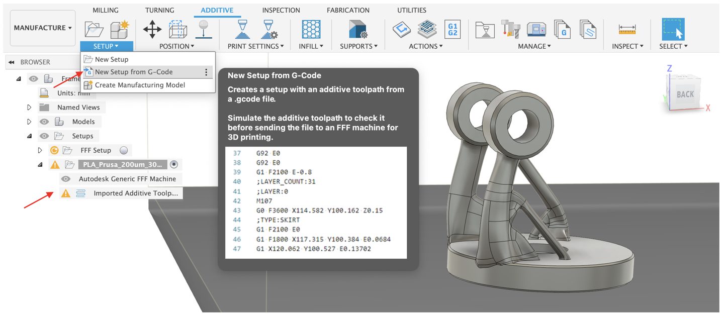
Good news! You can now import G-Code into Fusion 360 for your additive manufacturing needs. Under the Setup panel drop-down menu, you’ll find “New Setup from G-Code”. Imported G-Code can also be verified and simulated just like native toolpaths created in Fusion 360. This gives you the flexibility to use G-Code created in other tools as well as the assurance to make sure they work properly with Fusion 360’s verification and simulation capabilities.
Learn more about creating an additive setup by importing G-code
New! SLM: New Metal 3D printers and print settings from Aconity3D

Improved! Print using duplication mode or mirror mode on all the BCN3D printers

We can now print using duplication mode or mirror mode on all the BCN3D printers we support by choosing the printers / post combination named “duplication” or mirror”.
Check out this video to see this workflow in action:
Updated: Additive Post Processors

[expand title=”Expand to see updates”]
Added temperature tower feature to all additive post processors.
[/expand]
New in Preview! FEA Mesh added to Additive Manufacturing Process Simulation

For those of you trying the Additive Simulation Extension Preview Functionality (From your Extension Manager), we’ve added FEA Mesh as a pre-check option.
Improved! Learning content for the Additive Simulation Extension

We’ve enhanced the learning content available in the online help for the Additive Simulation Extension. The extension enables process simulation, which you can use to predict the displacement of parts during the additive manufacturing process.
New! Support 3mf export in the Fusion API
Check out the latest API help documentation for a more detailed what’s new.
Add-in Spotlight: Bommer and building part lists
Our partners at Bommer have also been hard at work too, adding features to let you build part lists that include any Bommer custom properties and any selection of rows from your design. They wrote a nice blog post about this functionality in more detail a couple months back, Read more about it here: https://links.getbommer.com/blog-fusion-360-drawings-custom-part-lists.
To see details around this, our extended list of fixes, as well as known issues, check out this forum thread in our support forum.
V.2.0.10940
Improved! Export to ODB++ for Electronics Design
Important fixes:
Fixed: Data panel put you in the wrong project on launch
david.quayle told us that when he launches Fusion 360 and opens the data panel, Fusion 360 places him in the wrong project, and not the one from the previous session. Sorry about that, this is now fixed and the data panel will remember which project was last accessed.
Fixed: High CPU usage on certain designs on open
Some of you have been experiencing usually high CPU usage when you opened certain designs. We found the bug that was clogging up the tubes and we flushed it out. This is now fixed.
Fixed: Mesh position changed when re-computing the design
This was another issue that was bugging the heck out of us (no pun intended), but we quickly got it sorted and now your mesh position shouldn’t change unexpectedly when you do a Compute All.
Fixed: Crash in pattern instance control workflow
We fixed an issue where if you deleted the setup(or the pattern) of a particular model and double clicked/edited on the existed NC program which was associated with the deleted setup, Fusion 360 became unresponsive.
Fixed: Selection Visibility dependent on Design Space model visibility
Seth Madore told us that if the visibility of the model(s) is/are turned off in the Design workspace, but active and visible in the Manufacture Space, no faces can be highlighted to indicate that they have been selected. One must then go into Design Space, turn the model on and then go back to MFG space. This definitely felt odd to us, so we dug into and found a bug that was causing this issue to happen. Now it is fixed.
Fixed: Spacemouse 4.0 – 3DConnexion I3DN not working
We recently discovered that I3DN was not working anymore. The center of rotation was not set correctly. Instead, it was set in a fixed position, yet the 3DMouse has its own rotation point. Changing the center of rotation for the 2D Mouse (Shift + MMB) does not affect the center of rotation of the 3DMouse. This is now fixed and I3DN should work again.
Fusion 360 Insider Program
Become a Fusion 360 Insider and get early access to what’s new
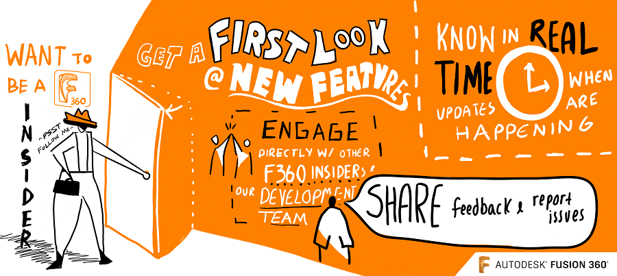
Apply to join and get exclusive early access to next production version of Fusion 360, two weeks before it is released to the everyone else. Along with getting early access, you will also be able to:
Get your hands on new features, before everyone else
You’ll be the first to get what’s coming in next product update: new tech, improvements, and fixes.
Know in real-time when updates are happening, what’s new, and what’s coming
Know, in real-time, when we are deploying an update and what’s coming in the next one, straight from the development team.
Gain exclusive access to the Insiders Lounge and report issues
As a member, you’ll have access to our private Insider Lounge, where you can engage with other Insiders, Autodeskers, and report bugs and issues directly within the same space.
One thing we do want to be clear about: this is not a beta program. This is early access to the next production update release by installing and running a pre-production build. If you are a content creator, add-in developer, power-user, or just someone who wants to stay ahead of the curve and test new workflows, this is a great opportunity for you to be a part of something special. To join this program, simply apply by filling out the application form along with an NDA. Once your application is approved, you’ll be able to access the virtual Fusion 360 Insider Lounge, install the pre-production build and start testing out the newest features!
By clicking subscribe, I agree to receive the Fusion newsletter and acknowledge the Autodesk Privacy Statement.
Success!
May we collect and use your data?
Learn more about the Third Party Services we use and our Privacy Statement.May we collect and use your data to tailor your experience?
Explore the benefits of a customized experience by managing your privacy settings for this site or visit our Privacy Statement to learn more about your options.