V.2.0.14337
We got reports of you not being able to upload non-native Fusion 360 designs to your Data Panel. This hotfix addressed this issue.
V.2.0.14336
- We fixed a crash caused by a timing issue.
V.2.0.14335
Modeling
- Previously, it was possible to create an edge with the ‘Insert Point’ command across multiple faces, as shown in Giichi Endo’s YouTube video.
However, in the recent update, this behavior did not occur and edges could not be created after selected points on edges. This is now fixed. - We fixed a crash issue that was happening when you were trying to edit a pattern.
- We fixed a crash issue that was occurring when pressing the V key and when dragging a construction plane edge at the same time.
- We fixed an issue where if you inserted an edge on an open T-Spline body, selected an edge on the open side, dragged the offset to 0 and then clicked OK, Fusion 360 would crash.
- As reported by fahef77309 in this thread, there was a weird instance where Numerical Inputs where unavailable to you in the Insert Mesh dialog. Sorry about that – this bug is now fixed.
Electronics
- We fixed an issue where clicking on the ERC banner saying “Fusion 360…Undo.cpp,Line 457” after committing a Replace action caused Fusion 360 to crash on macOS.
- For certain designs, tStop was not transferred to 3D PCB and the soldermask was on the entire 3D PCB model. This is now fixed.
- We fixed a bug that was causing Fusion 360 to crash when you tried to undo Synchronize on certain designs.
- We fixed another bug where Fusion 360 crashed when you tried to undo route after renaming net class.
Manufacture
- We’ve improved how expressions are handled when you’re entering them in the Compare and Edit dialog. Previously bad expressions were being accepted and committed without any verification on Fusion 360’s part. Now if you enter a bad expression, Fusion 360 will flag it and will prevent you from committing it.
- We fixed in an issue in the kernel that was causing wrong ordering in 2D Contour, 2D Pocket, and 3D pocket. It is now always inside -> out by default.
- We added a new API class CAMHoleRecognition which contains most, but not all, of the same functions as CAMFolder.
- Based on this thread engineguy and jezek.jaroslav were involved in, we fixed possible missing offsets in Pocket2D and Contour2D strategies when input contours contain arcs.
- We fixed an issue in Metal powder-bed printing where the last segment was missing in closed loops of open supports, e.g., when “single hatch tube” supports were used.
- When removing a machine (that supports extended WCS) and reselecting it back into the Setup, any invalid custom WCS will be set back to default. However, if you entered an invalid value, but then changed the format twice, some strange behavior would occur. This issue is now fixed.
- We fixed a crash issue where typing text in the WCS for Machine WCS in the Setup dialog caused it be highlighted in red, but if you changed the format, Fusion 360 would crash.
API
- We fixed an issue where the controlPoints property of SketchControlPointSpline was failing. We fixed this by telling the controlPoints property to return null instead of failing.
- A change in behavior of the Sketch.project method has been reported on the forum. It’s breaking some existing add-ins.
- The problem is the result is no longer linked to the entities that were projected. This is different from the previous behavior. The code below and the attached f3d can be used to reproduce the problem. After running it, you’ll see no relationship between the curves in the two sketches. It should be that if you edit any of the curves in the sketch named “Source”, the curves in “Target” update to match. And you shouldn’t be able to edit any of the curves in “Target”. The test code has a switch to test with a single entity or multiple entities, and both exhibit the problem.
def run(context):
try:
app = adsk.core.Application.get()
ui: adsk.core.UserInterface = app.userInterface
des: adsk.fusion.Design = app.activeProduct
root = des.rootComponent
sourceSketch = root.sketches.itemByName(‘Source’)
targetSketch = root.sketches.itemByName(‘Target’)
projectAll = True
if projectAll:
curves = adsk.core.ObjectCollection.create()
for curve in sourceSketch.sketchCurves:
curves.add(curve)
else:
curves = sourceSketch.sketchCurves.item(0)
targetSketch.project(curves)
except:
ui.messageBox(‘Failed:\n{}’.format(traceback.format_exc()))
As of this update, Sketch.project creates linked results as it should.
See fixes for the previous versions:
V.2.0.14104
Modeling
Volumetric Lattice now officially available in the Product Design Extension
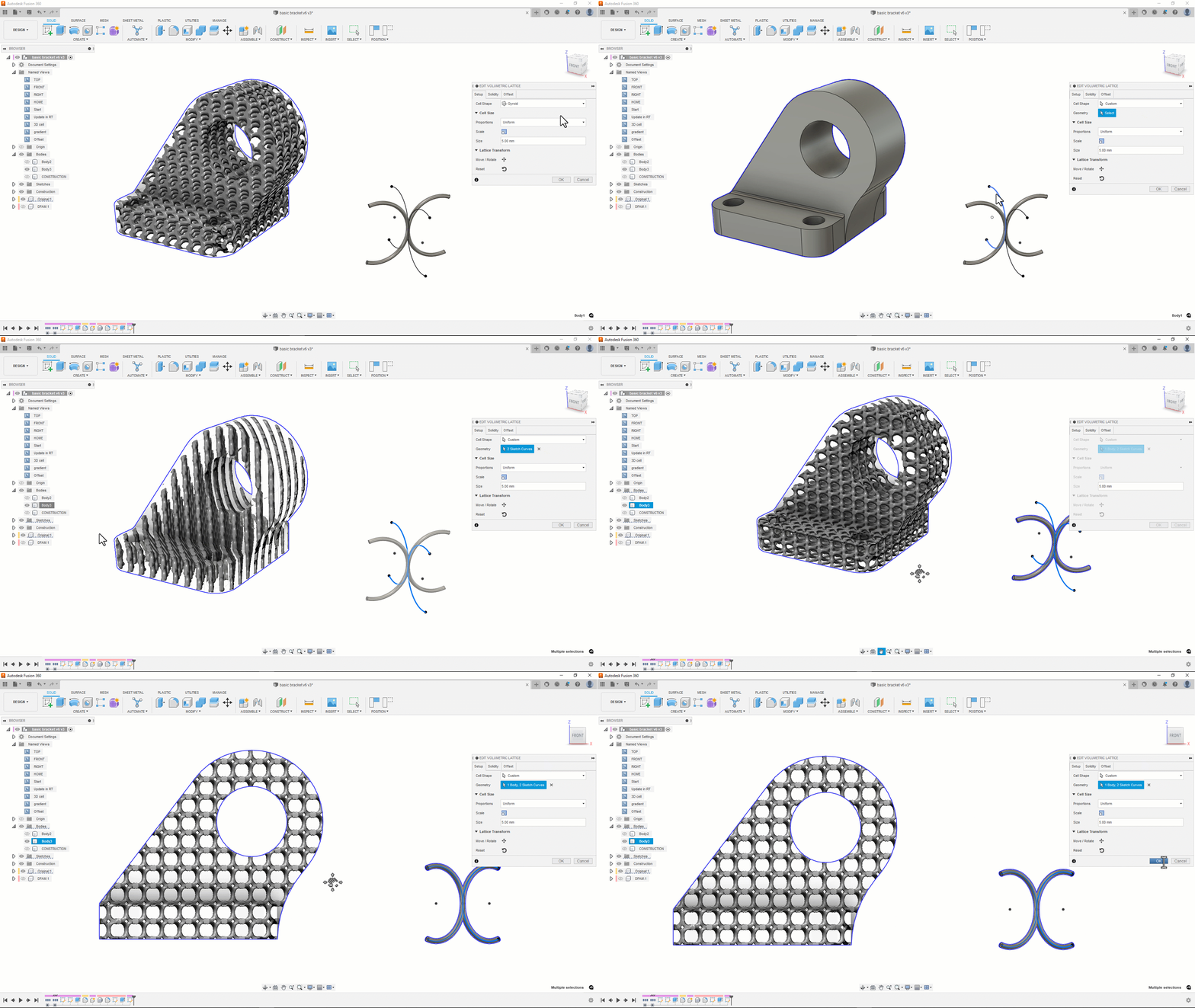
In January we added a new functionality called Volumetric Latticing into the Product Design Extension as a preview. Volumetric Lattice supports easy ways to create lattice structures for parts being design specifically for additive manufacturing technologies.
With the September release, Volumetric Lattice will no longer be a preview feature; instead it is now a fully integrated solution in our Product Design Extension. We updated the tool with several new lattice cell types and the option to define custom cell structures by using design tools in Fusion 360.
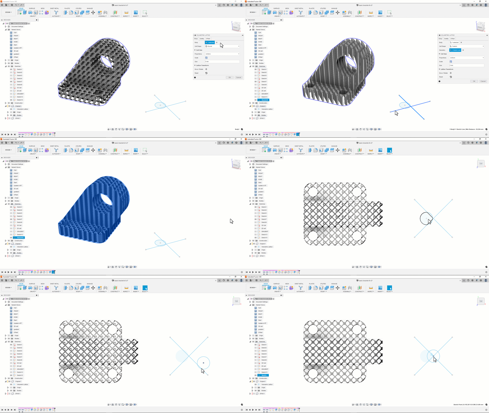
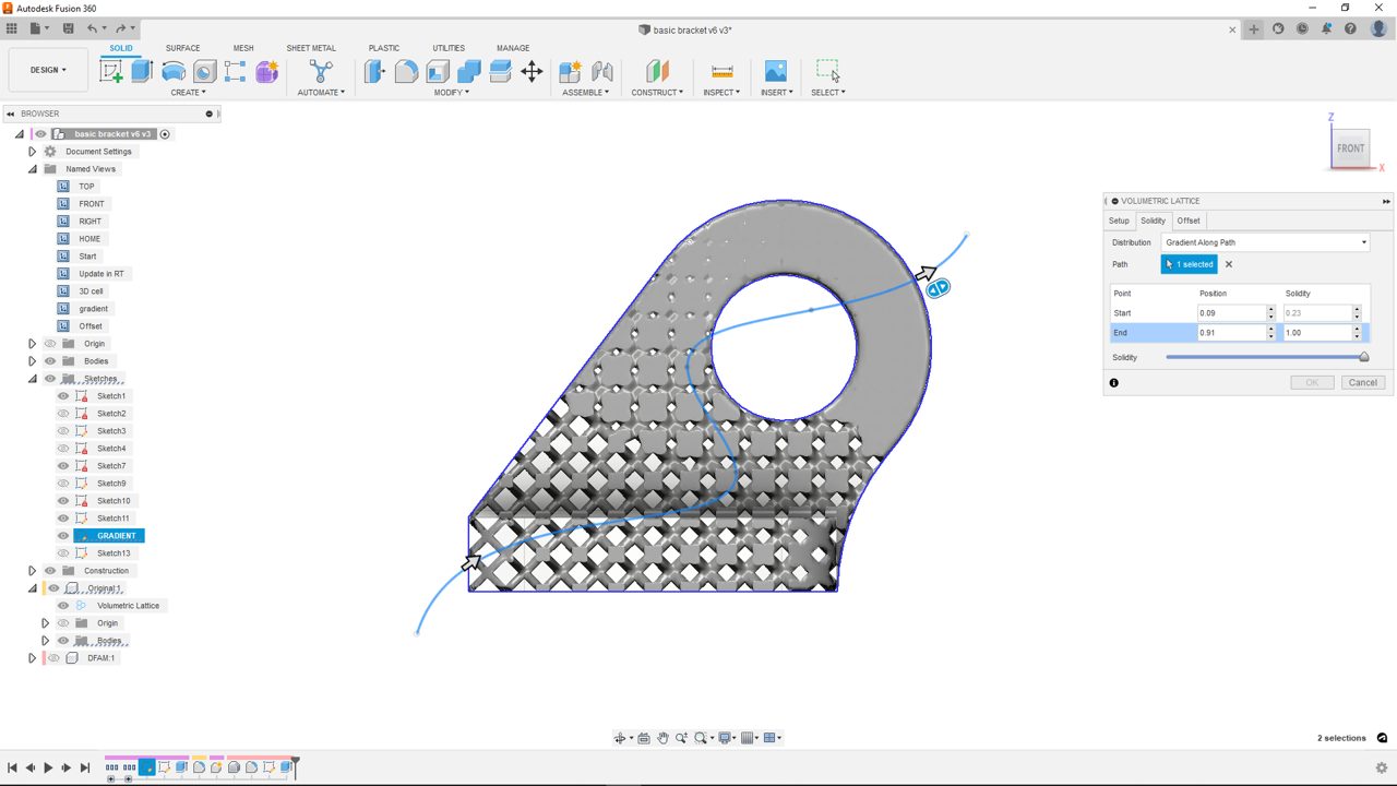
With in-scene manipulators and gradients being defined along paths it is possible to upgrade your design in an intuitive way.
It is now also possible to directly add your part to an additive manufacturing setup without creating a mesh before, this prevents data loss and improves your overall performance in comprehensive projects.
Resolve External Components now officially available
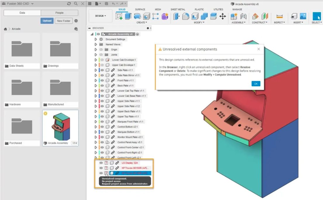
If you’ve ever tried to open a design in Fusion 360, but couldn’t because it contains missing external components, this feature is for you. Back in January, we added the Resolve External Components preview to let you open assemblies with unresolved external components and attempt to resolve them.
As this comes out of preview, any time you try to open a design with unresolved external components, you’ll see a notification and then you can open it. In the Browser, right-click an unresolved component, then select Resolve Component or Delete.
In addition to inserted components, we now also handle:
- Derive sources that are directly missing
- Derive sources that contain unresolved external components
External components will become unresolved when a design or its project is archived or deleted, and may appear unresolved for certain people due to permission restrictions.
If a design is missing because it’s deleted, it will be missing for everyone. However, it’s important to note that if a design is missing because you don’t have access to the project where it’s located, it may be available for other project members. In this case, we recommend that you work to gain access to resolve external components before you make any significant changes to the design.
If you really do need to make any significant changes to a design in this state before you resolve the components, you’ll need to use the new Modify > Compute Unresolved command first, which will compute only the features related to unresolved external components in the assembly. You can run Compute Unresolved manually to see the outcome or Fusion 360 will automatically invoke it when you first edit the design to ensure you are working on the latest computed state.
We recommend that you resolve missing components as soon as you encounter them. They are not expected to be maintained over the long term and you should address them as general design maintenance.
Learn how to resolve external components in an assembly.
New Pattern Type option
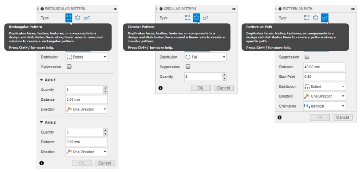
We’ve added a new Type option in the following Pattern tools, to make it easier to switch between: Rectangular Pattern, Circular Pattern, and Pattern On Path. Regardless of which pattern command you started with, you can toggle between the 3 types right within the command dialog, without needing to go digging within the toolbar drop-down menu.
Learn more about the Pattern tools.
New Seed And Boundary option in Selection Tools

You can now use the Seed And Boundary selection tool in the Design workspace, where it used to only be available in Simulation and Generative Design. Use it if you need to select a series of faces on a complex body, for example one with many small details like ribs, webs, holes, or fillets.
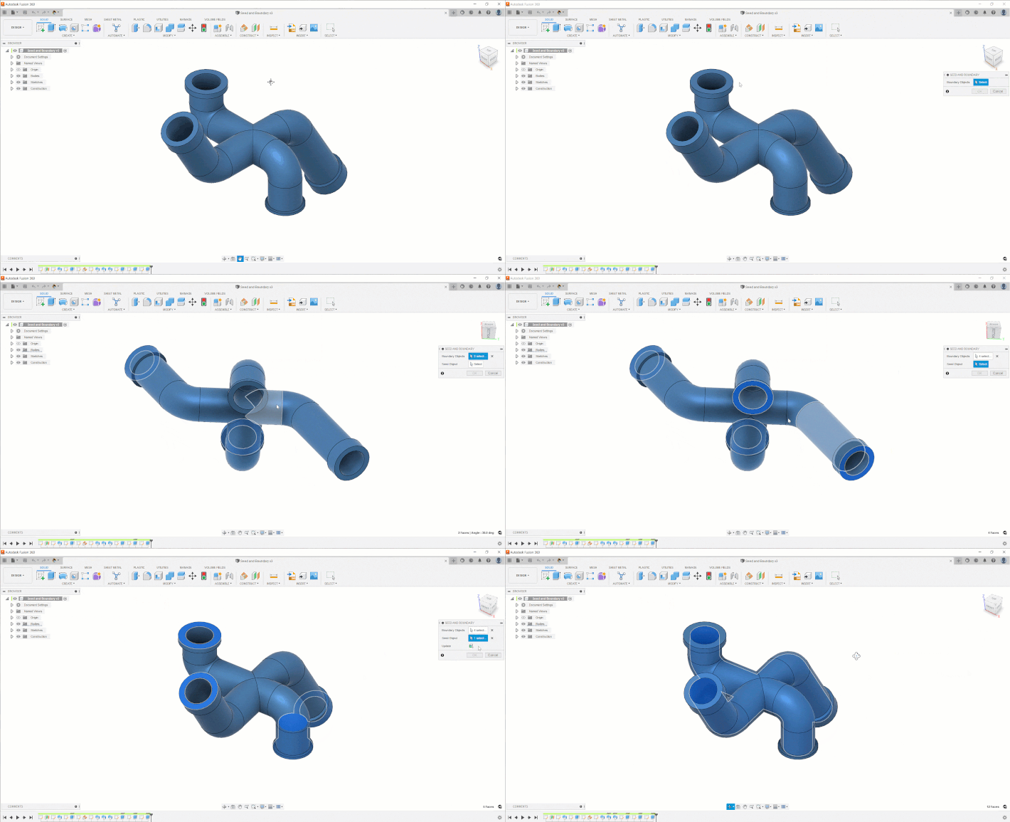
Learn how to use Seed And Boundary selection.
New Project Axis option in Revolve tool
We’ve added a new Project Axis option to the solid and surface Revolve tools. It’s checked by default, and projects the Axis you select to the plane of the selected profile that you’re revolving. Uncheck to use the axis in place, without projecting it.
New Flip option in Section Analysis tool
We’ve added a new Flip option in the Section Analysis tool, to make it easier flip the section over the cut plane.
Learn how to use Section Analysis.
New “Remove T Points” option in Form > Utilities > Make Uniform tool
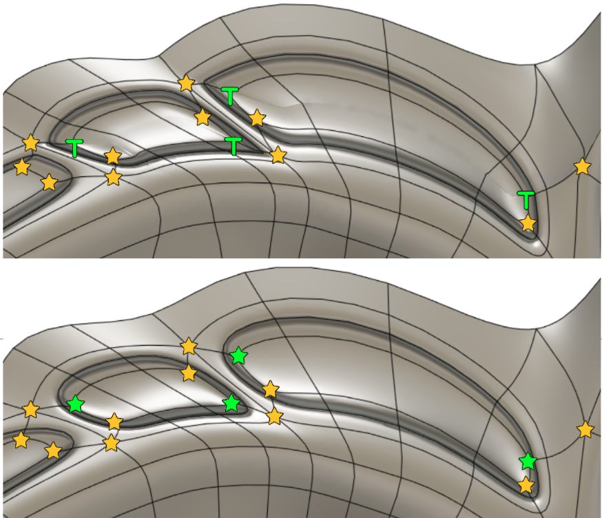
In the Form contextual environment, we‘ve added a new option to the Utilities > Make Uniform tool to remove T-Points.
When you check the new Remove T Points option, all T-points on the selected T-Spline form body will be converted to star or cap points. You can use this option as a repair tool when T-points cause undesirable surface quality or conversion from T-Spline form body to solid or surface body fails as shown in this user forum post.
Learn how to use Make Uniform.
Better solid and surface face layout when converting T-Spline form bodies
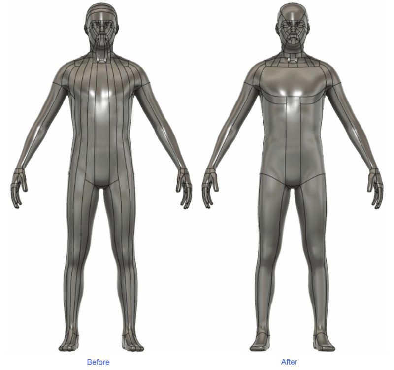
In the past, when you converted a T-Spline form body to a solid or surface body, you often encountered long, narrow faces, which were hard to edit (above: left image). We now avoid long, narrow faces and reduce the overall number of faces (above: right image).
Open T-Spline (TSS or TSM) files
You can now import subdivision bodies exported from Alias (File > Export > Active as Subdiv > TSS). Use either of the following methods to import TSS or TSM files into Fusion 360:
- File > Open > Open from my computer
- Form contextual environment > Insert > Insert T-Spline
TSS (T-Spline Surface Scene) is a binary file that contains one or more T-Spline form bodies. TSM (T–Spline Mesh) is a text file that contains a single T-Spline form body.
Learn how to insert T-Spline files into a design.
Design Performance
Performance just got better; with this update opening design files will now happen up to 1.5x faster, Joint performance will be to 1.4x faster, and Windows Unselect performance will be up to 57% faster. Not only that, but now zooming in and out of complex 3D scanned mesh files should also feel much quicker and more responsive.
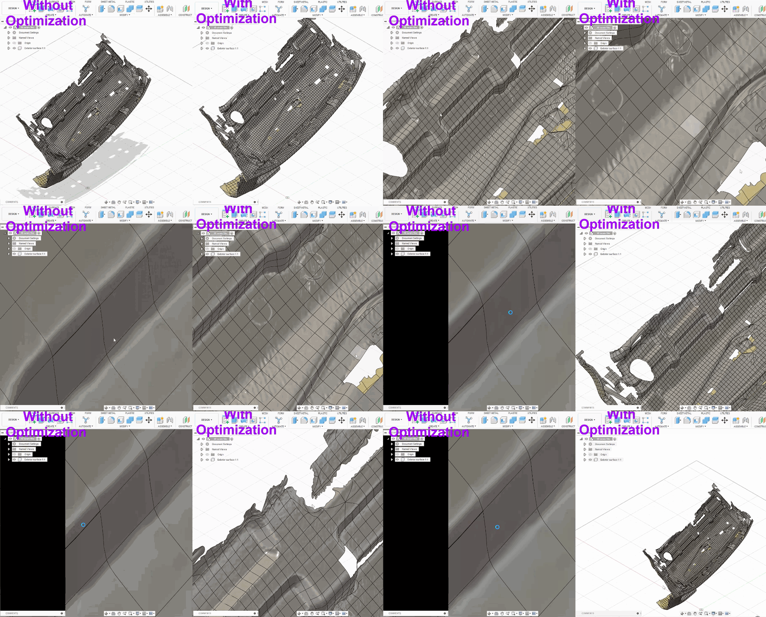
Modeling & Modify also have seen a significant performance boost with this September update. Here is a summary of what got improved:
- Improved Loft preview performance for Pan, Rotate and Zoom operations.
- Improved Pattern command input selection performance where invoking Pattern command and then hovering mouse over the component geometry in canvas makes Fusion unresponsive.
- Improved Move performance up to 2.2x faster.
- Improved Align command preview performance where hovering face or selection of body was taking time.
- Improved Compute All performance of up to 1.6x faster.
- Speed up Capture Design History performance up to 10.8x faster.
- Improved Timeline Move to End and Begin performance about 15%–81% faster.
- Improved turn on Component Visibility to be up to 32x faster.
Generative Design
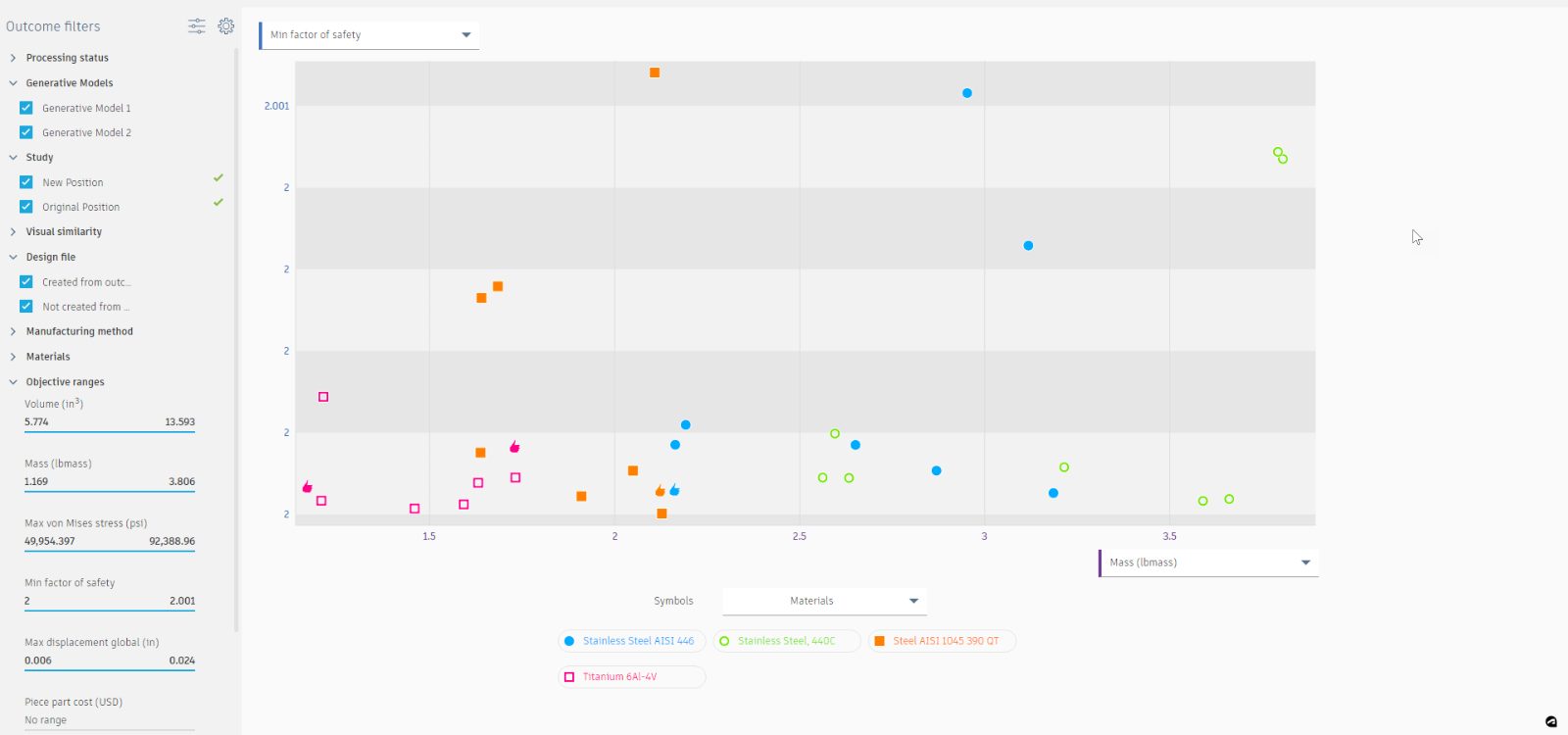
Improved Scatter Plot View in Explore
The Scatter Plot View has received a new color palette and iconography that will make outcomes more distinguishable from one another and more friendly to those of you who are color-blind.
Updated aPriori Costing Libraries for Structural Component Studies
In this update, we have refreshed our costing libraries from aPriori. This should make pricing estimates more accurate based on updated market conditions. There have been no changes to the supported materials, so everything should work just like it always has.
Improved Pre-check Performance for Structural Component Studies
If you have been working with setups with complex preserve and obstacle definitions, you have probably noticed some sluggish performance when hiding and showing geometry, creating and editing loads and constraints, and submitting solves. This is related to our interference pre-check that ensures obstacles don’t interfere with preserves and inadvertently remove loads or constraints during solve. We found a better way to manage these pre-checks and you should see snappier performance when working with these types of setups.
Boundary Condition Simplification in Fluid Path Study
Continuing with our efforts to simplify and add clarity to the setup workflows in the Fluid Path study, we have replaced the Inlet/Outlet command with 3 new commands with distinct intentions.
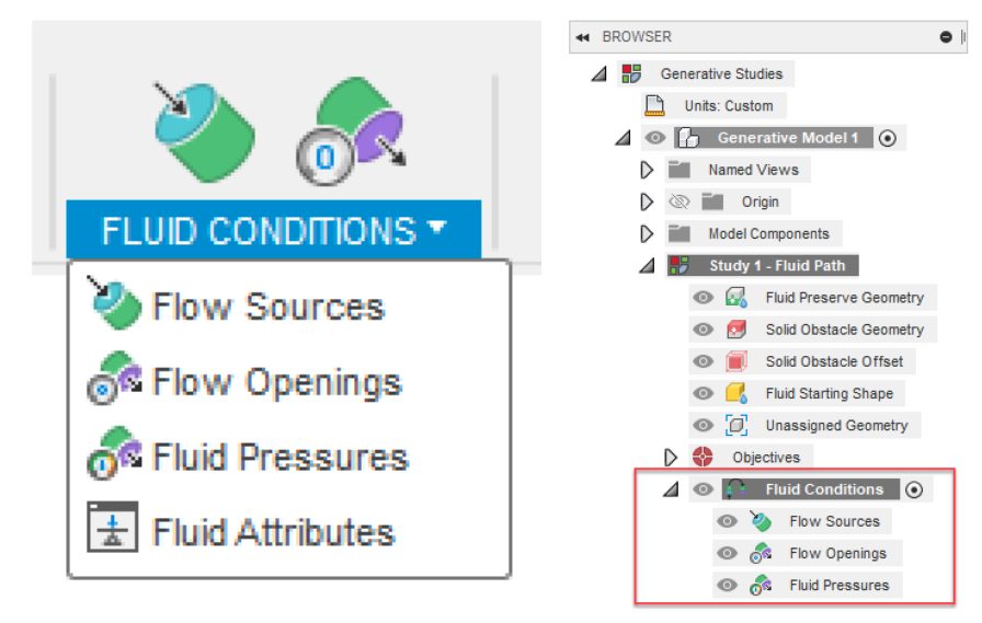
The Flow Source Command will now be used to define volume flow rates or velocities. Flow source boundary conditions should be used where both the magnitude of the flow and the direction of the flow are known.

We have added a new, Flow Opening boundary condition that should be used for areas in the setup where the flow domain is open to the atmosphere or is measured at a zero-gage pressure.

If areas in the setup have a known gage pressure reading, those areas should be defined with a Fluid Pressure boundary condition.

While both Flow Openings and Fluid Pressures have defined pressure values, the magnitude and direction of the flow is free to be calculated by the solver based on the generated shape. As a helpful tip, Fluid Path studies can be set up with the following boundary condition combinations.
- Flow Source(s) + Flow Opening(s)
- Flow Source(s) + Fluid Pressure(s)
- Flow Source(s) + Flow Opening(s) + Fluid Pressure(s)
Learn more here.
Improved Result Quality in Fluid Path Study
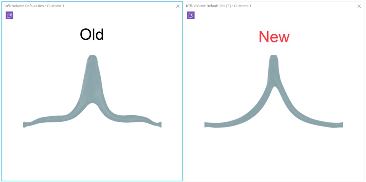
In addition to our workflow improvements, we have also been hard at work on our solver technologies. In this update, we have made significant improvements to the shape quality near preserve bodies with multiple Flow Opening or Fluid Pressure boundary conditions. If you have experimented with setups like this in the past and noticed a “necking” down before the preserve, give this update a try and you should see better results.
Electronics
Improved display of Meander status
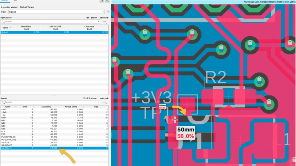
Meanders are used for directionally related signals, commonly used for USB connectors. Meandering will help get differential pairs D+ and D- to arrive simultaneously at both devices on the wire. Another common use for meandering is for RAM buses, since data lines must arrive at the chip at the same time with no delays. For this latest update, you will notice that the Fusion 360 meander command interface was improved to display the percentage to the target length and dynamically show you the trace length in the device manager.
Learn how to Add a meander to a differential pair.
Group Route Spacing Keyboard Shortcuts

Before you begin routing, check your Design Rules for the manufacturability of your PCB. The simplified DRC interface Fusion 360 makes this usually complicated task a straightforward one. Remember, most manufacturers offer their DRC preferences in an EAGLE and Fusion 360 DRU file that can be loaded in the DRC dialog box. The time-saving action of group routing allows you to select a group of signals and route them simultaneously.
With this new update, you will be able to control spacing with the new keyboard shortcuts: Key: 1 Action: Decrease Spacing | Key: 2 Action: Increase Spacing | Key: 3 Action: Minimize Spacing | Key: 4 Action: Swap Ends
Learn how to Assign Electronics keyboard shortcuts.
Flat Cap Lines

This feature has been requested for a while now and once again our team of developers have delivered. You no longer have to end your lines with an arc or a polygon to have a flat end cap trace. This new option is accessible in the line dialog box. The next time you are drawing a meander inverted F-Antenna on your PCB or want to avoid stubs on a line, make sure that you enable the Flat Line Cap that is now conveniently available in the dialog box.
New PCB configure in 3D model workspace
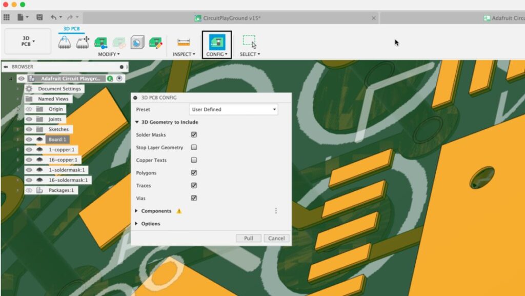
If you have been using Fusion 360 electronics you likely have been using the associative 3D PCB model as a vital tool to ensure your design is a success. The capability of fine-tuning PCB component placement directly on the mechanical workspace is integral to ensuring your PCB is completed collision free and with fewer re-spins. Previously, adopting changes between the PCB and the 3D model required a few synchronization steps. With the new 3D PCB Config option, you no longer waste time switching tabs to complete synchronization.
Layer Stack Up Thickness

An accurate 3D model representation of a designed 2D PCB is important in achieving a successful design. Before today, the layer stack-up thickness was not accurately represented in the 3D model, this has now been fixed. The 2D PCB layer stack-up total thickness is now reflected in the 3D PCB model, bringing the 2D and 3D views of your designed PCB closer together.
EAGLE Color Scheme now set as default

And for those of you who are migrating your projects from EAGLE to Fusion 360, in this update, you can reset your color scheme to match the EAGLE default settings in the Fusion 360 electronic preferences. All brand-new installs default to the EAGLE pallet, don’t worry if you have an existing installation; it remains unchanged. This will keep you in a familiar design environment when migrating to Fusion 360.
Learn how to Set your Electronics Preferences.
Simulation
Improvements to Job Status dialog
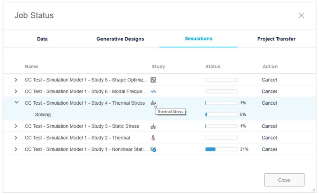
The Job Status dialog in Simulation and Generative Design now has new column for the Study type and we had enhanced the progress bar in the dialog to now show the % progress done on the solve.
Improved results loading experience for Injection Molding Simulation
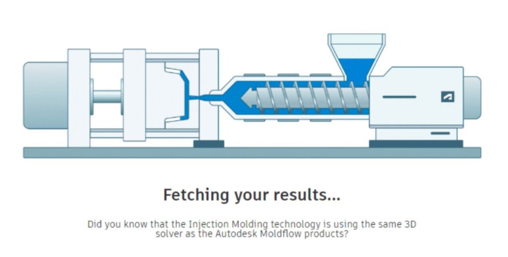
The results loading experience for Injection Molding Simulation now features some quick facts about Injection Molding for you to read as you wait for your results to load for visualization.
Study solvers have been moved to the cloud
As of this update, Fusion’s solver capabilities for Linear Static Stress, Modal, Thermal, and Thermal Stress will move to the cloud in September to improve performance and device flexibility. Linear Static Stress via the cloud is still included in your subscription at no extra cost. To learn more about why we made this change, check out our recent blog post.
If Modal, Thermal, and Thermal Stress is critical for you and this change will be a blocker for you, reach out to us at Fusion360SIM@autodesk.com and we’ll figure out a solution together.
Learn more about why we moved simulation to the cloud.
Drawing
New! Open model from Drawing View
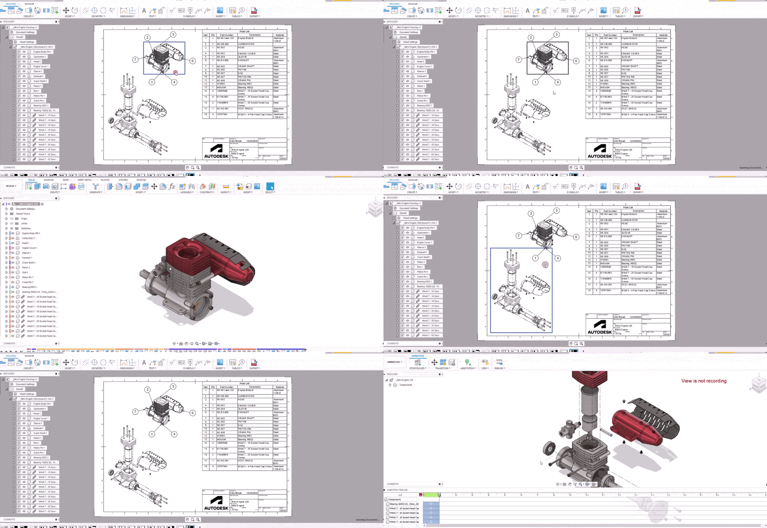
When working on a drawing, it was difficult to find & open the design if tweaks were needed. Previously, you had to find the correct browser node to open the design, with the September release, once a view is selected, right clicking on the view will allow you to open the design, making design edits easier and saving lots of time. “Open Design from Drawing” supports modeling, animations and external components.
Learn more about Opening Designs from Drawings.
Manufacture
Post Processor and Machine Simulation

Looking for the latest post processors and machines updates? This September we released a ton of new updates and improvements to many of the open-source Post Processors and Machines we offer for free. Within this release you will see new mill-turn post processors for many Hurco mill turn series machines, as well as improvements to both generic and specific post processors, the addition of new machines, improved functionality on existing machines, a post processor training guide and more!
To learn more check out the forum post here.
Tool Library Updates
Old Tool Library has been retired
The new tool library has been around for a while now and our analytics show not very many of you are still turning on the old library. We let you know our intention in the August release by way of a ribbon with both an information link and an opportunity to provide us feedback. We have worked hard to ensure parity between the libraries and feel it’s time to retire the old library and remove the legacy code which is currently an overhead for the developers.
Learn more about the new Tool Library
Improved behavior of active document when opening from an operation
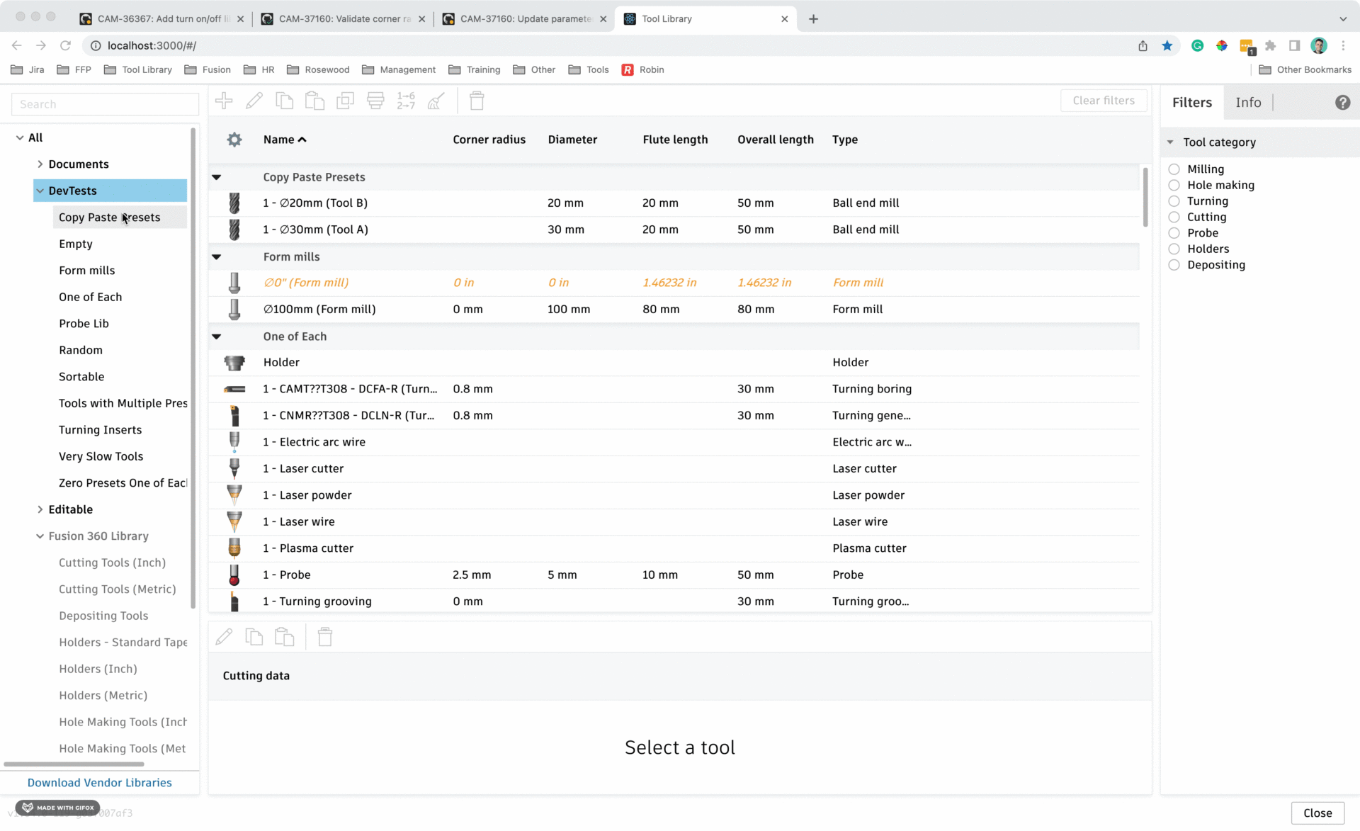
When you are using the tool library in manage mode, you can now have control over which libraries are loaded on opening of the tool library. This allows those of you using large libraries to only see tools you are interested in, resulting in higher performance.
Turn on and off unnecessary libraries
In the September release you will be able to reduce the loading speed of the tool library and decrease the density of tools by turning unwanted libraries on and off. This is achieved through the right click menu and the sample libraries will be turned off by default. We introduced a new behavior which will see no results returned through search or filter from libraries that are turned off.
New feedrates for probes
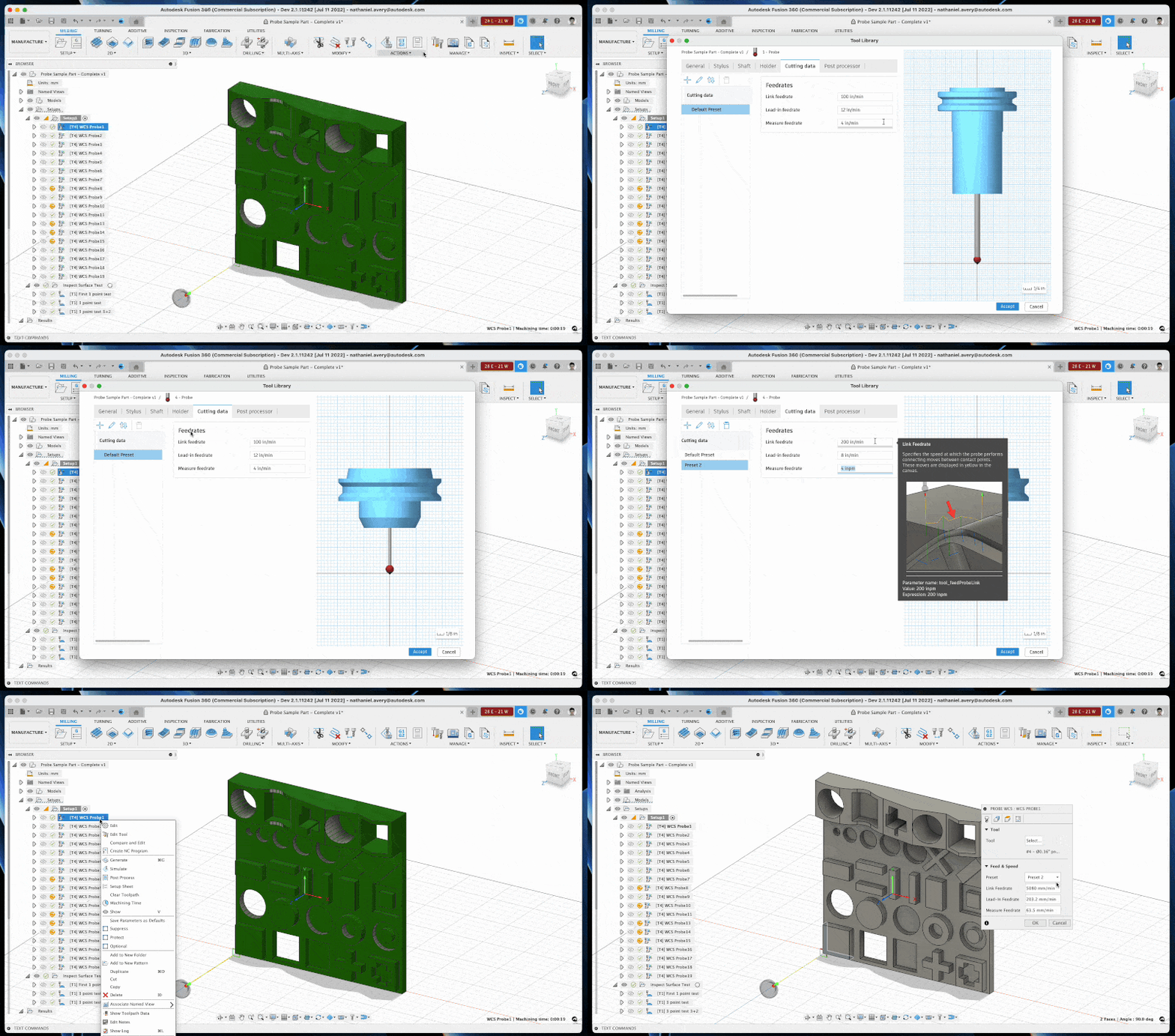
When you want to inspect a surface, you are asked to input three feedrate values in the operation dialogue: Link Feedrate, Lead-in Feedrate (renamed from ‘safe’). and Measure Feedrate. Previously in the tool library, probe tools have only one feedrate setting in the cutting data tab which is defined as ‘Lead-in feedrate’. We now have added these additional feedrates to the tool definition in the cutting data tab to align to this workflow. On tool creation, the default values will be as follows;
Link Feedrate = 3000 mm/min or 120 in/min
Lead-in Feedrate = 1000 mm/min or 40 in/min
Measure Feedrate = 102 mm/min or 4.00 in/min
MBD/PMI support for Inspection now officially available
PMI is product manufacturing information. It is data, such as 3D annotations, GD&T (geometric dimensions and tolerances), and other manufacturing information, which gets added to a 3D CAD model. PMI can be computer-readable (semantic) or graphical. The practice of adding PMI to create a fully defined digital model as the single source of truth, is known as MBD (model-based definition) or DPD (digital product definition).
In Fusion 360, you cannot create PMI. But you can open a design with PMI that was created in other CAD applications. By opening the design in Fusion 360, you can see the PMI and understand the original design intent.
Learn more about product manufacturing information (PMI).
Additive Improvements
New Defaults for how a Raft is created with FFF print settings
All FFF print settings have been updated to include new defaults for how a Raft is created. The new default Raft print settings extrude the filament at 25 mm/s, instead of 70mm/s, resulting in better print bed adhesion.
New Copper and Bronze meal FFF filaments added to FFF Print settings library
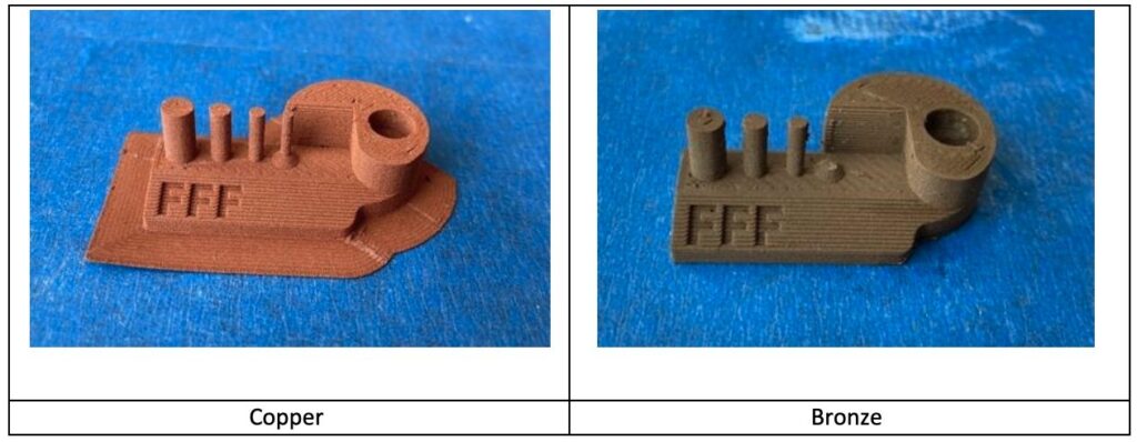
We are releasing 2 new FFF print settings in the Fusion 360 print setting library; Bronze and Copper 1.75mm. These are Filamet™ metal FFF filaments from The Virtual Foundry. These metal filaments have metal particles suspended in a plastic binder. Once printed, the parts can be sintered to achieve near fully dense parts. Due to the metal particles, these filaments are relatively abrasive and so it is recommended to use a hardened steel nozzle. A 0.6mm diameter nozzle is also recommended to reduce the probability of the nozzle clogging. Note: the print settings provided have been optimized for a 0.6mm nozzle.
Added ability to filter print settings by Machine Vendor within the Print Settings library.
With this release you now can quickly filter your print settings by Machine Vendor to find what settings works best for the machinery you own.

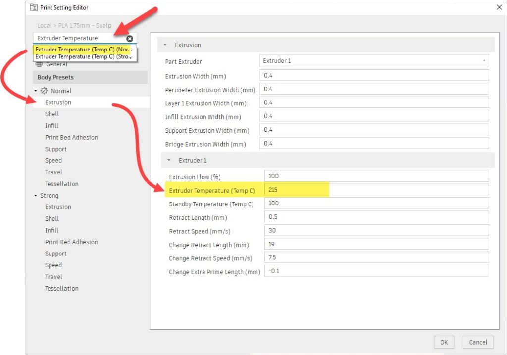
New Search Feature within the Print Settings Library
Long gone are the days of having to remember how to navigate to certain folders to edit common print settings. Now simply search for the setting you would like to modify within the print setting editor and immediately find what you are looking for.
Improvements to Metal powder bed fusion support structures.
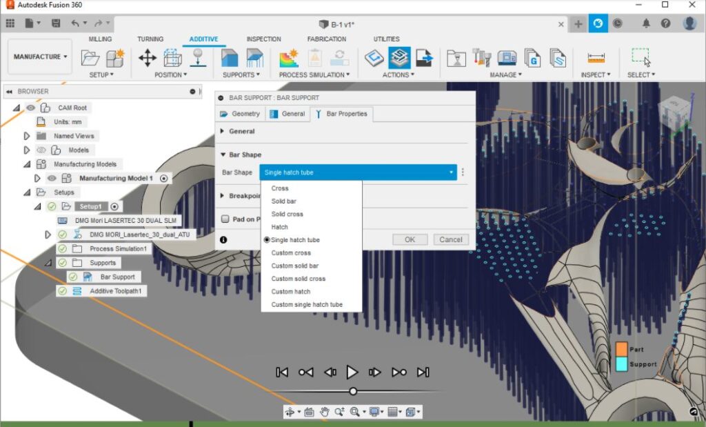
Added Single hatch tube to Bar Shape options within Bar supports. Support structures are a critical part of the Metal Additive manufacturing process. Bar supports are one the most common type of support structures. Fusion 360 can generate additive toolpaths for numerous metal Additive machines. A subset of metal additive machines (Example: DMG Mori LASERTEC 30 DUAL SLM) requires that the bar supports be processed as a single hatch when slicing. This improvement ensures that Fusion 360 generates the necessary support structures for all the metal 3D printers included in the machine library.
Learn more about adding bar supports.
Additive Process Simulation Preview Improvements
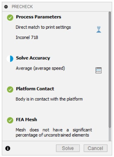
When setting up a metal powder bed fusion process simulation, Fusion 360 relies on you to select Print Settings for inputs for the Process Parameters. In this release we are expanding the list of print settings you can simulate to include Inconel 718 while printing with an Additive Industries MetalFAB1 machine, and Stainless Steel (SS36L) while printing with OneClickMetal machines. So you can now simulate the process using these print settings and get a direct match with the precheck dialog.
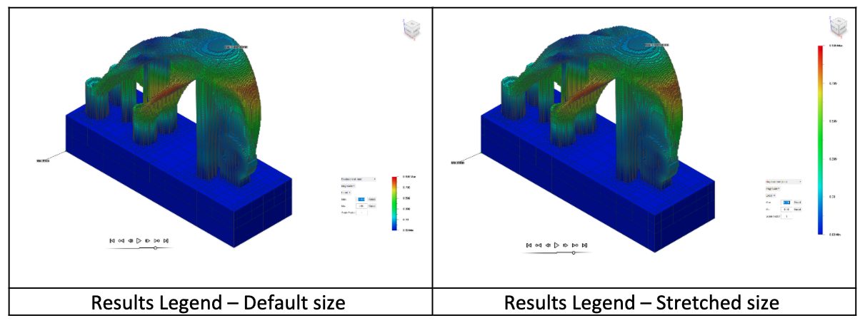
Additive Process Simulation Results Legend Improvements
You now have the ability to stretch and shrink the results legend to better suit your needs.
New Export Warped Shape tool in Results Viewing
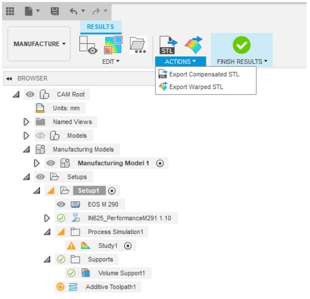
This new feature allows you to export a warped STL following completed Additive Process Simulation. This STL file will be distorted based upon the simulated displacements, and thus can be used to check against tolerances and perform validation studies.
Learn more about performing an additive process simulation.
New Manufacturing Previews
FFF Energy Consumption Prediction

The FFF energy consumption prediction preview gives you a predictive energy consumption value when generating toolpaths for additive manufacturing (FFF only). Manufacturing energy consumption, alongside material usage, is a key contributor to the total CO2 emissions during the realization of designs. We want to start giving you visibility into how much energy your manufacturing toolpaths are consuming, helping you make more informed decisions and altering your design and manufacturing practices with the aim of reducing overall operational impact. The FFF energy consumption calculator is the first step in this process, by analyzing your generated tool paths and taking different key variables (Build plate, Print Temperatures, Print Speed and Print time) into account, this new feature calculates and displays a predicted energy consumption value within the print statistics tab.
Learn more about displaying print statistics.
Center-to-Center Distance for Manual Inspection

This preview lets you choose how to measure the distance between the centers of two holes or bosses in a manual inspection. If your measuring instrument does not support measurements of center-to-center distances, Fusion 360 can calculate the distance using the diameters of the holes or bosses and the maximum or minimum distance between them
Learn more about measuring center-to-center distances.
Optimize Open Pockets for Steep and Shallow

The Optimize Open Pockets for Steep and Shallow preview improves cutting conditions such as tool entry and exist position, which may result in a better surface finish. This preview is available when using scallop to machine open pockets in shallow areas and will later be included with the Machining Extension.
Machine V2

This is the 2nd version of our machine configuration tool preview. The Machine Configuration puts all of the information about your machine in one place. Some of this information is used to control the manufacturing output (NC code) and the post processor functionality. Use Machine Configurations to define your available machines and resources. These configurations can automate the settings in your Job Setup.
Learn more about Machine Configuration
API
You guys asked and we delivered! In this update we have exposed some of the View Cube functionality in the Fusion 360 API.
Summary of Fixes
In this product update, we’ve made 72 improvements and fixes that came directly from your forum posts and interactions with our support team.
Looking for a more in-depth break down? Check out this forum post.
Live with the Experts

Join us for this exclusive 60-minute live event with Fusion 360 experts. We’ll cover all the latest features and functionality in Design & Documentation, Manufacturing, Simulation, Electronics & Generative Design. We’ll show live demos of the latest improvements, show off some tips & tricks, and open the floor for plenty of LIVE Q&A.
We have 2 sessions on Wednesday, September 21st for you to choose from, both identical in content, just at different times. Click the links below to sign up. Looking forward to seeing you there!