(v.2.0.17457) – October 9 , 2023
- We fixed a bug that occurred when switching to a newly inserted Configured Design.
- We fixed a handle error issue impacting some users creating Configurations for the first time.
- We fixed an issue that occurred when changing between Configurations which caused the wrong model to appear within the model window.
- We fixed an issue that occurred when a user who was invited to a project opened a Configured design causing an email to incorrectly go out to the project owner notifying them of a change to the design file.
- We fixed a variety of crash issues relating to Configurations.
- We fixed a crash issue occurring when opening certain files containing T-spline surfaces.
- We fixed a CPU utilization issue which occurred when waking Fusion from a sleep state.
(v.2.0.17453) – October 1 , 2023
- We fixed a crash issue that occurred when opening certain files while on a mac.
- We fixed a crash issue that occurred when opening a newly saved file that included a hatched polygon in Fusion Electronics.
- We fixed a crash issue that occurred when opening a .cam360 file from the data panel.
- We fixed an issue causing T-spline conversion not to function as expected.
- We fixed an issue in the Manufacturing workspace where tool and part attach points were not kept aligned to the XZY of the CAM document.
- We fixed an issue where saving a NC Program in a Network location was not functioning as expected.
- We fixed an issue causing certain Post Processors to fail due to missing dlls.
- We fixed an issue causing the network diagnostic test in Fusion service utility to fail.
- We fixed an issue where Drawing template fails to correctly populate data.
- We fixed an issue impacting non-English languages where users were unable to change arrowhead types within the Drawings workspace.
(v.2.0.17244) – September 19, 2023
What’s New Highlights
This September we have fantastic new features, updates, and improvements we can’t wait to share with you. But before we get into all the details, here are a few of our favorite highlights from this release:
Introducing Configurations:
– Create new Configured Designs from scratch
– Document your Configured Design in Drawings
– Switch between Configurations and Manufacturing
Increased Efficiency Across Workspaces:
– New Design Sheet Metal Rip Feature
– Improved 3D Sketch Experience
– Bar Support Improvements for Additive Manufacturing
– New Angled Volume Supports for Additive Manufacturing
Live with the Experts: What’s New in the September 2023 Release
Want to learn more about all the updates coming to Fusion 360 this September? Join us on Thursday, September 28, 2023 for a LIVE webinar where we’ll dive into improvements around flexibility, control, and programming efficiency, show off some tips & tricks, and open up the floor for LIVE Q&A.
We have 2 sessions running for you to choose from, both identical in content, just at separate times. Click the links below to sign up. Looking forward to seeing you there! `
Register for 9am PDT | 12pm EST | 5pm BST
Register for 10:00am BST | 11:00am CEST | 2:30pm IST
Usability
Previews Move to the Insider Program
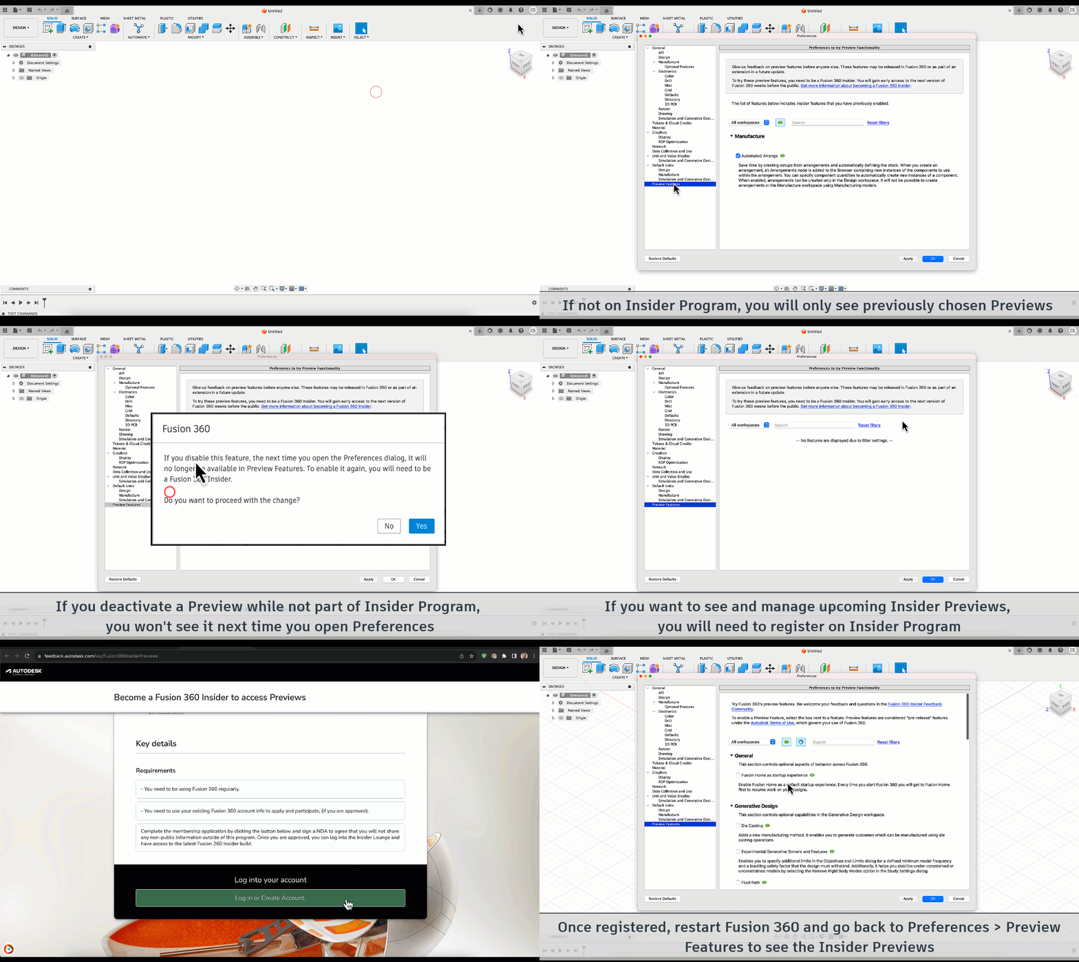
To improve efficiency in communication with those of you who are testing Public Previews, we have made some changes that you will see as part of the September release. As of September 2023, all previews will only be available if you are registered through the Insider Program. This means if you would like to gain access to preview functionality you will have to register for the Insider Program. If you previously had a preview activated, no need to worry, you will be able to retain this functionality until you decide to turn that preview off. Additionally, with this move comes the renaming of how we refer to previews. As of this update “Public Previews” will now be referred to as “Insider Previews”.
We anticipate that you may have more questions, so we encourage you to check out our FAQ article for additional information.
SpaceMouse SDK v4 now available on macOS
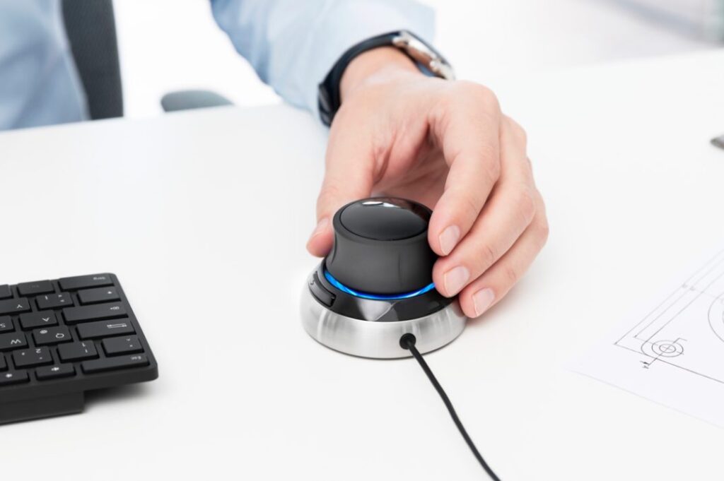
Fusion 360 now supports SpaceMouse SDK v4 on macOS in addition to Windows. After installing the latest drivers from 3Dconnexion, SpaceMouse users can now enjoy newer features like Lock Horizon with Fusion 360.
General Performance Updates
Performance is a key area of focus for us, evident from some of the improvements we’ve made over the past few product updates. This update continues to improve on the usability, assembly and modeling performance of Fusion 360.
Usability:
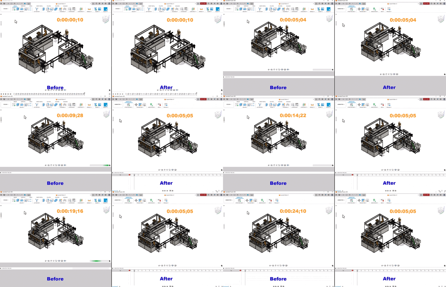
- The performance of scrolling the browser is now much faster than before.
- Expanding the browser node of external component has been improved about 106% for some design files.
- Switching document tab for some design files can be immediately done without delay anymore.
- Switching to Animation workspace from Design workspace has been improved up to 7.3x for large assemblies.
- The memory consumption for Export workflows is now reduced by about 1.7x.
Assembly:
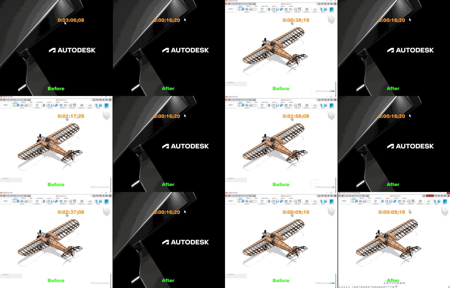
- Closing Fusion 360 while a large assembly is open is up to 6.6x faster.
- Closing large assemblies on Mac OS is up to 4x faster now.
- Fusion 360 is now more responsive during edit Joint or add As-Built Joint while in Edit-in-place mode for large assemblies.
Modeling:
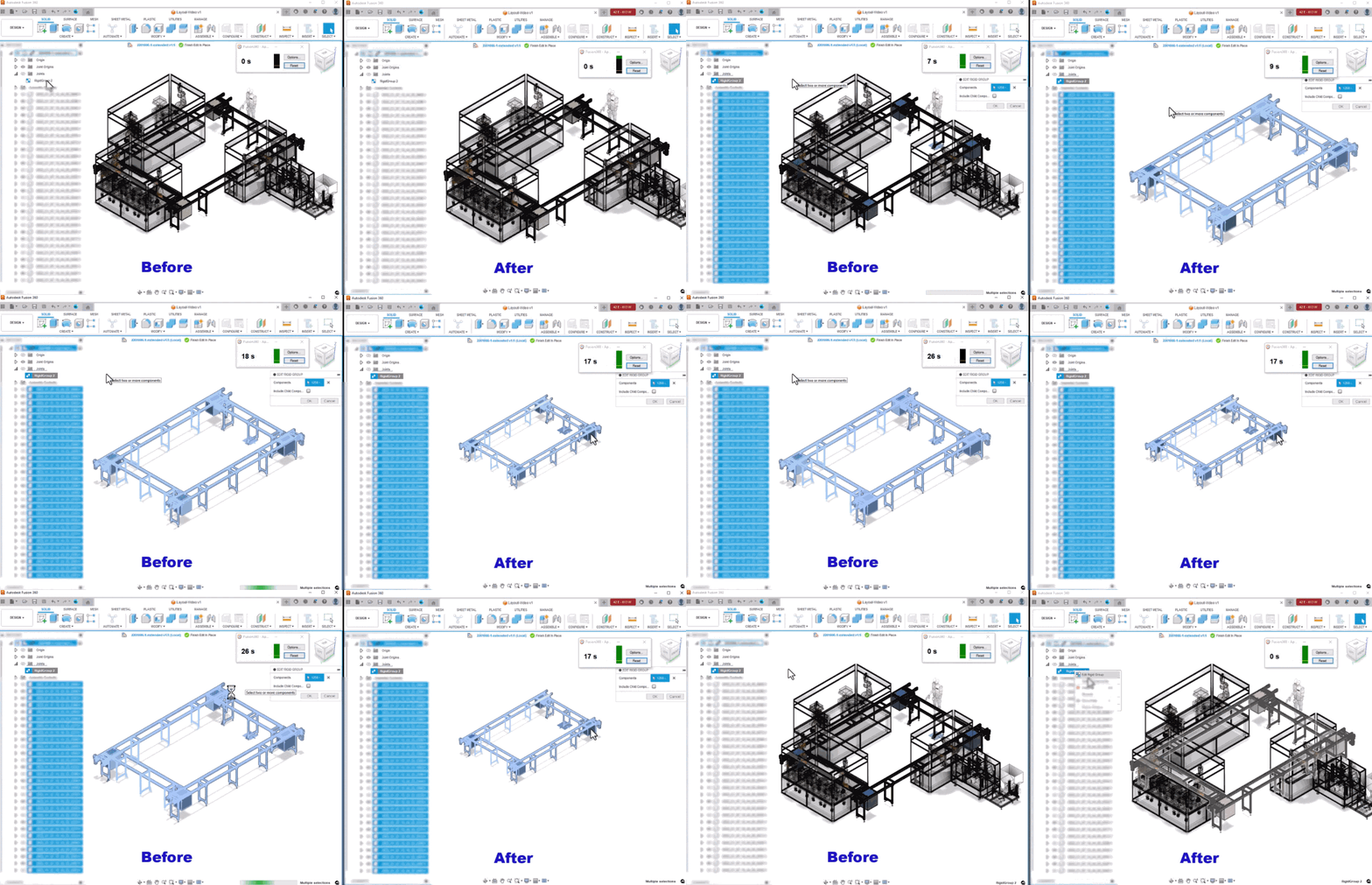
- Performance of the start/finish/cancel edit Joint command is significantly improved from the top large assemblies.
- Opening some model files is now up to 1.5x faster than before and this optimization can also benefit the compute of these designs.
- Open STEP file has improved in efficiency.
- Hide Design History is up to 31.6x faster and Copy to New Design is about 4.6x faster for those design files.
- Preview performance of Insert SVG and DXF has improved.
Design
Introducing Configurations
The moment many of you have been waiting for is finally here! As of the September 2023 update you will now be able to use Configurations. Configurations lets you reuse parametric logic to create variations of a design. You might use Configurations to author a family of parts in a product line, define different material and appearance options, create complex variant assemblies, or represent stages in your manufacturing workflow.
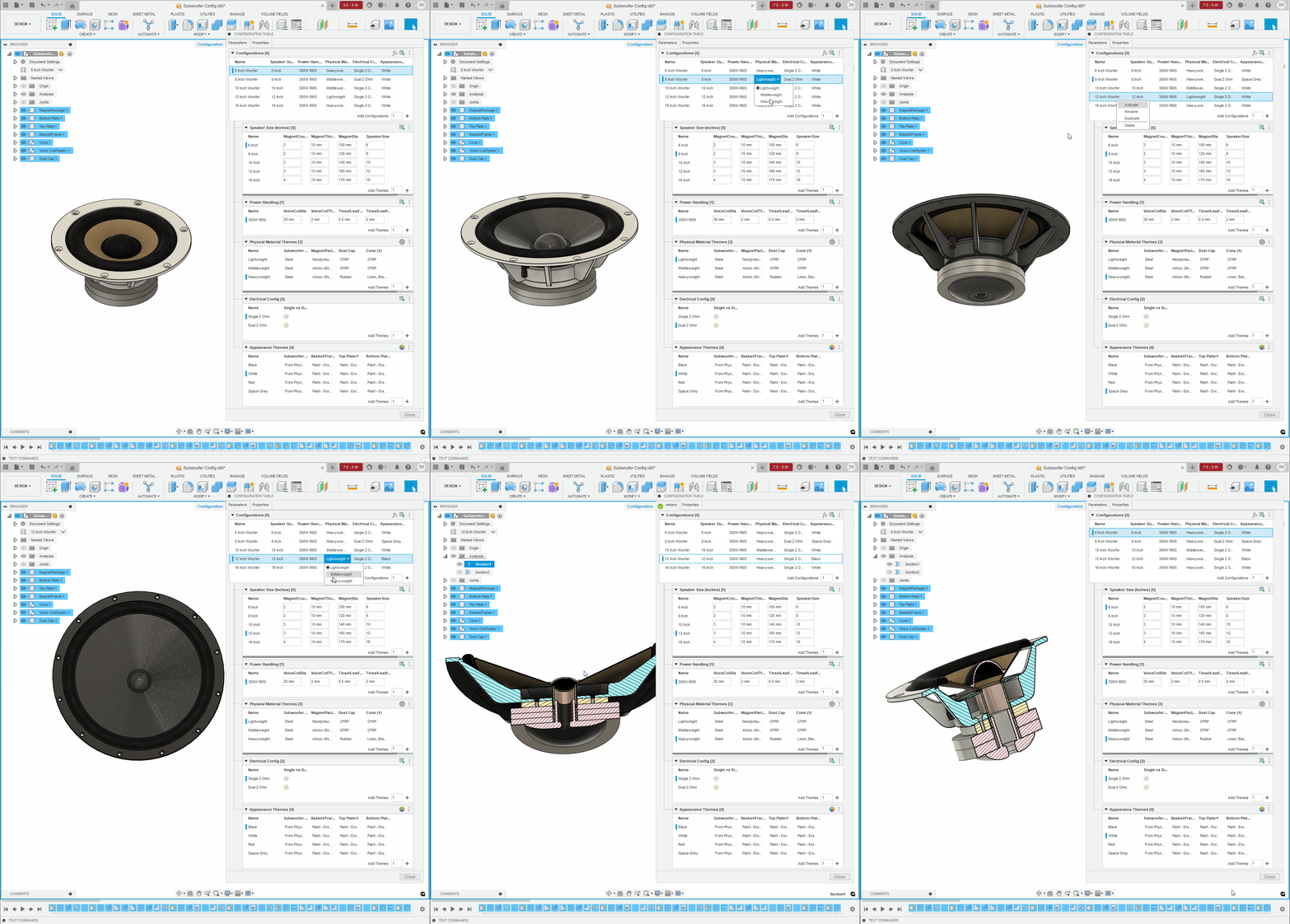
In the Design workspace, use the commands on the new Configure panel to create new Configured Designs from scratch, or open an existing Standard Design and configure it.
Once you’ve created Configurations, you can use them in workflows all over Fusion:
- Configurable features and objects are highlighted in blue in the Browser and Timeline
- Click a highlighted feature or object to see its list of configurable aspects, then check the aspects to add them as columns in the Configuration Table
- Add Configurations to the table and edit values for each Configuration
- Double-click to activate different Configurations to see their differences or use the dropdown list in the Browser when the table is closed
- Move similar aspects to Custom Theme Tables to minimize complexity or author more efficiently
- Insert or derive them into other designs
- Configure inserted Configurations to create nested Configurations
- Create a Drawing for each Configuration
- Copy a Drawing and Switch Configuration to save time creating drawings for each Configuration
Switch to other workspaces and activate different Configurations to use them in different environments:
- Create Storyboards in Animation
- Create rendered images in Render
- Setup, solve, and compare Simulation studies
- Generate and compare Generative Design studies
- Create Manufacturing setups and generate toolpaths
- View Configured Designs and their Configurations in Fusion Team
If you don’t immediately see Configurations in your toolbar, no need to worry. We will be releasing Configurations slowly over the course of the next month, so if you do not see it today you should be able to use the functionality very shortly. By adopting a staggered approach, we aim to seamlessly integrate this powerful feature into the Fusion 360 ecosystem.
Check out our self paced learning to get up and running with Configurations.
Or learn more about Configurations in the documentation, if reading is more your speed.
Note: This feature will only be available for commercial and education licenses. If you want to try out Configurations but do not yet have a commercial license, try out Fusion 360 for free today with a 30-day trial. As part of the trial period, users will get immediate access to the feature.
New Sheet Metal Rip Feature
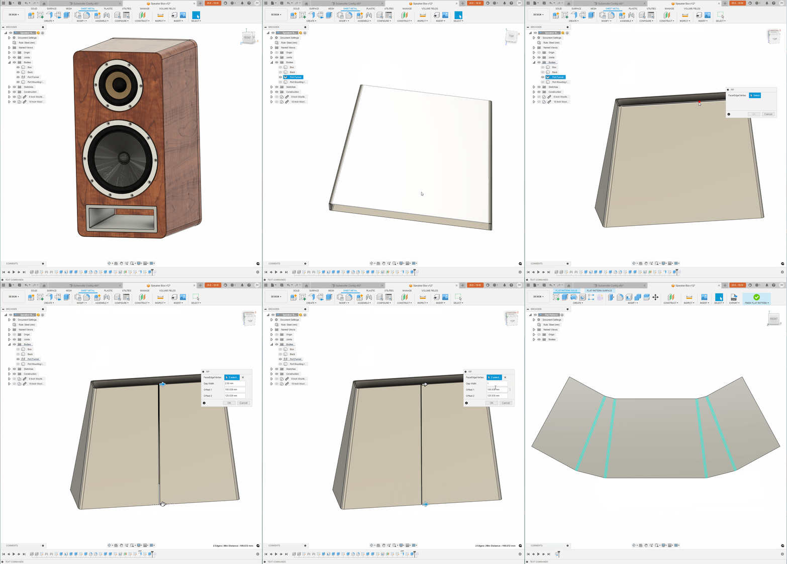
Sheet Metal Rip has been a long-awaited feature within the Sheet Metal workspace, and we are excited to announce it’s finally here! If you have ever been stuck within the sheet metal workspace of Fusion 360 this is definitely a feature to check out. What the Rip tool does is automate the modeling of a split in your sheet metal part that is needed to unfold, flatten, and manufacture the part. To access this tool simply go to the modify tab, select the face you would like to rip or select two points to define the start and end of the rip, and the width of the gap to be created. Just like that you can now use the new rip tool to create a tear so that you can unfold/flatten your sheet metal bodies with ease! This feature will be especially useful for those of you creating lofted sheet metal parts like air ducts, oven hoods or funnels.
Improved T-Spline intersection transitions in Bevel Edge
Form contextual environment > Modify > Bevel Edge
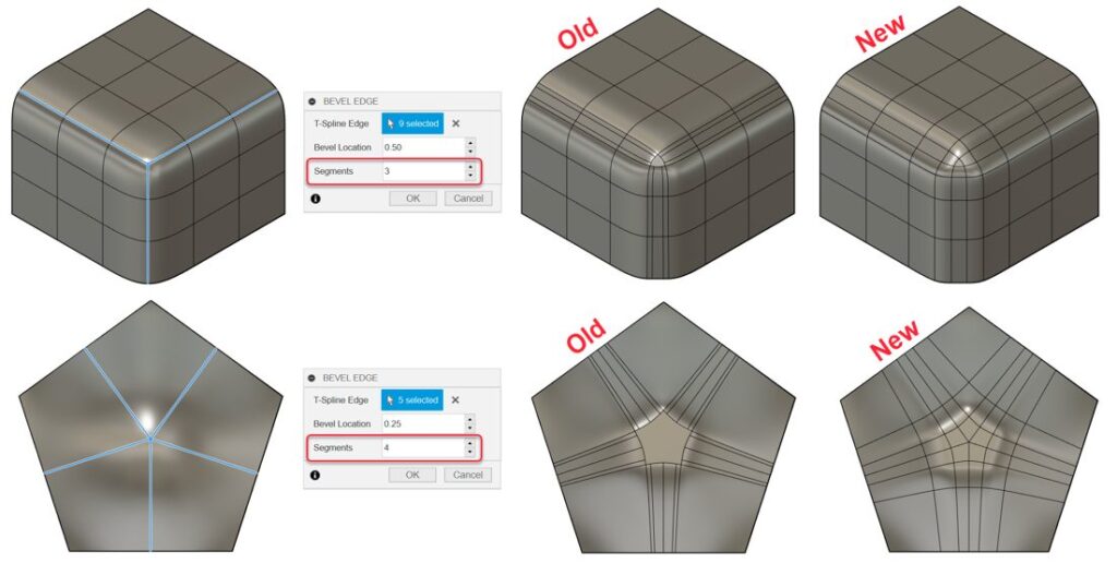
Previously, the non-quadrilateral faces that were created at the intersection of selected edges interrupted the flow of incoming curves. Now, segments are evenly spaced and continue along the selected edges through the non-quadrilateral face to create smooth curve transitions.
Improved setting options for non-quadrilateral faces in Subdivide
Form contextual environment > Modify > Subdivide
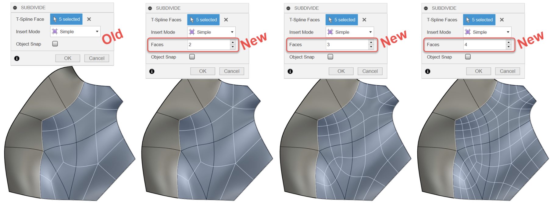
Previously, you could only subdivide a non-quadrilateral face at its center. Now, you can specify the number of faces to subdivide a non-quadrilateral face into along each edge.
Learn more about how to Subdivide a T-Spline face.
Improved 3D Sketch
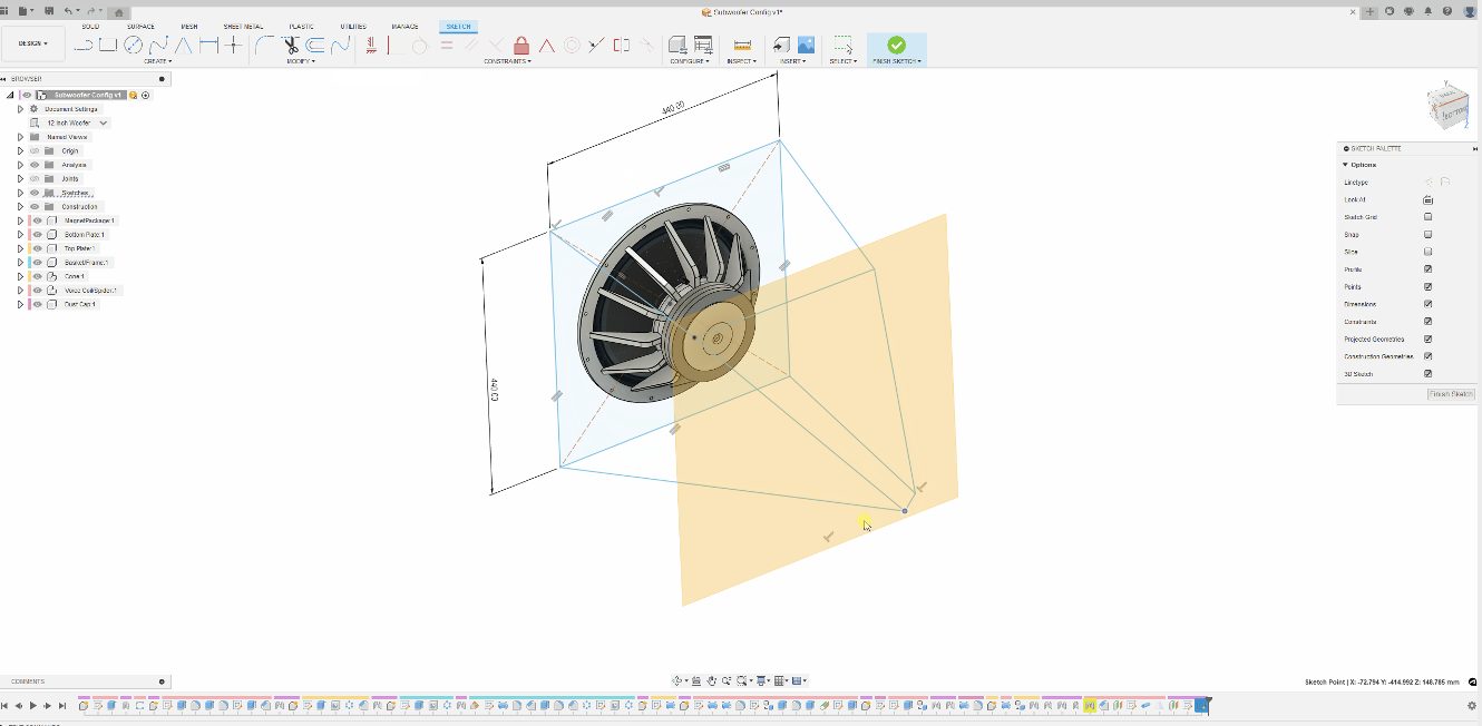
As of this update you will be able to apply constraints to lines and points in 3D space. These constraints include point coincident to a surface; line parallel to a planar surface; line on a planar surface; distance between point and planar, cylinder or spherical surface; distance between line and planar surface; perpendicular between line and surface; perpendicular between spline (both cv and fit point) and surface. Additionally, points and lines can now be dragged around the canvas like in 2D sketch giving better control over your points and lines in 3D space.
Introducing Change Units for Parameters
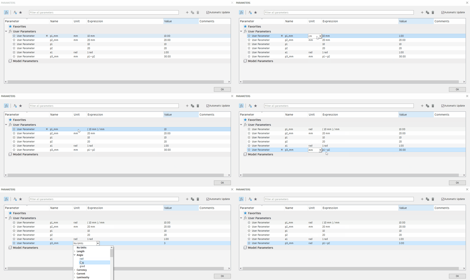
Previously, when you created a parameter, its units were set in stone and could not be changed. This is no longer the case! You are now able to change the units of an existing user parameter.
Note: there is a restriction in place for now that the parameter being edited cannot be in use in order to change the units.
Generative Design
Improved Solver Robustness for Handling Geometry Separations
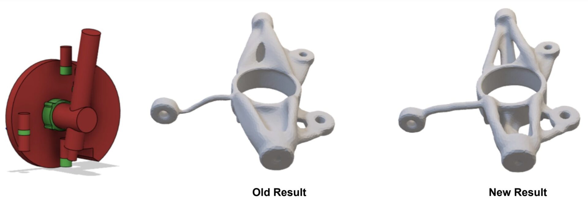
In this update, we have added a new level of robustness to our solver in the Structural Component study to help handle geometry separations. Geometry separations were common in setups that had multiple loads in a single load case that greatly varied in magnitude, had preserve bodies with no loads or constraints applied, or had constrained preserves that were not actually needed for the overall performance of the part. Results often looked incomplete with minimal material removed due to the solver stopping early. The robustness improvements in this update will help keep the design space connected and allow the solver to iterate further, ultimately giving you a better result.
Drawings
New Switch Configurations
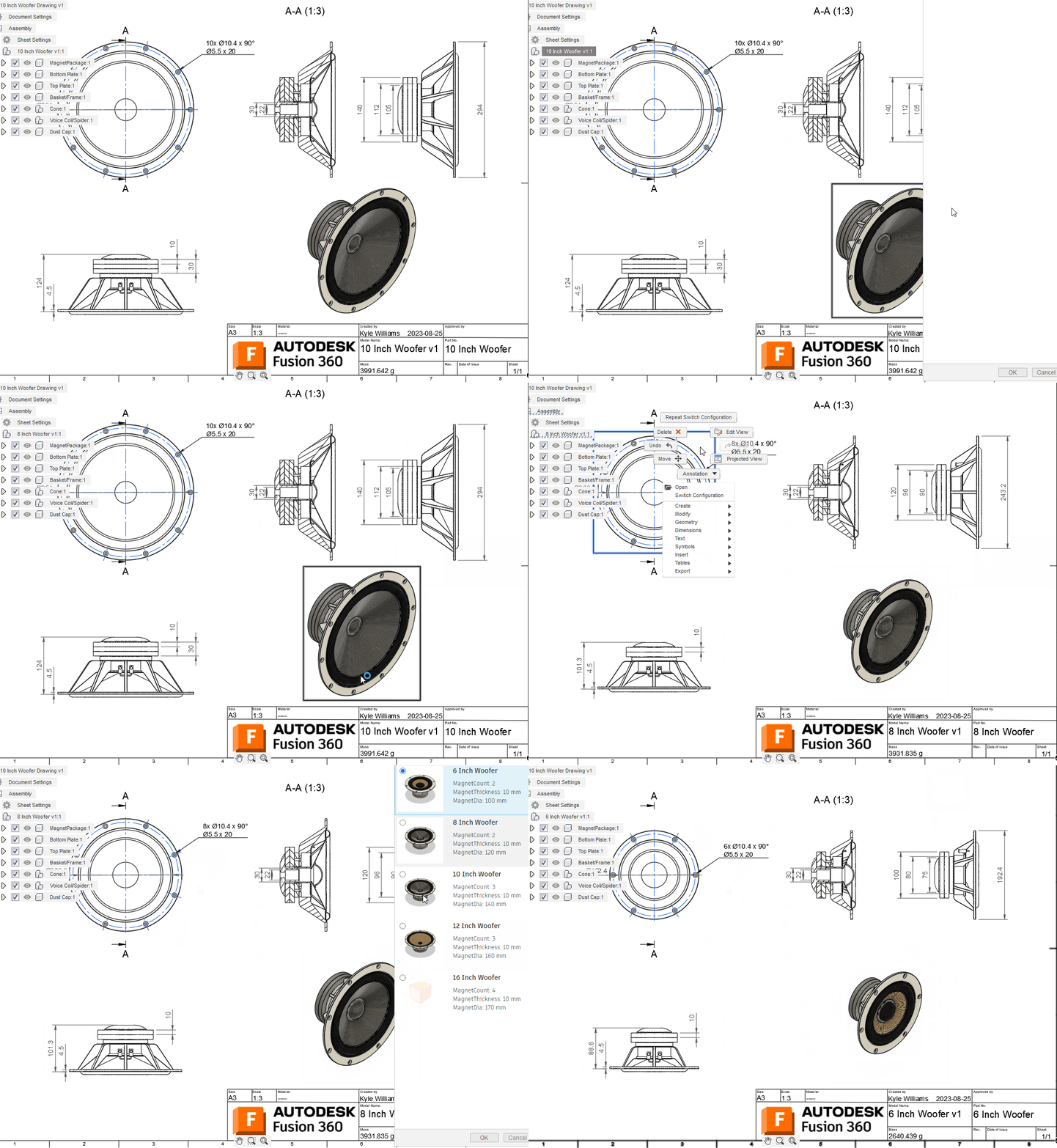
Document your configured design, and when you’re ready, simply switch out the configuration and “Save As” to create a new drawing. Your views, dimensions, and tables will all update to match the new configuration. Switching is easy, via the browser, or by simply right-clicking on a view.
More Arrow Head Types

You’ve been asking for more customization options, and we’ve been listening. With this update, you can now choose from 19 new Arrowhead shapes in addition to the default “Closed Filled”. These new shapes can be set for Dimensions, Leaders, Balloons, Bend IDs, and Hole IDs. You can mix and match Arrowhead types to create the perfect look for your drawing. For example, you could use the “Architectural Tick” for Dimensions and “Right Angle” for Leaders, with other shapes mixed in to achieve the customization you need.
Learn more about Arrowhead types.
Expanded Line Width Groups
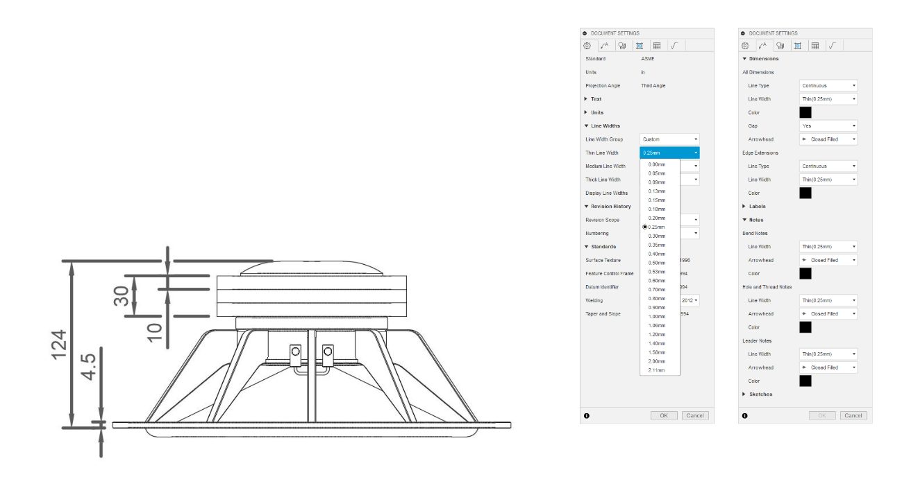
Line Width Groups are now far more flexible. Setting your Line Width Groups to “Custom” in Document Settings, allows the flexibility to choose practically any line width for your “Thin”, “Medium ” & “Thick” line groups. Putting you in control of how your design is showcased to the world.
Learn more about Line Width Groups.
Simulation
Default Target Mass changed from 30% to 60% for Shape Optimization Study
Simulation > Shape Optimization > Shape Optimization Criteria
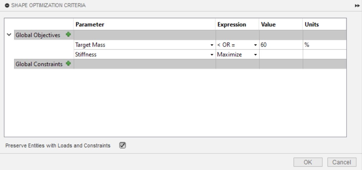
We have changed the default Target Mass Criteria for Shape Optimization Study from 30% to 60%. Based on the type of models that are most commonly run for Shape Optimization, the new target is much more likely to be achieved without any issues or failures. If a different value is needed you can always change this to better suit your needs.
Improved Error Message for Shape Optimization Job Failure
Simulation > Shape Optimization
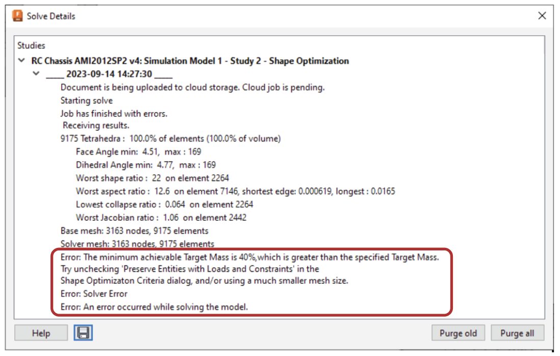
We have improved the error message that appears when a Shape Optimization job fails which will give more clarity to the user about the nature of the error and what the user can do to avoid it.
Improvements to Quasi-Static Event Simulation Study
Simulation > Quasi-Static Event Simulation
We have made some really good improvements to the Explicit Solver targeting the Quasi-Static Event Simulation. We have improved the kinetic energy tolerance in the solver which will result in better convergence and reduce failures of Quasi-Static analysis. You will also see a substantial improvement in time to results for Quasi-Static Event Simulations.
Manufacturing
Using Design Configurations in Manufacturing
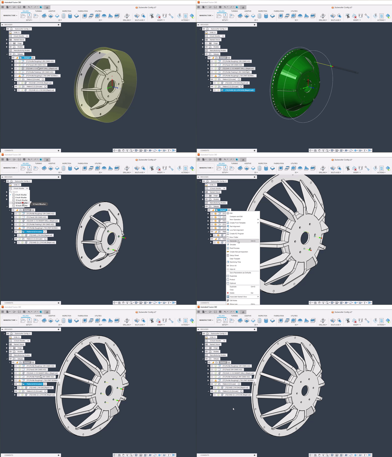
Configurations and configured designs are important functionality for ‘professional’ CAD systems. Many products are available in a ‘family’ of multiple related configurations, or variations, of fundamentally the same product- for example different sizes and colors. A configuration is one particular instance of such a product, and a configured design is the collection or ‘family’ of all the individual configurations or variations. This provides the benefits of parametric design for the overall product ‘family’ so that design changes update all members together with support for ‘customization’ through parameters that vary across different family members.
For the initial release of Configurations, manufacturing will simply ‘consume’ design configurations by reacting ‘appropriately.’
Changing configuration effectively appears as a design change, invalidating toolpaths. When you select a new configuration, this shows up as a design change. Toolpaths are invalidated, and you have to regenerate the toolpaths for the selected configuration.
Although not ideal, this overall behavior is reasonably intuitive if the design and the model are the same.
Flow (Preview) Replaces Flow
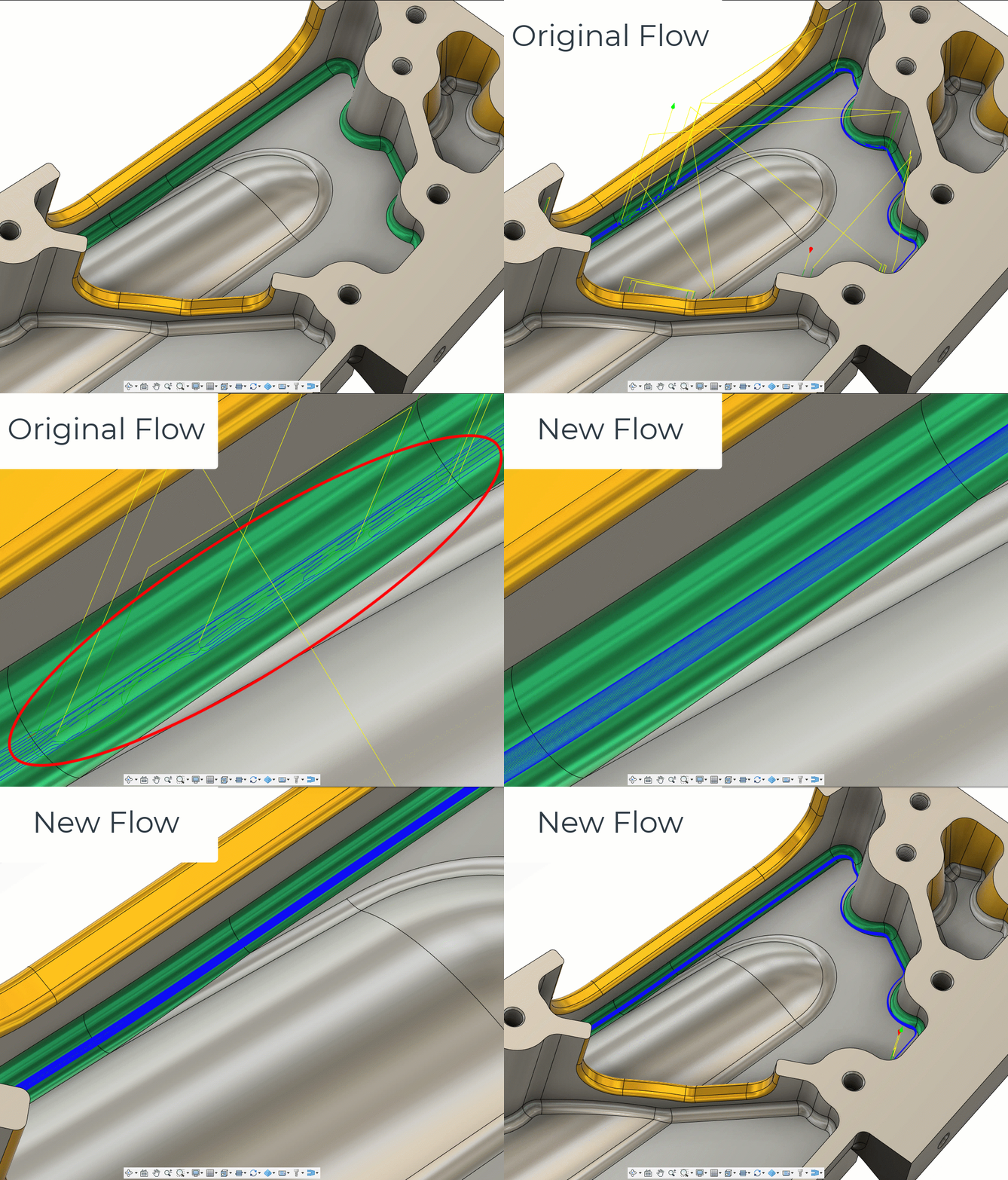
Last year we gave you an enhanced Flow toolpath called Flow (Preview). This means that we currently have two Flow style strategies in the 3D Toolpath section, the Flow toolpath, and the new enhanced Flow (Preview). The original Flow creates the toolpath on the underlying triangular data. What this means is that usually you get a decent quality toolpath but in instances where you have disconnected triangles or poorly trimmed geometry, the toolpath can result in broken segments with unnecessary leads and links which leave material on the part. Making it likely that you have to re-machine with another toolpath or take up costly manual work later down the line.
The new enhanced Flow toolpath, however, is calculated on the underlying surfaces. Meaning less wavy transitions between toolpath segments creating a better-quality surface with less manual finishing required afterwards. Additionally, enhanced flow now supports a defined step over rather than number of steps required, automating the enhanced flow toolpath creation. Since we have been seeing far more robust, reliable, and controlled toolpath creation from the use of the enhanced Flow toolpath, we are replacing the Flow Preview algorithm with the original flow. If you still require Original Flow, you will still be able to access this function by switching it back on within the preference tab. If you do decide to turn it on, you’ll now have two toolpaths; the Flow and the Old Flow.
Geometry Features Enhancements
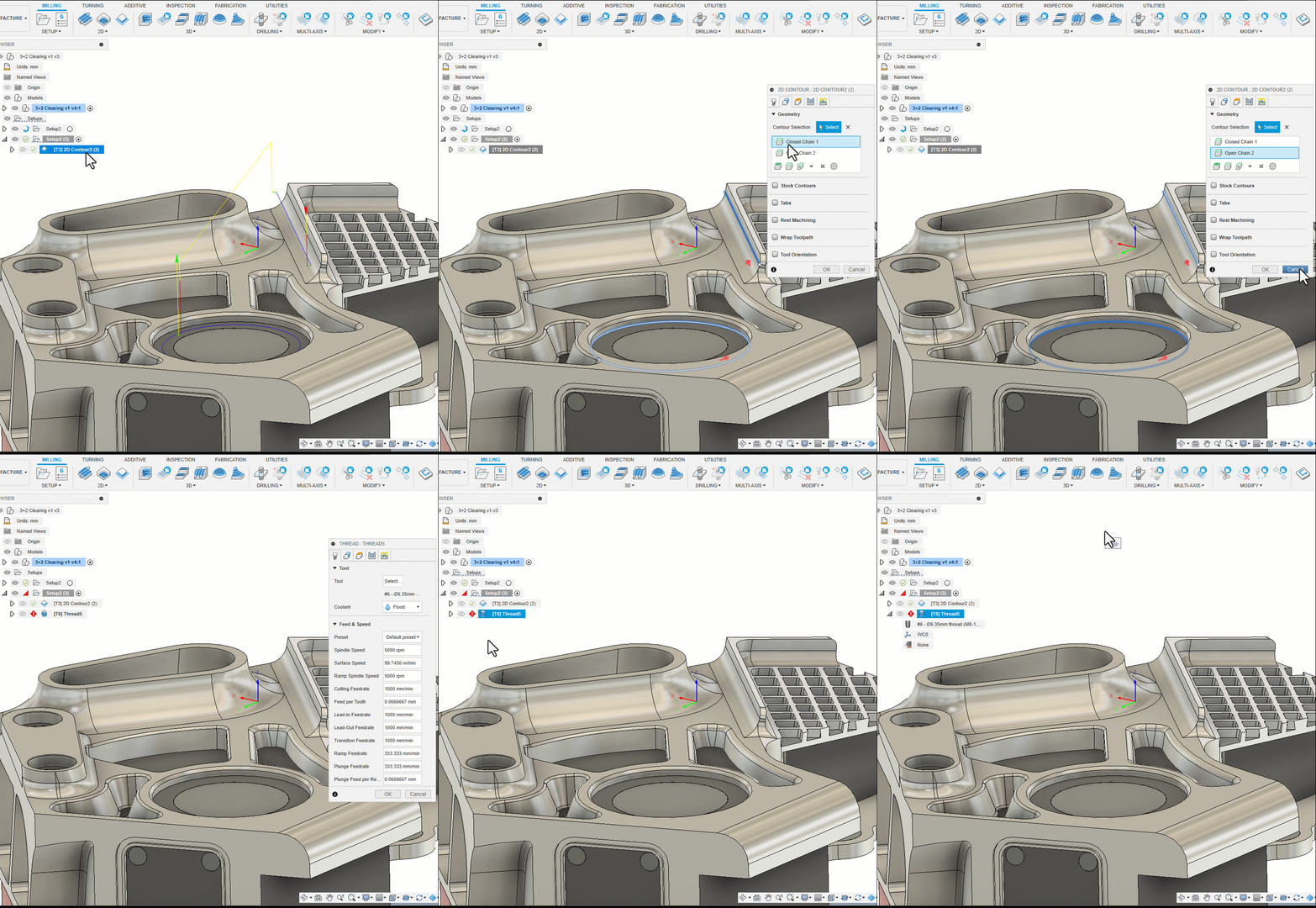
Improved Thread, Bore and Circular (and other) operations
To be support the creation of template workflows and automation it is now possible to create and save Thread, Bore and Circular (and other) operations without the absolute necessity to create a valid geometry selection. If the selection is invalid you will now see a warning but will be able to save and continue (this was previously impossible because the error prevented you from saving and moving on). The main application for this change is so that when you are creating templates for automation workflows- you can prepare and save the document in an interim state, to record intent with whatever data and information is available, even if this is incomplete- to minimize the user intervention required when the currently missing data becomes available. For example, you might need to save a manufacturing document template without the final CAD, but with setups, operations, and geometry selections. This change will allow you to create a completed document more quickly and with fewer inputs when the CAD becomes available.)
Improved Geometry Feature Selection Identification
Currently all chains (for example) are called the same thing making identification difficult. With this update Geometry Feature selections will be named, to make identification and reuse easier. This change means that selections now have a suffix of a space and number, for example Silhouette 1. Chain selections also have a prefix of ‘Closed’ or ‘Open’ for example Closed Chain 1.
Minor UI Enhancements / Correction
Silhouette selection dialog shows ‘Bodies’ (only bodies can be selected, not bodies or faces as misleadingly shown previously). Selection from “Pocket Recognition” are now shown as ‘Pockets’ rather than ‘Pocket Recognition’ as previously.
New and Improved Post Processors Update

Looking for the latest post processors and machines updates? This September we released a ton of new updates and improvements to many of the open-source Post Processors and Machines we offer for free. Within this release you will find the addition of milling post processors for Machine Tool Camp and Siemens, as well as a new additive post processor for BIQU, and improvements to many milling post processors, mill-turn post processors, and turning post processors. Additionally, we added new machines to our Machine Library, updated and improved our Workholding library, and improved functionality around the Autodesk CAM Post Processor engine.
To learn more check out the forum post here.
Missed the August update? Check out the forum post here.
Additive Manufacturing
Bar Support Improvements
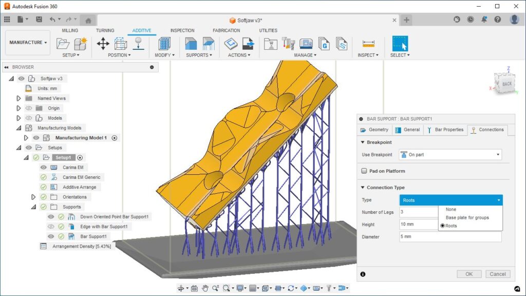
Volume Supports and Bar supports are the two most common support types used in additive manufacturing today. With this release we are improving the user experience of all Bar support types so that not only they get more advanced part and build plate connectivity options, but also look and feel more like the Volume supports.
With the September release, you now can add Roots to Bar supports so that your bars have additional connection points to the build plate for added stability. Instead of adding Roots, if you chose to add a Base Plate to connect your Grouped Bar supports or Grouped Lattice Volume supports to the build plate of your 3D printer, you now have additional options to create a solid Base Plate vs. one with hole patterns you can manipulate. The ability to control the pattern type of a base plate included with a grouped bar and lattice volume supports, unifies the support generation experience between Bar Supports, Lattice Volume Supports and Base Plate Supports.
The newly added Roots option, as well as the existing Base plate for groups option now reside in a new tab called Connections within the Bar Support and Volume Support dialogs respectively. A new Connections tab has also been added to the remaining two Bar support types (Down Oriented Point Bar Support, Edge with Bar Support). This new tab contains all the settings you can control around how your bar supports will connect to your components such as the shape and dimension of the breakpoint. It also contains the option to design and generate individual pads for each bar to enhance build plate connectivity and ease of removal from the build plate.
In addition, you can now control the visibility of each support structure by selecting the eye icon next to that support line item within the BROWSER just like how you can turn on/off the visibility of any component.
Fill the Available Build Area or Volume with a Selected Component

Automatically fills the empty space within the active additive setup with duplicates of a selected component.
In 3d printing with certain technologies (example: SLA, DLP, SLS and MJF) it is more economical to pack more parts in to the available build space. By doing so you can not only reduce the per part cost, but in certain cases you could also print more parts in the same amount of time. This new feature allows you to select a given component, and duplicate it within the active Manufacturing Model as many times as possible to fill the available area or volume in your 3D printer, while keeping the orientation of the part the same. It also automatically adds those components to the active additive setup and arranges them based on your desired arrangement criteria.
Learn how to fill a build volume with components.
Arrangement Statistics for an Additive MFG Setup
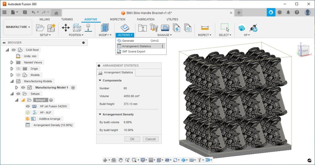
After arranging parts in 2D or 3D within an additive manufacturing Setup, you can now inspect the build and find out about the number of parts within your build volume, as well as your arrangement density based on printers available volume or build height of your arranged components.
Learn how to display arrangement statistics.
New Angled Volume Supports (Additive Extension)
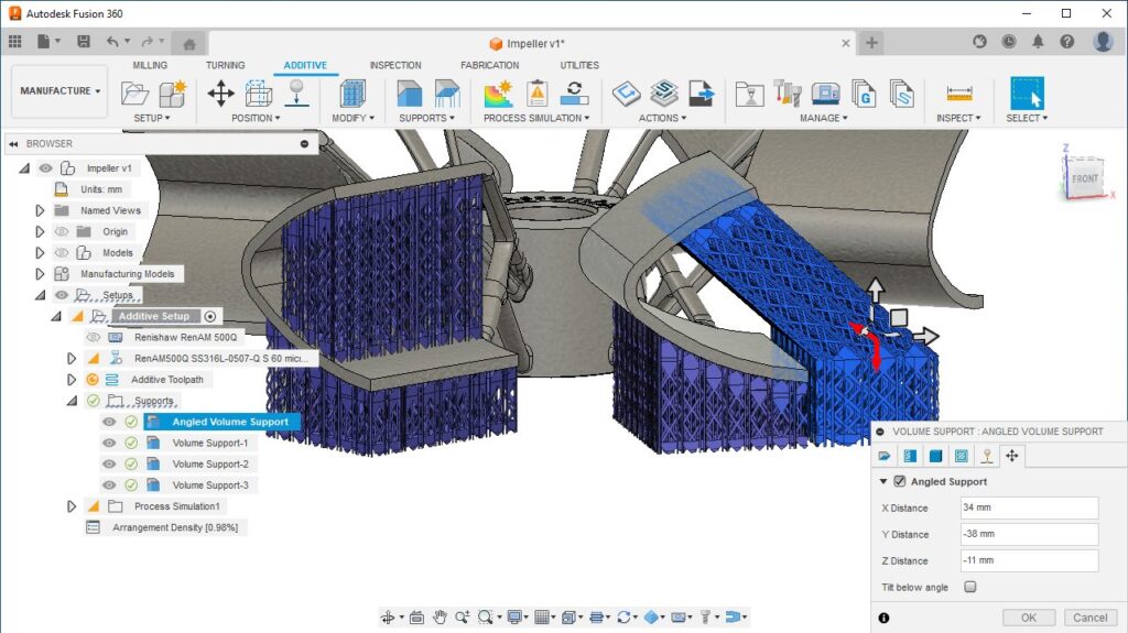
Angled volume supports are graduating out of tech preview and are now available to users with access to the Additive build extension. When generating volume supports for components in an Additive setup with an MPBF (metal powder bed fusion) 3Dprinter, it is better to avoid having your support structures come in to contact with the upskin sections of a part. By accessing the Angled Volume Support tab within the Volume Support dialog, you can introduce a pivot point in the support path, so that the support structure can bend around that point to keep away from surfaces directly below the supported face. Using this technique, you can minimize the time spent during support removal and additional post processing steps such as cleaning up blemishes on upskins where supports were in contact with your parts.
Learn how to add a Volume Support structure.
Additive Multi Axis Deposition Toolpaths Graduates (Additive Extension)
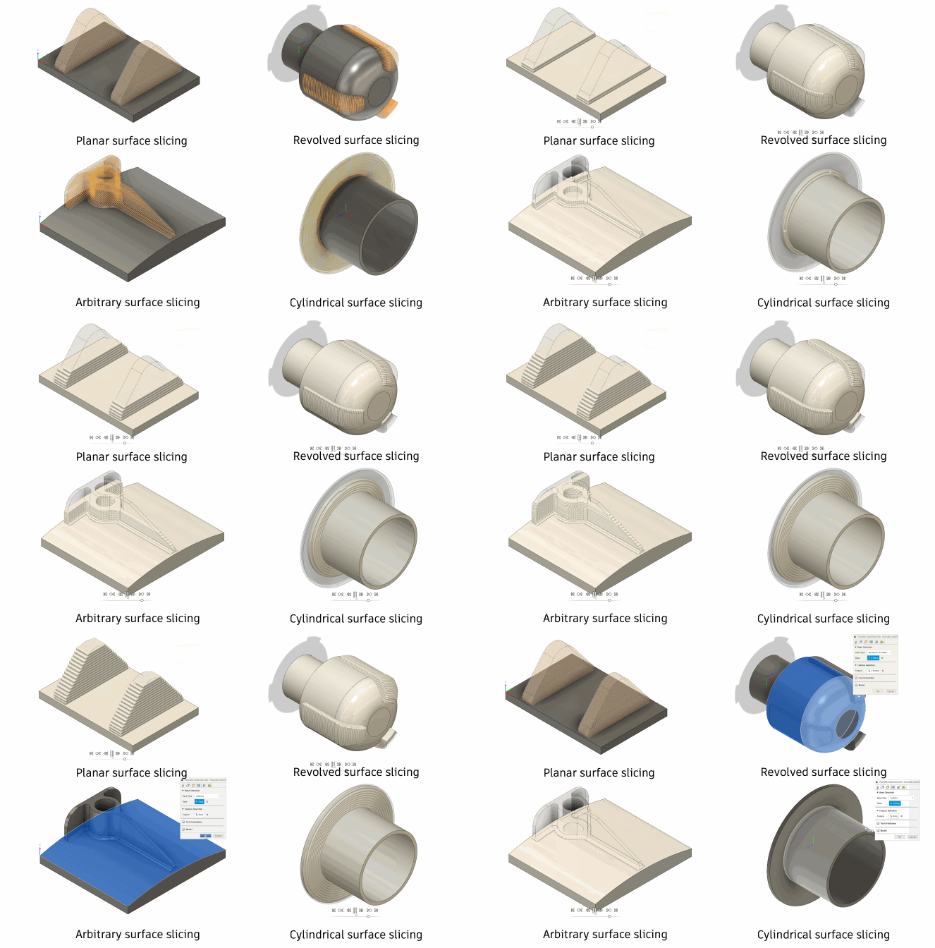
Additive multi axis deposition toolpaths, used to drive additive manufacturing processes such as Directed Energy Deposition and multi axis polymer deposition are being graduated from preview to the additive build extension. What these toolpaths enable you to do is drive multi-axis additive manufacturing machines, including metal processes such as directed energy deposition as well as polymer and concrete deposition processes. To access these toolpaths, you will need to subscribe to the additive build extension.
Learning more about the Multi-Axis Feature Construction strategy.
API
Manufacturing API improvements
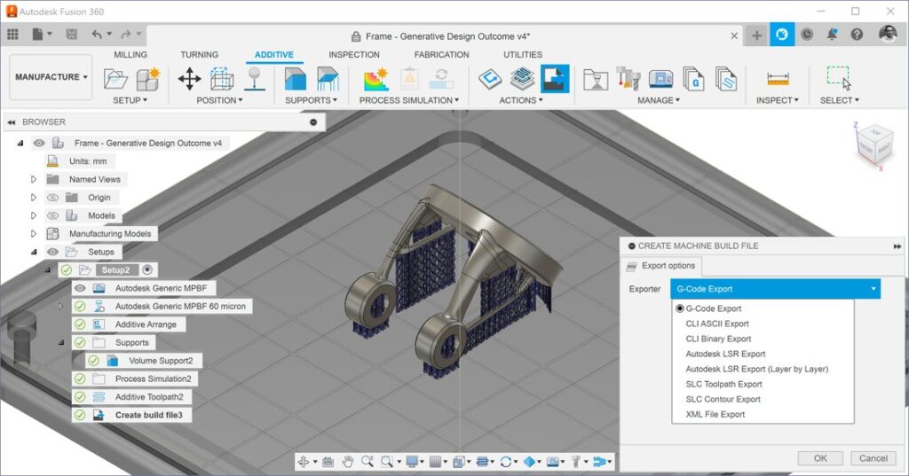
After generating the toolpath for an additive setup, you can now generate additive manufacturing machine files associated with our 3D printer (example: Gcode, CLI, SLC, MTT, …) via the API for all relevant machine types. If your setup includes a Print setting for a Metal Powder Bed Fusion 3d printer with multiple Machine export options, you can now select your specific export type to use during the file generation via the API.
Customer Reported Fixes
Upcoming Events

We’re back, baby! Registration is open for Autodesk University 2023, happening November 13-15 in Las Vegas, Nevada.
For three decades, AU has been at the heart of the Design and Make industries. It brings together innovators in architecture, engineering, construction, product design, manufacturing, and media and entertainment, to share ideas, advance industry practices, and explore opportunities for the future. It’s the conference for those who make anything. At AU this year you’ll find everything from fun classes and hands on labs to interactive experiences and community meet ups.
Looking for fun Fusion 360 specific classes and events to add to your schedule? Check out these blog posts for some ideas on where to get started:
Well, what are you waiting for? Register today.
What’s Coming Next
Get a sneak peek at what’s to come in the 2023 Fusion 360 Roadmap and an understanding of the “why” behind the features we’re investing in.
DISCLAIMER: Roadmaps are plans, not promises. We’re as excited as you to see new functionality make it into the products, but the development, releases, and timing of any features or functionality remain at our sole discretion. The projects mentioned in this roadmap are highlights and do not account for ongoing efforts like bug fixes, platform, and service maintenance. These roadmap updates should not be used to make purchasing decisions.
Become a Fusion 360 Insider

Want to engage more with the Autodesk community, use previews, and test out the latest build one month before it’s released to the general public? Check out the Fusion 360 Insider program! The Autodesk Fusion 360 Insider Program enables you to access the next version of Fusion 360 and all the new features, improvements, and fixes, 3-4 weeks before the general public. As a member, you’ll gain inside knowledge of when we are deploying an update, what’s new, and what’s coming next . You will also have the opportunity to join exclusive events, try pre-release functionality, and give feedback straight to the product teams.