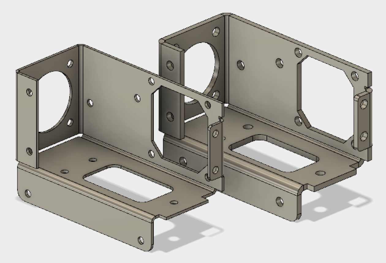
Hello folks, my name is Patrick and I am one of the user experience designers on the Fusion 360 team. We’ve been busy designing and building the sheet metal tools for the upcoming sheet metal experience inside Fusion. This is a follow up on Bryce’s blog post to take a little deeper look at the core workflows we’ll be addressing in the initial release of sheet metal. First off, we’re focusing on supporting workflows for designers and engineers to make sheet metal parts; because if you can’t model your sheet metal parts, you can’t manufacture it (a little hyperbolic, I know). We’re going to look into how we handle properties, our one flange to rule them all approach and cutting across bends. We understand you sheet metal-heads out there know there is a lot that goes into sheet metal designs (material thickness, k factors, minimum bend radius, bend reliefs, flanges, flat patterns, rips, hems, punches, DXF output..). So where do you start developing workflows? Well, we are starting at the beginning.
 Properties are the root of how sheet metal designs behave: thickness, bend radius, k factor, relief shapes, etc. We’re calling these “sheet metal rules” in Fusion 360. Our intention is to provide you a simple way to build your library by providing you with a handful of “starter” rules you can copy, edit and save to your library. For folks that don’t have a ton of experience with sheet metal properties the rules will be a simple way to get started. For those of you who do possess a plethora of experience, the ability to dial in your rules to your particular design process will be supported. Also the library syncs with your profile just like preferences so wherever you login, you’ll have access to your library. Select a rule from your library when a sheet metal component is created and all the properties from that rule are applied. We’re hoping this keeps your nose out of the Engineer’s Handbook looking up material k factors, bend reliefs, bend radii every time you start a design.
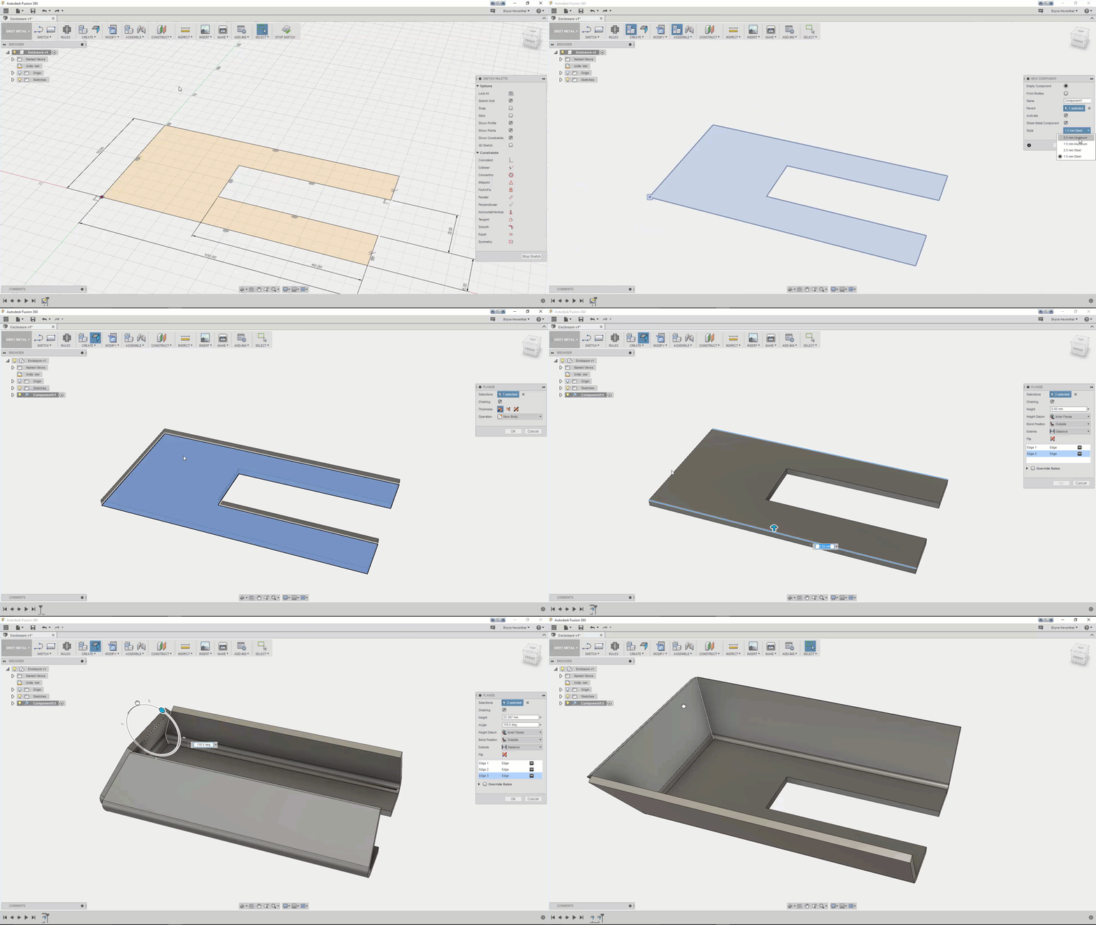
 A large part of sheet metal design is creating flanges. As Bryce points out, we’ve simplified this by combining what is typically multiple commands. We took the philosophical approach of a flange is a flange is a flange; that the different types of flanges in other systems are really hyper specialized flavors of one another. We wanted to simplify this; giving those of you new to sheet metal less stuff to be overwhelmed by and provide a robust enough tool for the experienced designer. The type of flange that is created is determined by the geometry you select. The intent is to allow you to create a flange, right-click and repeat, create another flange and repeat to your hearts content. If you are new to sheet metal design, we hope this shortens the learning curve and gets you up and running quickly. For the seasoned sheet metal designer, the thought is this reduces the number of commands you need to think about. You won’t have to decide which flange command you need to use in what situation.
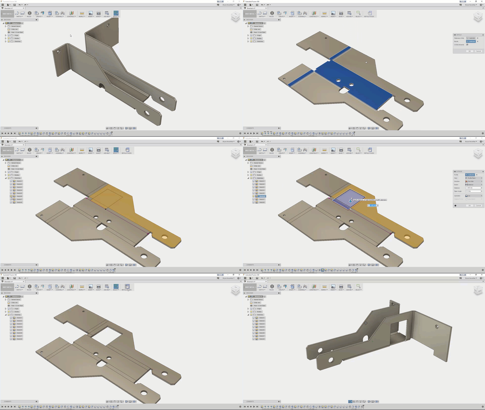
 Once you have flanges created, you often need to create cut features across multiple flanges. Other design tools provide an unfold command and Fusion will have something similar. Where Fusion 360 will be different is the unfold command will be a mode similar to sketch or sculpt. So you’ll unfold, create your cuts, then refold. Everything between the unfold and refold will be grouped in the timeline. Keeping the features grouped makes it simple to roll back and update later.
We will also take advantage of Fusion’s frequent update cadence to bring you constant bug fixes, idea station requests, and other over all sheet metal goodness. Our first workflow will address creating press brake designs from scratch. You will be able to create new sheet metal designs as an individual component or within the context of an assembly. Later, we will address importing and recognizing sheet metal components from other CAD software. This lets you import and flatten sheet metal designs even if they were created in another software. We hope this makes it easier to work in a multi-CAD environment or helps transition to Fusion from another software. The third big workflow we’ll get to is converting a solid body to a sheet metal design. Customers have requested the ability to start with a solid box, shell it, then rip the corners and split into multiple components. With Fusion’s top-down design approach, this workflow will be seamless.