Welcome back to our SPICE Simulation Series, Part 2! In this blog, we’ll be running one of the most fundamental simulations in Autodesk EAGLE 8.4, DC operating point analysis. This method will allow you to analyze the behavior of a circuit when a DC voltage or current is applied. In our example project, we’ll be verifying the expected current from a voltage source to ground. This simulation might sound simple on the outside, but it’s a great way to learn the basics of how SPICE simulation works in EAGLE. Let’s try it out!
Our Example Project
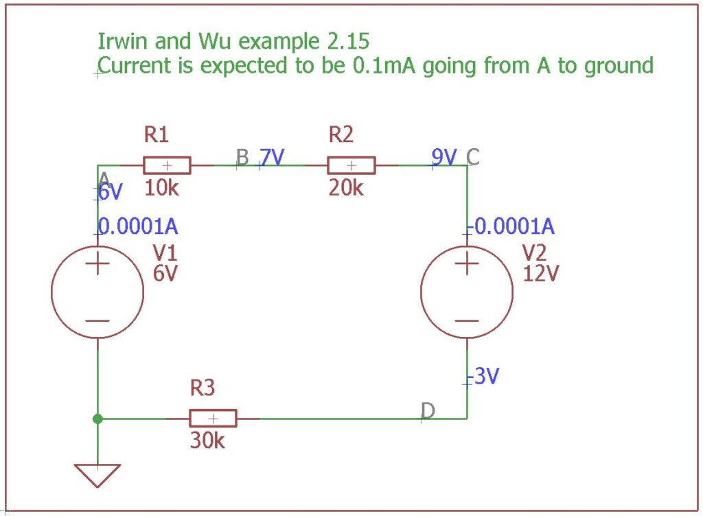
The SPICE simulator in Autodesk EAGLE 8.4 comes with a ton of pre-configured designs. Each design is set up for a specific simulation type. For our operating point analysis, we’ll be working with a primary circuit taken from a popular undergraduate textbook as shown below:
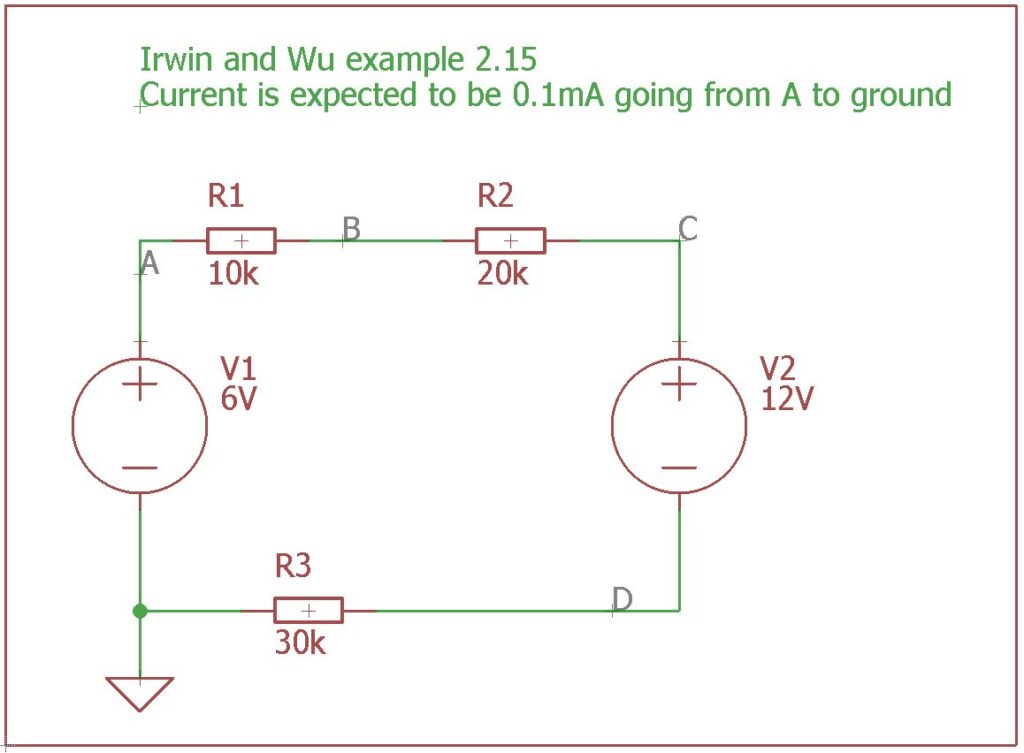
This circuit is typically used in basic circuit design classes to teach students how to calculate currents and voltages. It features two voltage sources and three resistors. We want to confirm that our current is 0.1 mA as it travels through node A to ground.
To open this example project, look for the KVL project folder within the Project » ngspice directory in your Autodesk EAGLE control panel.
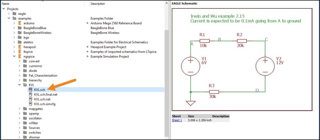
As we mentioned, this project is already set up for SPICE simulation, but what does that mean? It means that all of the schematic symbols are already SPICE enabled or have SPICE models attached to them. Without these models, the circuit would not be simulatable. There’s no visual difference between a part that is SPICE simulation ready and one that isn’t on your schematic. To determine if your symbol is SPICE compatible, you can do the following:
- Right-click the schematic symbol and select Properties.
- In the Properties dialog look at the value in the Library field.
- Select OK to close the dialog.
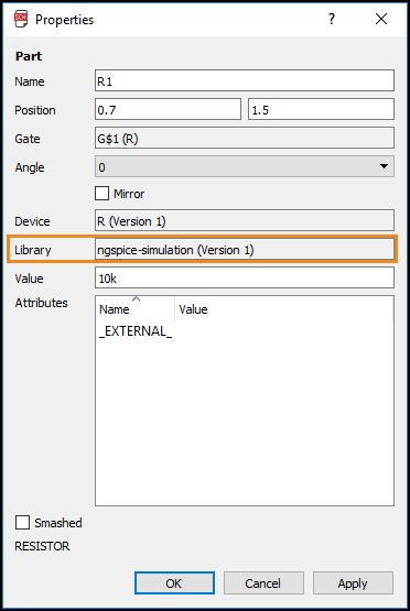
Here we can see that this part is from the ngspice simulation library. This is a managed online library that ships with Autodesk EAGLE 8.4 which contains other pre-configured SPICE parts.
One thing to keep in mind is that if you make your own SPICE compatible parts, this library value will be different when viewing a symbol’s properties. However, when working with preconfigured parts, the ngspice-simulation library is an indicator that your symbol is simulation ready.
The Simulation Dialog
Every SPICE simulation is run from the Simulation dialog in Autodesk EAGLE 8.4. You can open this in one of two ways. Either select the Simulation at the top of your interface or enter “sim” in the command line and press Enter. You’ll notice four tabs when you open the simulation dialog, let’s walk through each before running our operating point analysis.
Configuration Tab
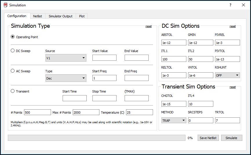
The first tab is where you’ll set the simulation type. The left-hand side contains all of the available simulation options. Operating Point is selected by default since that’s what our design is configured for. However, if you open another ngspice example project, another simulation type will be the selected default.
On the right, you have your DC Sim and Transient Sim options. You likely won’t ever need to change these values unless your simulation runs into converging or timestamp issues. These and other common SPICE related issues can be resolved by tweaking the DC sim and Transient Sim options. For example, turning on RSHUNT is a conventional method to help a troublesome circuit converge.
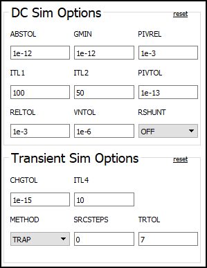
For this walkthrough we’ll leave all these values at default. If you change one by mistake just press reset to start fresh.
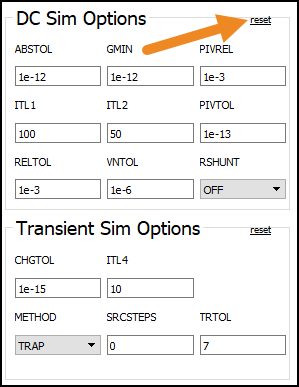
An essential button on this tab is the Save Netlist button. Whenever you make a change to a symbol value or name on your schematic, pressing this button will update your SPICE netlist configuration. There’s also the Simulate button, which we’ll be working with later.
Netlist Tab
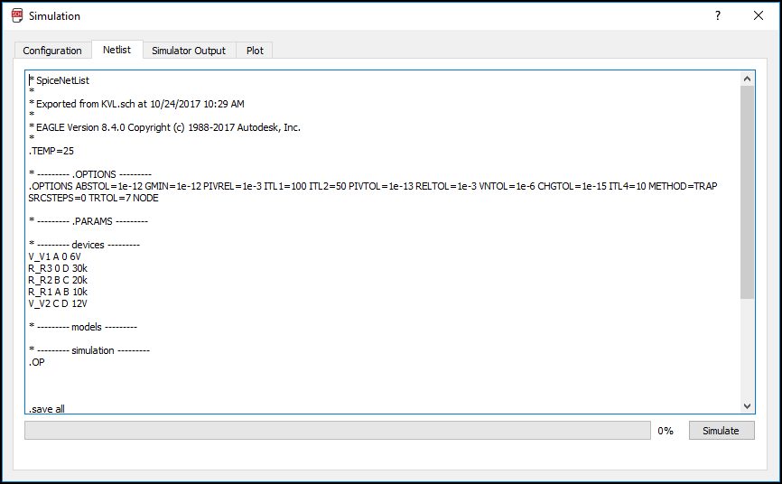
The Netlist tab displays a raw text format of your netlist configuration, which includes your simulation settings, devices, models, and more. The netlist is a text-based representation of your visual schematic. If you change values here, it won’t change anything on your schematic.
Under the Options heading are all of the values that you set in the Configuration tab. You can also change these values directly here if you’d prefer.
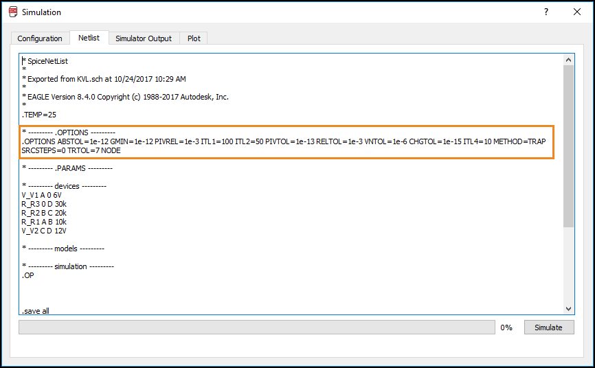
Look under the Devices heading, and you’ll see all of the parts connected in your schematic.
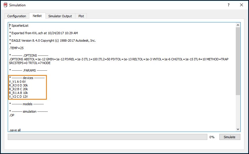
The format goes like this:
Component Type, Reference Designator, Net/Pin Connections, Symbol Value
For example,
R_R1 A B 10k
This device is a resistor, R, with reference designator R1, pins connected to nets A and B, with a resistance value of 10k.
You can quickly copy and paste information to/from your netlist and also make quick changes to parameters. For example, we could change our R1 resistor to 12k, or our V1 voltage source to 3.5V, and then immediately run our simulation based on this edited netlist. This is a great option if you want to quickly test values and compare results without having to change your schematic.
One important note, when you select the Save Netlist button on your Configuration tab this will recreate the netlist with parameters from your schematic. Use this button if you ever tweak values and want to revert to your default netlist values.
Simulator Output & Plot Tabs
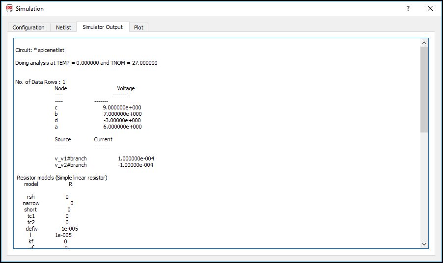
These last two tabs are where all of your simulation outputs will display. Raw text results will display in the Simulator Output tab, and the Plot tab will provide a visual graph for transient analysis methods.
Since our operating point analysis is only measuring values at a single point in time results will only be displayed in the Simulator Output tab.
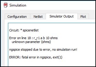
The Simulator Output tab is also where you can see any errors with your simulation. This tab is important to review for simulation specific errors. For example, changing the value on a symbol might work for EAGLE, but not the SPICE simulator. When a simulation is run, EAGLE will check all of your component values and alert you about any simulation errors. Here’s an example below:
Running an Operating Point Analysis
Let’s now run your first operating point analysis simulation with the following steps:
- Open the KVL.sch example from the Project » ngspice folder in the Autodesk EAGLE Control Panel.
- Select the Simulation icon to open the Simulation dialog.
- Operating Point should be selected as the default Simulation Type, with # of points set to 500, and temperature set to 25.
- Select the Simulate button to run your operating point analysis.
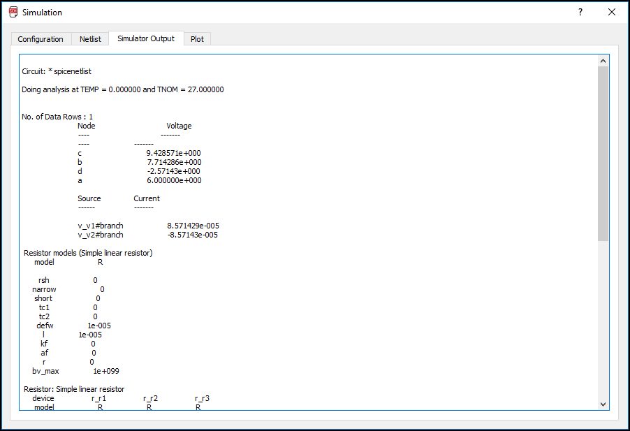
When the simulation completes, you’ll be taken to the Simulator Output tab. Here you can see a breakdown of the voltage and current as it travels through each node in the circuit.
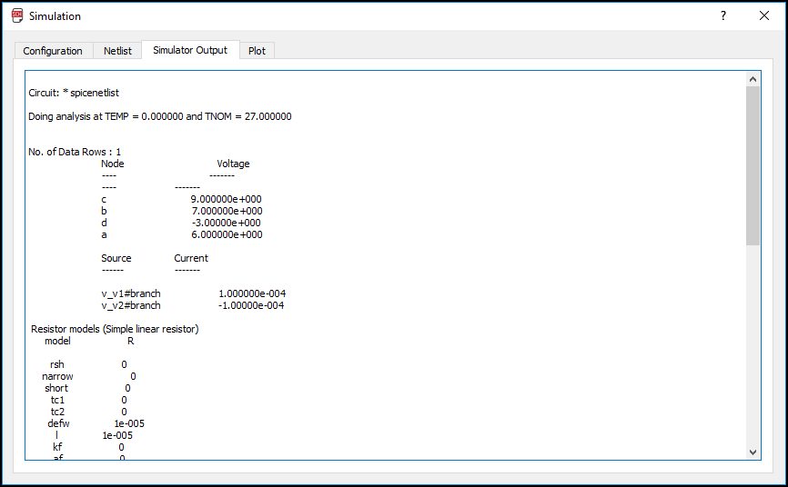
If you close the Simulation dialog, you’ll also see simulation results displayed on your schematic in blue. Here you can see that we’re getting 0.1 mA of current through node A to ground. You can toggle the display of simulation results on your schematic by selecting the OP Results Toggle at the top of your interface.
What if your circuit wasn’t performing as expected? Instead of changing symbol values and going through the whole process again, you can quickly run a simulation by changing values in your netlist. Here’s how:
- In the Simulation dialog, select the Netlist tab.
- Under the Devices heading, change the value of one of the components.
- Select the Simulate button to run your operating point analysis.
Again you’ll be taken to the Simulator Output Tab to analyze your simulation results. Tweaking values in the netlist tab make easy work of finding the right fit for parameter values.
SPICE Made Simple
Operating point analysis is one of many SPICE simulation methods available in Autodesk EAGLE 8.4. If you ever need to analyze the voltage and current of a circuit at a specific point in time, then this is your simulation of choice. Or if you need to inquire about the values of components like MOSFETs, you should run an Operating Point analysis. In future blogs, we’ll be looking at more advanced simulation methods including DC Sweep, AC Sweep, and Transient Analysis. Be on the lookout for more installments in our SPICE Simulation Series soon!
Have you been following along? Try the new SPICE simulation for free! Download Autodesk EAGLE 8.4 now.