Welcome back to our SPICE Simulation Series, Part 4! In Part 3 we showed you the ins and outs of DC Sweep and AC Sweep analysis. Now it’s time to dive into the final simulation type in Autodesk EAGLE – Transient analysis. We’ll also be covering a commonly asked question: how do you map SPICE models to existing components?
Transient Analysis Setup
Transient analysis is pretty simple; it simulates the behavior of your circuit’s voltage and current over a defined period of time. This simulation is perfect for identifying performance issues such as nonlinear distortion, intermodulation, saturation, clipping, and oscillations.
A transient analysis in EAGLE takes three variables, Start Time, Stop Time, and TMAX. TMAX defines the maximum allowed step time and can be useful for analyzing oscillators. The other two settings define when the transient analysis starts and stops.
Example Project
The example project we’ll be working with is an opamp circuit that uses subcircuits and models. Let’s open this now. Look for the opamp project folder within the Projects » ngspice directory in your Autodesk EAGLE Control Panel. Then open opamp1.sch.
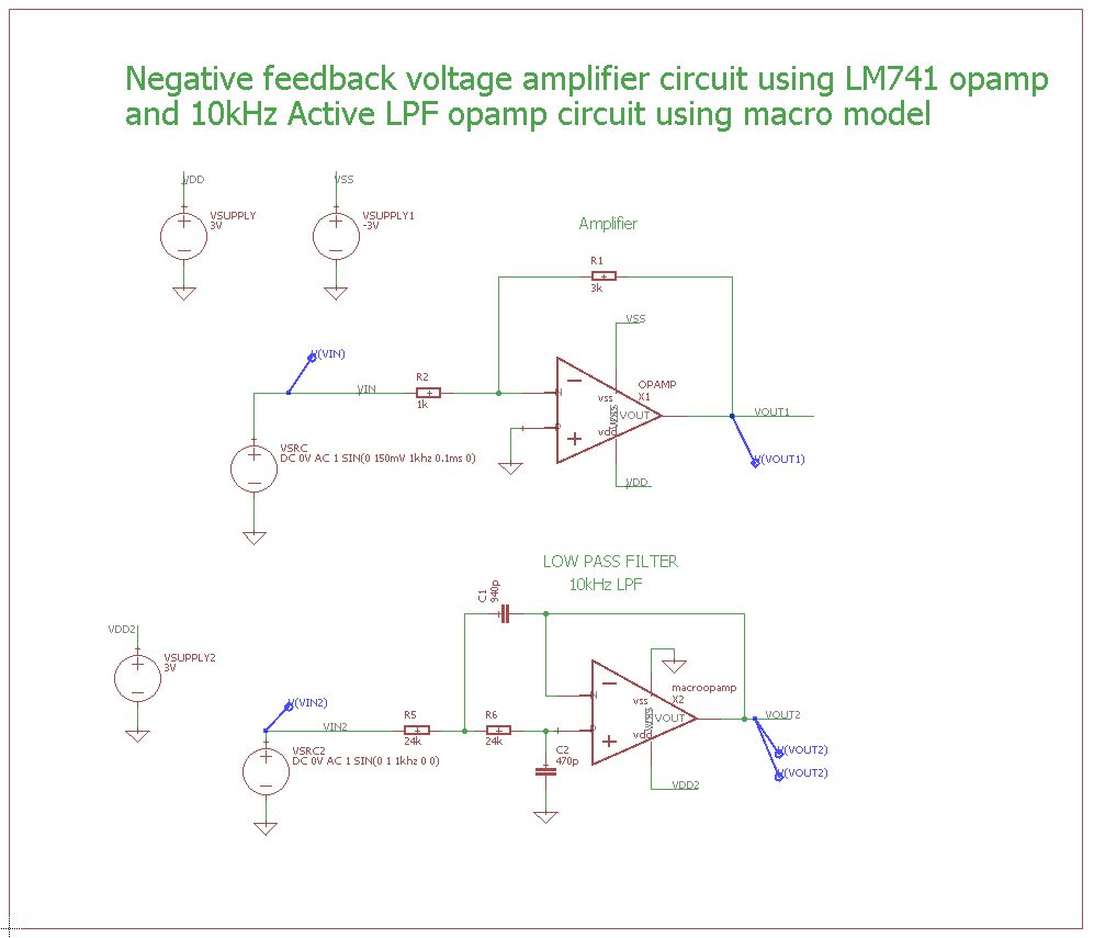
In this example circuit, we have two opamp subcircuits. At the top is our voltage supply with a couple of resistors. This voltage is then fed into the middle circuit where we have a negative feedback amplifier. In the bottom, there’s a filter. What we want to do is look at this circuit in the time domain with transient analysis and see what happens to our voltage and current.
SPICE Models
Let’s talk about SPICE models before running our simulation. When you place a part like an opamp on a schematic, you get a default model called lm741 that’s already mapped to a library. But how do you change this to map to a SPICE model instead?
- First, right click on an opamp symbol and select Add Model.
- In the Add Model dialog select the Map button next to the listed part.
- This will open the Map to Model dialog. Here you can see the loaded model and also the button to load a new model.
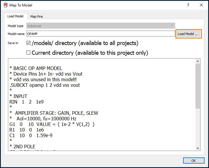
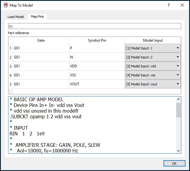
Once a new model gets loaded you’ll be taken to the Map Pins tab to map all of the pins on the symbol to SPICE model inputs. We’re not going to make any changes to our opamp at the moment; we just wanted to show you a quick and easy way to load in a new SPICE model.
Netlist Part Models
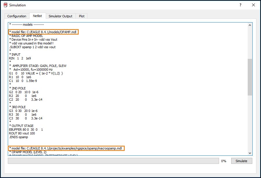
When parts get added to SPICE models, this will be shown in your netlist. Let’s see how this looks. Select the Simulate button at the top of your interface to open the Simulation dialog, then select the Netlist tab.
When SPICE models are added to parts, this will be shown in your netlist. To make it clear where models are coming from, the directory for each model is referenced. Here we can see that we have two opamps, one is located in the directory of our opamp project folder, the other is in the global models directory folder.
EAGLE will make several attempts to locate models for your parts, looking in this order:
- The directory where your schematic is located.
- The global model directory for all default EAGLE models.
- The library where the component resides.
You can use this order of call to your benefit. For example, if you have a part with a model mapped in a library, you can override that model by adding a different model in your project folder. This can be useful if you want to preserve the default EAGLE models library.
Keep in mind, when sharing a schematic design with a fellow designer you’ll need to send both the schematic file and all included SPICE models.
Voltage Source
One last thing before we run our simulation. When setting up voltage sources on your schematic, you’ll often need to tweak their sources to define AC/DC values or transient functions. To do this, right-click one of the voltage sources on your schematic and select Source Setup. This will open the Source Setup dialog.
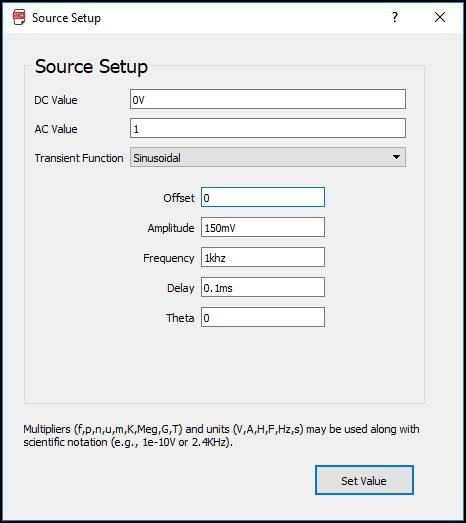
Here you can configure your DC and AC values for your source. For a transient simulation, you might also want to change the value to get an exponential, pulse, or sinusoidal function.
This is a useful dialog all around to set the values for your source parts. We won’t be making any changes to this schematic since it’s already configured, but now you know where to find it.
Running the Simulation
Now that we’ve got the basics covered let’s run our Transient analysis. Follow along with these steps:
- Select the Simulate icon at the top of your interface to open the Simulation dialog.
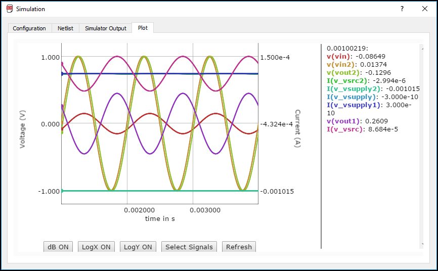
- Select Transient for the Simulation Type. For Start Time enter 1ms, for Stop Time enter 4ms. Leave TMAX blank.
- Select the Simulate button to run the Transient analysis.
In the Plot tab, we can see all of our signals and their change in voltage/current over time. Everything looks normal as expected, let’s move on to part mapping!
Part Mapping
Now we’ll be looking at an example project called mapgates. Let’s open this now. Look for the mapgates project folder within the Projects » ngspice directory in your Autodesk EAGLE Control Panel. Then open MapGates.sch.
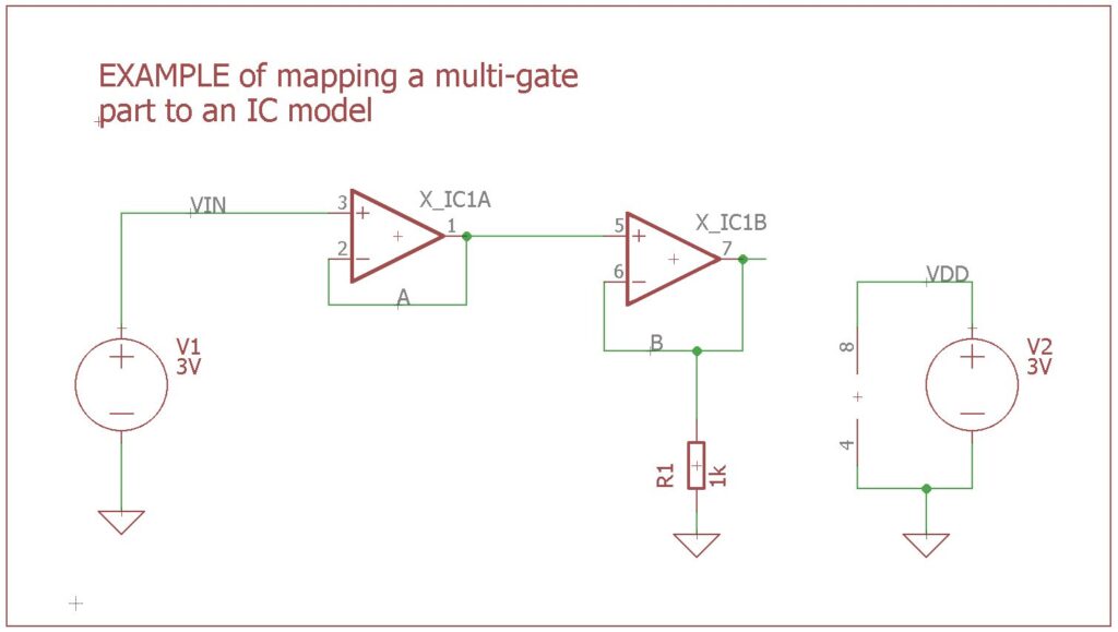
This is an interesting example. Here we have a multigate part which includes a double opamp gate and a gate for power. Let’s see how we can map this multigate part.
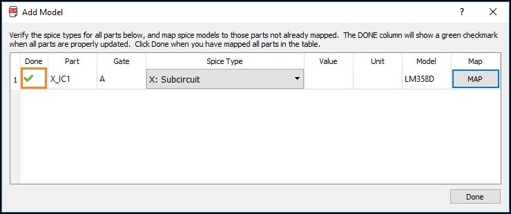
- First, right click the X-IC1A opamp and select Add Model. This will open the Add Model dialog.
- Your first task is to choose the SPICE model type. Since we’re working with an IC that has two opamps and power pins, we’ll select X: Subcircuit as the SPICE type.
- Next, select the Map button to open the Map to Model dialog. Here you can see that we’ve already got an LM385D model attached. This model is a subcircuit with 8 different inputs, which matches the number of pins on the part (3 per opamp gate and 3 for the power gate).
- Select OK to continue to the part mapping process. You’ll get a warning saying that a model file with the same name was found, select Yes to overwrite it.
Now you’re taken to the Map Pins tab. This is where you’ll see all of the gates and pins for your subcircuit and their corresponding model inputs. To map all of the pins to your model you simply have to choose an input that matches with a pin name. If you try to use duplicate model inputs for different pins, you’ll get an error. They all have to be unique.
This is a simple process, pin -IN goes to model in1-, V+ goes to vdd, and so on. Confirm that all of your pins and models match like ours:
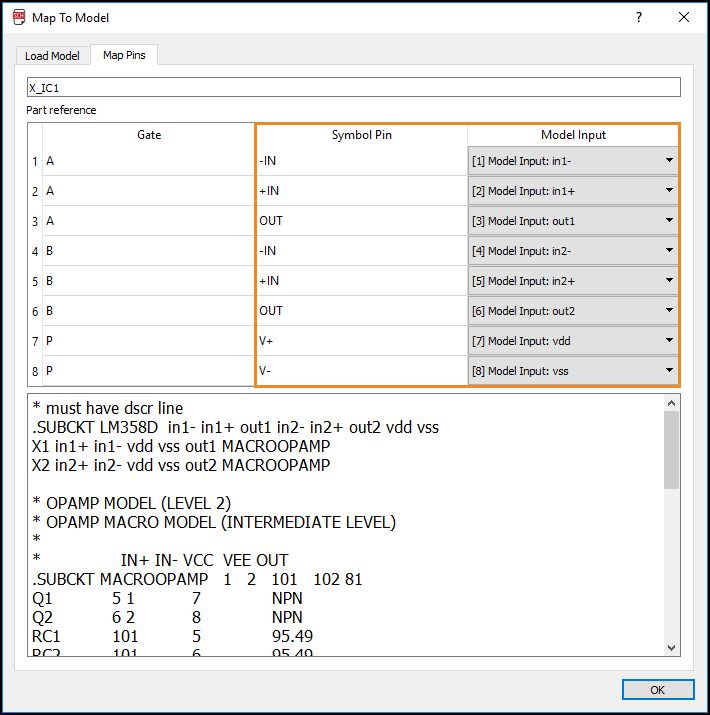
This is a pretty complex example for mapping pins, but the process will always be the same for any part. Unless you’re using a part from the ngspice library, you will always need to map symbol pins to SPICE model inputs as we’ve shown here.
Once all of your model inputs are matched to symbol pins select the OK button. You’ll then be taken back to the Add Model dialog. Here we can see there’s a green checkmark next to our X-IC1 part. This signifies that the part has been successfully mapped a SPICE model, nice job!
The Final Frontier
That covers our SPICE Series, Part 4! Today we learned about the final SPICE simulation method in Autodesk EAGLE, Transient analysis. This method proves an easy way to identify issues with voltage and current performance over a defined period of time. We also looked at how to map SPICE models to existing components.
At this point, we’ve covered all of the basics of SPICE in Autodesk EAGLE, and you now know how to perform all of the simulations. But what happens if you have an existing schematic that needs to be simulated? In a future update, we’ll be showing you how to make it SPICE-compatible, stay tuned!
Have you been following along? Try the new SPICE simulation for free! Download Autodesk EAGLE 8.4 now.