Welcome back to our final SPICE Simulation Series, Part 6! In Part 5 we showed you how to make your existing schematic designs SPICE compatible, but what about your parts? Chances are you have your own libraries that you know and trust. In this blog, we’ll be showing you how to make those libraries SPICE compatible in a few simple steps.
Starting Basic with Intrinsic Devices
We’re going to assume that you already know how to create libraries in Autodesk EAGLE. If you don’t, be sure to check out these past installments to learn how:
Our focus here won’t be on how to create a new library from scratch. Instead, we’ll be showing off the difference for how to make SPICE compatible parts. All this requires is the addition of one final step when you create a new device.
Example Library
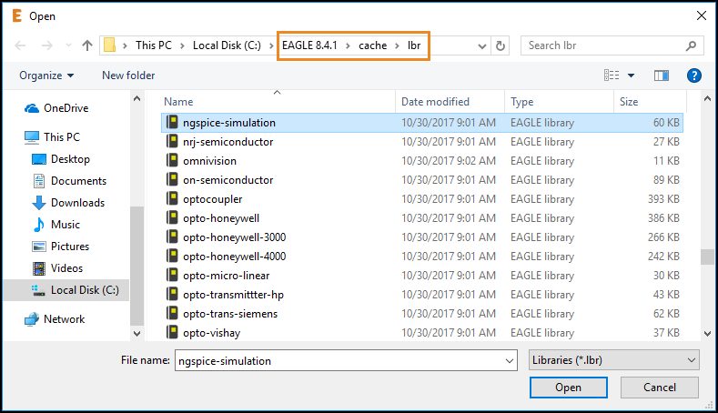
We’re going to run through this tutorial using the existing ngspice simulation library. If you want to follow along open this library now from your Autodesk EAGLE Control Panel. Select File » Open » Library, then open the ngspice-simulation.lbr file. This can be found in the /cache/lbr folder in the Autodesk EAGLE directory.
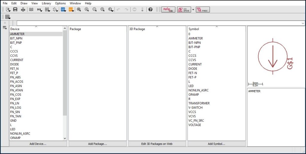
After opening the library file, you’ll be greeted with the Library editor. In a typical workflow, you’ll first create a package and symbol and then link those together with a device. As you can see in this library, we have some pre-populated symbols and devices. Packages aren’t needed since this library is made solely for SPICE simulation.
All of the magic to convert an existing part to a SPICE compatible one happens in the Device editor. Let’s start this process from scratch and pretend that we need to make a new device. Follow along:
In the Library editor select the Add Device button.
In the Add Device dialog enter a new device name, then select OK.
In the Warning dialog select Yes to confirm you want to create a new device.
This will open a new Device editor, which is where we need to do several things including adding a symbol and mapping it to a spice model. Here’s how:
First, select the Add icon on the left-hand side of your interface to open the Add dialog.
Choose the R symbol in the list, select OK, and then left-click to place the resistor symbol in the main window.
Press Escape to get out of symbol placement mode and then select Cancel on the Add dialog to close it.
We now have a symbol added to our device; this is a standard process that you should be used to when making a library. As you can see this symbol already has its gate and value fields added. Let’s make it SPICE compatible with the following steps:
Select the Add Modelicon on the left-hand side of your interface; this will open the Add Model dialog.
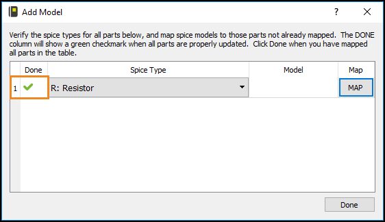
We need to match the Spice Type to the kind of symbol we’re working with. Select R: Resistor in the drop-down options, then select the Map button to continue.
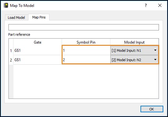
By default, a resistor will come loaded with an Intrinsic Device/No Model. All we need to worry about is mapping the Symbol Pins to the Model Inputs. This is already done for us, so select OK to continue.
Back on the Add Model dialog, you’ll notice a green checkmark has been added next to the listed resistor. Your device is now simulation ready! Save it, and you’re good to go.
Getting Advanced with Loaded Models
The resistor device was super easy to convert to SPICE since it uses the default Intrinsic Device type. However, what happens if you make a device that requires a model? We’ll look at that now.
This time we’re going to make a diode SPICE compatible, which requires the addition of a loaded model. Head on back to your Library editor, make a new device, and you’ll meet us once again in a new Device editor.
Just like before we’ll go through the process of adding a diode symbol to our device
Select the Add icon on the left-hand side of your interface to open the Add dialog.
Choose the DIODE symbol in the list, select OK, and then left-click to place the diode symbol in the main window.
Press Escape to get out of symbol placement mode and then select Cancel on the Add dialog to close it.
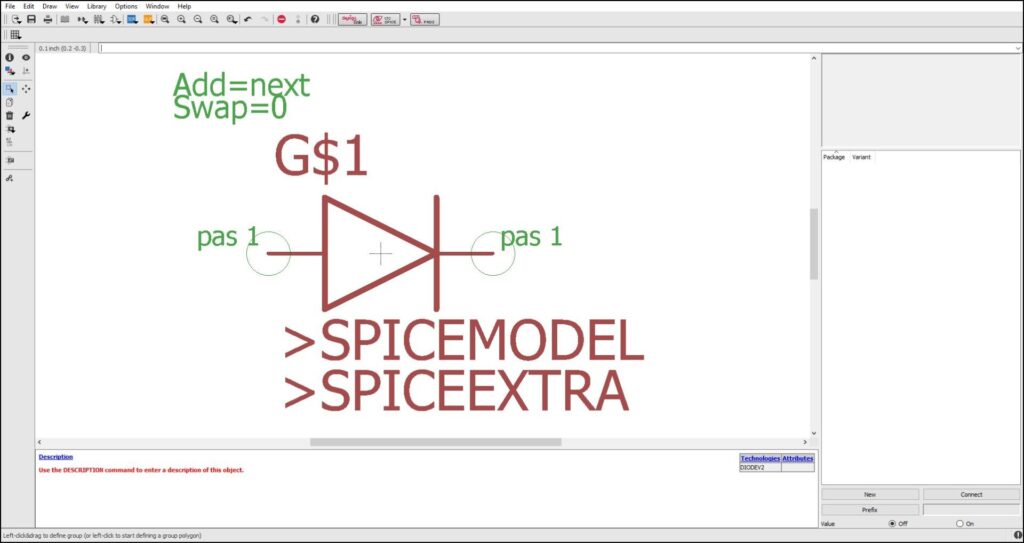
Now we have our diode symbol added to our device, with a similar gate and value as our resistor example. This process has been identical up until now. Let’s look at the differences when mapping it to a SPICE model:
Select the Add Modelicon on the left-hand side of your interface to open the Add Model dialog.
For the Spice, Type choose D: Diode and then select the Map button to continue.
Here’s where things look a little different. When working with our resistor it took us to the Map Pins tab first, but for a diode, we have some settings to configure the Load Model tab.
Loading the Model
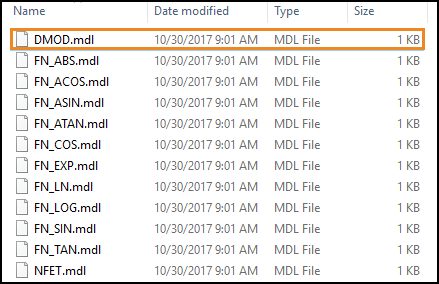
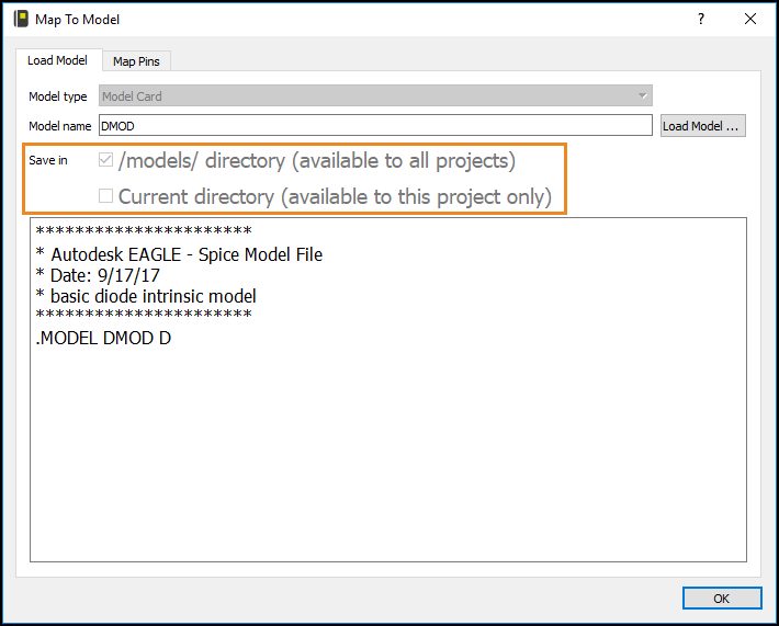
By selecting the Load Model button, you can load a model saved locally on your computer. In this example, we can use one of the EAGLE default models. Look in the /models folder within the EAGLE directory and select the DMOD.mdl file.
Saving the Model
The second setting to configure is where to save this particular model. There is no need to save this model in any location as it will be saved within the library. Once your model is loaded select the OK button to continue.
Mapping the Model
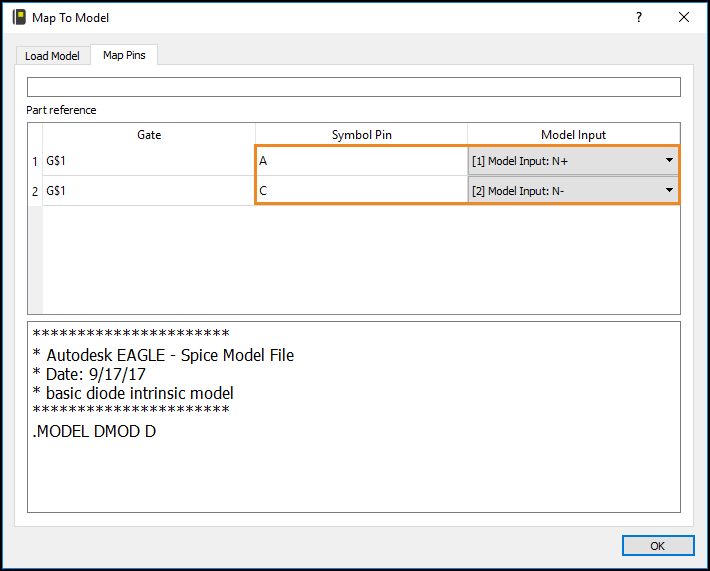
Now we need to map our Symbol Pins to the correct Model Input. EAGLE might have already done this for you. If not, click the OK button at the bottom of the dialog, this will lead you to the Map Pins tab, then change Symbol Pin A to link with Model Input: N+, and Symbol Pin C to link with Model Input: N-. Once those are set select OK to finish.
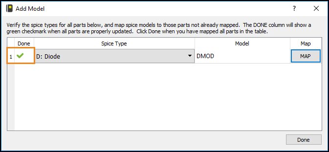
Back on the Add Model dialog, you can see we have our checkmark next to this diode. It’s now simulation ready!
You’re a Part Mapping Pro
All it requires is one extra step to go from a regular library to one that’s simulation ready. Whenever you make a device in the future to be sure to add a SPICE model to it, and then map pins to models to keep your parts future proof. When you place any of these converted devices on your next circuit design, you’ll be able to run your SPICE simulation without any extra work. Remember though, EAGLE ships with a ngspice-simulation library that includes plenty of SPICE compatible parts. Before reinventing the wheel be sure to check this library to see if your device hasn’t already been created.
By clicking subscribe, I agree to receive the Fusion newsletter and acknowledge the Autodesk Privacy Statement.
Success!
______
Cookie preferences
Your privacy is important to us and so is an optimal experience. To help us customize information and build applications, we collect data about your use of this site.
Learn more about the Third-Party Services we use in each category, and how we use the data we collect from you online.
Strictly necessary – required for our site to work and to provide services to you
Qualtrics
We use Qualtrics to let you give us feedback via surveys or online forms. You may be randomly selected to participate in a survey, or you can actively decide to give us feedback. We collect data to better understand what actions you took before filling out a survey. This helps us troubleshoot issues you may have experienced. Qualtrics Privacy Policy
Akamai mPulse
We use Akamai mPulse to collect data about your behavior on our sites. This may include pages you’ve visited, trials you’ve initiated, videos you’ve played, purchases you’ve made, your IP address or device ID, and your Autodesk ID. We use this data to measure our site performance and evaluate the ease of your online experience, so we can enhance our features. We also use advanced analytics methods to optimize your experience with email, customer support, and sales. Akamai mPulse Privacy Policy
Digital River
We use Digital River to collect data about your behavior on our sites. This may include pages you’ve visited, trials you’ve initiated, videos you’ve played, purchases you’ve made, your IP address or device ID, and your Autodesk ID. We use this data to measure our site performance and evaluate the ease of your online experience, so we can enhance our features. We also use advanced analytics methods to optimize your experience with email, customer support, and sales. Digital River Privacy Policy
Dynatrace
We use Dynatrace to collect data about your behavior on our sites. This may include pages you’ve visited, trials you’ve initiated, videos you’ve played, purchases you’ve made, your IP address or device ID, and your Autodesk ID. We use this data to measure our site performance and evaluate the ease of your online experience, so we can enhance our features. We also use advanced analytics methods to optimize your experience with email, customer support, and sales. Dynatrace Privacy Policy
Khoros
We use Khoros to collect data about your behavior on our sites. This may include pages you’ve visited, trials you’ve initiated, videos you’ve played, purchases you’ve made, your IP address or device ID, and your Autodesk ID. We use this data to measure our site performance and evaluate the ease of your online experience, so we can enhance our features. We also use advanced analytics methods to optimize your experience with email, customer support, and sales. Khoros Privacy Policy
Launch Darkly
We use Launch Darkly to collect data about your behavior on our sites. This may include pages you’ve visited, trials you’ve initiated, videos you’ve played, purchases you’ve made, your IP address or device ID, and your Autodesk ID. We use this data to measure our site performance and evaluate the ease of your online experience, so we can enhance our features. We also use advanced analytics methods to optimize your experience with email, customer support, and sales. Launch Darkly Privacy Policy
New Relic
We use New Relic to collect data about your behavior on our sites. This may include pages you’ve visited, trials you’ve initiated, videos you’ve played, purchases you’ve made, your IP address or device ID, and your Autodesk ID. We use this data to measure our site performance and evaluate the ease of your online experience, so we can enhance our features. We also use advanced analytics methods to optimize your experience with email, customer support, and sales. New Relic Privacy Policy
Salesforce Live Agent
We use Salesforce Live Agent to collect data about your behavior on our sites. This may include pages you’ve visited, trials you’ve initiated, videos you’ve played, purchases you’ve made, your IP address or device ID, and your Autodesk ID. We use this data to measure our site performance and evaluate the ease of your online experience, so we can enhance our features. We also use advanced analytics methods to optimize your experience with email, customer support, and sales. Salesforce Live Agent Privacy Policy
Wistia
We use Wistia to collect data about your behavior on our sites. This may include pages you’ve visited, trials you’ve initiated, videos you’ve played, purchases you’ve made, your IP address or device ID, and your Autodesk ID. We use this data to measure our site performance and evaluate the ease of your online experience, so we can enhance our features. We also use advanced analytics methods to optimize your experience with email, customer support, and sales. Wistia Privacy Policy
Tealium
We use Tealium to collect data about your behavior on our sites. This may include pages you’ve visited, trials you’ve initiated, videos you’ve played, purchases you’ve made, and your IP address or device ID. We use this data to measure our site performance and evaluate the ease of your online experience, so we can enhance our features. We also use advanced analytics methods to optimize your experience with email, customer support, and sales. Tealium Privacy Policy
Upsellit
We use Upsellit to collect data about your behavior on our sites. This may include pages you’ve visited, trials you’ve initiated, videos you’ve played, purchases you’ve made, and your IP address or device ID. We use this data to measure our site performance and evaluate the ease of your online experience, so we can enhance our features. We also use advanced analytics methods to optimize your experience with email, customer support, and sales. Upsellit Privacy Policy
CJ Affiliates
We use CJ Affiliates to collect data about your behavior on our sites. This may include pages you’ve visited, trials you’ve initiated, videos you’ve played, purchases you’ve made, and your IP address or device ID. We use this data to measure our site performance and evaluate the ease of your online experience, so we can enhance our features. We also use advanced analytics methods to optimize your experience with email, customer support, and sales. CJ Affiliates Privacy Policy
Commission Factory
We use Commission Factory to collect data about your behavior on our sites. This may include pages you’ve visited, trials you’ve initiated, videos you’ve played, purchases you’ve made, and your IP address or device ID. We use this data to measure our site performance and evaluate the ease of your online experience, so we can enhance our features. We also use advanced analytics methods to optimize your experience with email, customer support, and sales. Commission Factory Privacy Policy
Google Analytics (Strictly Necessary)
We use Google Analytics (Strictly Necessary) to collect data about your behavior on our sites. This may include pages you’ve visited, trials you’ve initiated, videos you’ve played, purchases you’ve made, your IP address or device ID, and your Autodesk ID. We use this data to measure our site performance and evaluate the ease of your online experience, so we can enhance our features. We also use advanced analytics methods to optimize your experience with email, customer support, and sales. Google Analytics (Strictly Necessary) Privacy Policy
Typepad Stats
We use Typepad Stats to collect data about your behaviour on our sites. This may include pages you’ve visited. We use this data to measure our site performance and evaluate the ease of your online experience, so we can enhance our platform to provide the most relevant content. This allows us to enhance your overall user experience. Typepad Stats Privacy Policy
Geo Targetly
We use Geo Targetly to direct website visitors to the most appropriate web page and/or serve tailored content based on their location. Geo Targetly uses the IP address of a website visitor to determine the approximate location of the visitor’s device. This helps ensure that the visitor views content in their (most likely) local language.Geo Targetly Privacy Policy
SpeedCurve
We use SpeedCurve to monitor and measure the performance of your website experience by measuring web page load times as well as the responsiveness of subsequent elements such as images, scripts, and text.SpeedCurve Privacy Policy
Qualified
Qualified is the Autodesk Live Chat agent platform. This platform provides services to allow our customers to communicate in real-time with Autodesk support. We may collect unique ID for specific browser sessions during a chat. Qualified Privacy Policy
Improve your experience – allows us to show you what is relevant to you
Google Optimize
We use Google Optimize to test new features on our sites and customize your experience of these features. To do this, we collect behavioral data while you’re on our sites. This data may include pages you’ve visited, trials you’ve initiated, videos you’ve played, purchases you’ve made, your IP address or device ID, your Autodesk ID, and others. You may experience a different version of our sites based on feature testing, or view personalized content based on your visitor attributes. Google Optimize Privacy Policy
ClickTale
We use ClickTale to better understand where you may encounter difficulties with our sites. We use session recording to help us see how you interact with our sites, including any elements on our pages. Your Personally Identifiable Information is masked and is not collected. ClickTale Privacy Policy
OneSignal
We use OneSignal to deploy digital advertising on sites supported by OneSignal. Ads are based on both OneSignal data and behavioral data that we collect while you’re on our sites. The data we collect may include pages you’ve visited, trials you’ve initiated, videos you’ve played, purchases you’ve made, and your IP address or device ID. This information may be combined with data that OneSignal has collected from you. We use the data that we provide to OneSignal to better customize your digital advertising experience and present you with more relevant ads. OneSignal Privacy Policy
Optimizely
We use Optimizely to test new features on our sites and customize your experience of these features. To do this, we collect behavioral data while you’re on our sites. This data may include pages you’ve visited, trials you’ve initiated, videos you’ve played, purchases you’ve made, your IP address or device ID, your Autodesk ID, and others. You may experience a different version of our sites based on feature testing, or view personalized content based on your visitor attributes. Optimizely Privacy Policy
Amplitude
We use Amplitude to test new features on our sites and customize your experience of these features. To do this, we collect behavioral data while you’re on our sites. This data may include pages you’ve visited, trials you’ve initiated, videos you’ve played, purchases you’ve made, your IP address or device ID, your Autodesk ID, and others. You may experience a different version of our sites based on feature testing, or view personalized content based on your visitor attributes. Amplitude Privacy Policy
Snowplow
We use Snowplow to collect data about your behavior on our sites. This may include pages you’ve visited, trials you’ve initiated, videos you’ve played, purchases you’ve made, your IP address or device ID, and your Autodesk ID. We use this data to measure our site performance and evaluate the ease of your online experience, so we can enhance our features. We also use advanced analytics methods to optimize your experience with email, customer support, and sales. Snowplow Privacy Policy
UserVoice
We use UserVoice to collect data about your behaviour on our sites. This may include pages you’ve visited. We use this data to measure our site performance and evaluate the ease of your online experience, so we can enhance our platform to provide the most relevant content. This allows us to enhance your overall user experience. UserVoice Privacy Policy
Clearbit
Clearbit allows real-time data enrichment to provide a personalized and relevant experience to our customers. The data we collect may include pages you’ve visited, trials you’ve initiated, videos you’ve played, purchases you’ve made, and your IP address or device ID.Clearbit Privacy Policy
YouTube
YouTube is a video sharing platform which allows users to view and share embedded videos on our websites. YouTube provides viewership metrics on video performance. YouTube Privacy Policy
Customize your advertising – permits us to offer targeted advertising to you
Adobe Analytics
We use Adobe Analytics to collect data about your behavior on our sites. This may include pages you’ve visited, trials you’ve initiated, videos you’ve played, purchases you’ve made, your IP address or device ID, and your Autodesk ID. We use this data to measure our site performance and evaluate the ease of your online experience, so we can enhance our features. We also use advanced analytics methods to optimize your experience with email, customer support, and sales. Adobe Analytics Privacy Policy
Google Analytics (Web Analytics)
We use Google Analytics (Web Analytics) to collect data about your behavior on our sites. This may include pages you’ve visited, trials you’ve initiated, videos you’ve played, purchases you’ve made, and your IP address or device ID. We use this data to measure our site performance and evaluate the ease of your online experience, so we can enhance our features. We also use advanced analytics methods to optimize your experience with email, customer support, and sales. Google Analytics (Web Analytics) Privacy Policy
AdWords
We use AdWords to deploy digital advertising on sites supported by AdWords. Ads are based on both AdWords data and behavioral data that we collect while you’re on our sites. The data we collect may include pages you’ve visited, trials you’ve initiated, videos you’ve played, purchases you’ve made, and your IP address or device ID. This information may be combined with data that AdWords has collected from you. We use the data that we provide to AdWords to better customize your digital advertising experience and present you with more relevant ads. AdWords Privacy Policy
Marketo
We use Marketo to send you more timely and relevant email content. To do this, we collect data about your online behavior and your interaction with the emails we send. Data collected may include pages you’ve visited, trials you’ve initiated, videos you’ve played, purchases you’ve made, your IP address or device ID, email open rates, links clicked, and others. We may combine this data with data collected from other sources to offer you improved sales or customer service experiences, as well as more relevant content based on advanced analytics processing. Marketo Privacy Policy
Doubleclick
We use Doubleclick to deploy digital advertising on sites supported by Doubleclick. Ads are based on both Doubleclick data and behavioral data that we collect while you’re on our sites. The data we collect may include pages you’ve visited, trials you’ve initiated, videos you’ve played, purchases you’ve made, and your IP address or device ID. This information may be combined with data that Doubleclick has collected from you. We use the data that we provide to Doubleclick to better customize your digital advertising experience and present you with more relevant ads. Doubleclick Privacy Policy
HubSpot
We use HubSpot to send you more timely and relevant email content. To do this, we collect data about your online behavior and your interaction with the emails we send. Data collected may include pages you’ve visited, trials you’ve initiated, videos you’ve played, purchases you’ve made, your IP address or device ID, email open rates, links clicked, and others. HubSpot Privacy Policy
Twitter
We use Twitter to deploy digital advertising on sites supported by Twitter. Ads are based on both Twitter data and behavioral data that we collect while you’re on our sites. The data we collect may include pages you’ve visited, trials you’ve initiated, videos you’ve played, purchases you’ve made, and your IP address or device ID. This information may be combined with data that Twitter has collected from you. We use the data that we provide to Twitter to better customize your digital advertising experience and present you with more relevant ads. Twitter Privacy Policy
Facebook
We use Facebook to deploy digital advertising on sites supported by Facebook. Ads are based on both Facebook data and behavioral data that we collect while you’re on our sites. The data we collect may include pages you’ve visited, trials you’ve initiated, videos you’ve played, purchases you’ve made, and your IP address or device ID. This information may be combined with data that Facebook has collected from you. We use the data that we provide to Facebook to better customize your digital advertising experience and present you with more relevant ads. Facebook Privacy Policy
LinkedIn
We use LinkedIn to deploy digital advertising on sites supported by LinkedIn. Ads are based on both LinkedIn data and behavioral data that we collect while you’re on our sites. The data we collect may include pages you’ve visited, trials you’ve initiated, videos you’ve played, purchases you’ve made, and your IP address or device ID. This information may be combined with data that LinkedIn has collected from you. We use the data that we provide to LinkedIn to better customize your digital advertising experience and present you with more relevant ads. LinkedIn Privacy Policy
Yahoo! Japan
We use Yahoo! Japan to deploy digital advertising on sites supported by Yahoo! Japan. Ads are based on both Yahoo! Japan data and behavioral data that we collect while you’re on our sites. The data we collect may include pages you’ve visited, trials you’ve initiated, videos you’ve played, purchases you’ve made, and your IP address or device ID. This information may be combined with data that Yahoo! Japan has collected from you. We use the data that we provide to Yahoo! Japan to better customize your digital advertising experience and present you with more relevant ads. Yahoo! Japan Privacy Policy
Naver
We use Naver to deploy digital advertising on sites supported by Naver. Ads are based on both Naver data and behavioral data that we collect while you’re on our sites. The data we collect may include pages you’ve visited, trials you’ve initiated, videos you’ve played, purchases you’ve made, and your IP address or device ID. This information may be combined with data that Naver has collected from you. We use the data that we provide to Naver to better customize your digital advertising experience and present you with more relevant ads. Naver Privacy Policy
Quantcast
We use Quantcast to deploy digital advertising on sites supported by Quantcast. Ads are based on both Quantcast data and behavioral data that we collect while you’re on our sites. The data we collect may include pages you’ve visited, trials you’ve initiated, videos you’ve played, purchases you’ve made, and your IP address or device ID. This information may be combined with data that Quantcast has collected from you. We use the data that we provide to Quantcast to better customize your digital advertising experience and present you with more relevant ads. Quantcast Privacy Policy
Call Tracking
We use Call Tracking to provide customized phone numbers for our campaigns. This gives you faster access to our agents and helps us more accurately evaluate our performance. We may collect data about your behavior on our sites based on the phone number provided. Call Tracking Privacy Policy
Wunderkind
We use Wunderkind to deploy digital advertising on sites supported by Wunderkind. Ads are based on both Wunderkind data and behavioral data that we collect while you’re on our sites. The data we collect may include pages you’ve visited, trials you’ve initiated, videos you’ve played, purchases you’ve made, and your IP address or device ID. This information may be combined with data that Wunderkind has collected from you. We use the data that we provide to Wunderkind to better customize your digital advertising experience and present you with more relevant ads. Wunderkind Privacy Policy
ADC Media
We use ADC Media to deploy digital advertising on sites supported by ADC Media. Ads are based on both ADC Media data and behavioral data that we collect while you’re on our sites. The data we collect may include pages you’ve visited, trials you’ve initiated, videos you’ve played, purchases you’ve made, and your IP address or device ID. This information may be combined with data that ADC Media has collected from you. We use the data that we provide to ADC Media to better customize your digital advertising experience and present you with more relevant ads. ADC Media Privacy Policy
AgrantSEM
We use AgrantSEM to deploy digital advertising on sites supported by AgrantSEM. Ads are based on both AgrantSEM data and behavioral data that we collect while you’re on our sites. The data we collect may include pages you’ve visited, trials you’ve initiated, videos you’ve played, purchases you’ve made, and your IP address or device ID. This information may be combined with data that AgrantSEM has collected from you. We use the data that we provide to AgrantSEM to better customize your digital advertising experience and present you with more relevant ads. AgrantSEM Privacy Policy
Bidtellect
We use Bidtellect to deploy digital advertising on sites supported by Bidtellect. Ads are based on both Bidtellect data and behavioral data that we collect while you’re on our sites. The data we collect may include pages you’ve visited, trials you’ve initiated, videos you’ve played, purchases you’ve made, and your IP address or device ID. This information may be combined with data that Bidtellect has collected from you. We use the data that we provide to Bidtellect to better customize your digital advertising experience and present you with more relevant ads. Bidtellect Privacy Policy
Bing
We use Bing to deploy digital advertising on sites supported by Bing. Ads are based on both Bing data and behavioral data that we collect while you’re on our sites. The data we collect may include pages you’ve visited, trials you’ve initiated, videos you’ve played, purchases you’ve made, and your IP address or device ID. This information may be combined with data that Bing has collected from you. We use the data that we provide to Bing to better customize your digital advertising experience and present you with more relevant ads. Bing Privacy Policy
G2Crowd
We use G2Crowd to deploy digital advertising on sites supported by G2Crowd. Ads are based on both G2Crowd data and behavioral data that we collect while you’re on our sites. The data we collect may include pages you’ve visited, trials you’ve initiated, videos you’ve played, purchases you’ve made, and your IP address or device ID. This information may be combined with data that G2Crowd has collected from you. We use the data that we provide to G2Crowd to better customize your digital advertising experience and present you with more relevant ads. G2Crowd Privacy Policy
NMPI Display
We use NMPI Display to deploy digital advertising on sites supported by NMPI Display. Ads are based on both NMPI Display data and behavioral data that we collect while you’re on our sites. The data we collect may include pages you’ve visited, trials you’ve initiated, videos you’ve played, purchases you’ve made, and your IP address or device ID. This information may be combined with data that NMPI Display has collected from you. We use the data that we provide to NMPI Display to better customize your digital advertising experience and present you with more relevant ads. NMPI Display Privacy Policy
VK
We use VK to deploy digital advertising on sites supported by VK. Ads are based on both VK data and behavioral data that we collect while you’re on our sites. The data we collect may include pages you’ve visited, trials you’ve initiated, videos you’ve played, purchases you’ve made, and your IP address or device ID. This information may be combined with data that VK has collected from you. We use the data that we provide to VK to better customize your digital advertising experience and present you with more relevant ads. VK Privacy Policy
Adobe Target
We use Adobe Target to test new features on our sites and customize your experience of these features. To do this, we collect behavioral data while you’re on our sites. This data may include pages you’ve visited, trials you’ve initiated, videos you’ve played, purchases you’ve made, your IP address or device ID, your Autodesk ID, and others. You may experience a different version of our sites based on feature testing, or view personalized content based on your visitor attributes. Adobe Target Privacy Policy
Google Analytics (Advertising)
We use Google Analytics (Advertising) to deploy digital advertising on sites supported by Google Analytics (Advertising). Ads are based on both Google Analytics (Advertising) data and behavioral data that we collect while you’re on our sites. The data we collect may include pages you’ve visited, trials you’ve initiated, videos you’ve played, purchases you’ve made, and your IP address or device ID. This information may be combined with data that Google Analytics (Advertising) has collected from you. We use the data that we provide to Google Analytics (Advertising) to better customize your digital advertising experience and present you with more relevant ads. Google Analytics (Advertising) Privacy Policy
Trendkite
We use Trendkite to deploy digital advertising on sites supported by Trendkite. Ads are based on both Trendkite data and behavioral data that we collect while you’re on our sites. The data we collect may include pages you’ve visited, trials you’ve initiated, videos you’ve played, purchases you’ve made, and your IP address or device ID. This information may be combined with data that Trendkite has collected from you. We use the data that we provide to Trendkite to better customize your digital advertising experience and present you with more relevant ads. Trendkite Privacy Policy
Hotjar
We use Hotjar to deploy digital advertising on sites supported by Hotjar. Ads are based on both Hotjar data and behavioral data that we collect while you’re on our sites. The data we collect may include pages you’ve visited, trials you’ve initiated, videos you’ve played, purchases you’ve made, and your IP address or device ID. This information may be combined with data that Hotjar has collected from you. We use the data that we provide to Hotjar to better customize your digital advertising experience and present you with more relevant ads. Hotjar Privacy Policy
6 Sense
We use 6 Sense to deploy digital advertising on sites supported by 6 Sense. Ads are based on both 6 Sense data and behavioral data that we collect while you’re on our sites. The data we collect may include pages you’ve visited, trials you’ve initiated, videos you’ve played, purchases you’ve made, and your IP address or device ID. This information may be combined with data that 6 Sense has collected from you. We use the data that we provide to 6 Sense to better customize your digital advertising experience and present you with more relevant ads. 6 Sense Privacy Policy
Terminus
We use Terminus to deploy digital advertising on sites supported by Terminus. Ads are based on both Terminus data and behavioral data that we collect while you’re on our sites. The data we collect may include pages you’ve visited, trials you’ve initiated, videos you’ve played, purchases you’ve made, and your IP address or device ID. This information may be combined with data that Terminus has collected from you. We use the data that we provide to Terminus to better customize your digital advertising experience and present you with more relevant ads. Terminus Privacy Policy
StackAdapt
We use StackAdapt to deploy digital advertising on sites supported by StackAdapt. Ads are based on both StackAdapt data and behavioral data that we collect while you’re on our sites. The data we collect may include pages you’ve visited, trials you’ve initiated, videos you’ve played, purchases you’ve made, and your IP address or device ID. This information may be combined with data that StackAdapt has collected from you. We use the data that we provide to StackAdapt to better customize your digital advertising experience and present you with more relevant ads. StackAdapt Privacy Policy
The Trade Desk
We use The Trade Desk to deploy digital advertising on sites supported by The Trade Desk. Ads are based on both The Trade Desk data and behavioral data that we collect while you’re on our sites. The data we collect may include pages you’ve visited, trials you’ve initiated, videos you’ve played, purchases you’ve made, and your IP address or device ID. This information may be combined with data that The Trade Desk has collected from you. We use the data that we provide to The Trade Desk to better customize your digital advertising experience and present you with more relevant ads. The Trade Desk Privacy Policy
RollWorks
We use RollWorks to deploy digital advertising on sites supported by RollWorks. Ads are based on both RollWorks data and behavioral data that we collect while you’re on our sites. The data we collect may include pages you’ve visited, trials you’ve initiated, videos you’ve played, purchases you’ve made, and your IP address or device ID. This information may be combined with data that RollWorks has collected from you. We use the data that we provide to RollWorks to better customize your digital advertising experience and present you with more relevant ads. RollWorks Privacy Policy
Are you sure you want a less customized experience?
We can access your data only if you select "yes" for the categories on the previous screen. This lets us tailor our marketing so that it's more relevant for you. You can change your settings at any time by visiting our privacy statement
Your experience. Your choice.
We care about your privacy. The data we collect helps us understand how you use our products, what information you might be interested in, and what we can improve to make your engagement with Autodesk more rewarding.
May we collect and use your data to tailor your experience?
Explore the benefits of a customized experience by managing your privacy settings for this site or visit our Privacy Statement to learn more about your options.