Just picked up Fusion 360 and not sure where to start? You’re in the right place. In this article, you’ll learn design basics in Fusion 360 — from opening an empty design to making a basic model. Let’s jump in!
How To Start a New Design
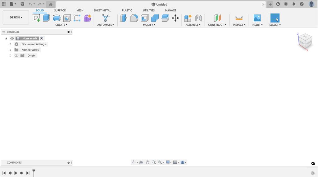
Welcome to Fusion 360! Upon launching the software, you’ll see a blank slate. This area is a new, untitled design file in the Modeling workspace.
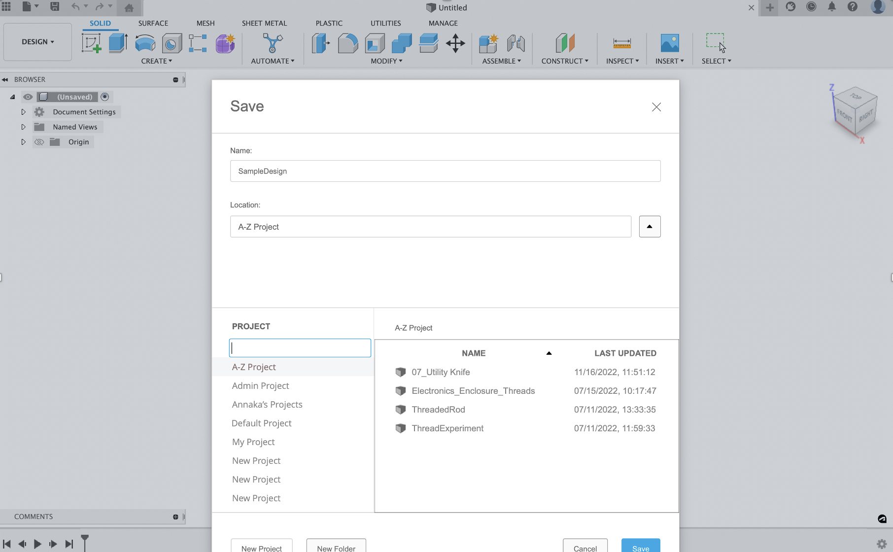
The first thing to do when starting a new design is to save. Hit the Save icon in the left-hand corner of your window. This will open a pop-up window where you can select a name for your file and a location within your projects.
How To Create Basic Bodies
There are two ways to create basic bodies within Fusion 360. The first is creating from a sketch, and the second is creating from primitive shapes within the Command menu.
Not sure which one to choose? If your goal is to create a parametric design, sketches are the superior choice. They are 100% parametric and can be positioned relative to other geometry, projected geometry, etc.
If you’re in a rush and want to ideate quickly by making simple shapes, using the primitives within the command menu if your way to go. Before you decide which is right for you, let’s dive into how these commands work.
Option 1: Creating from Sketch
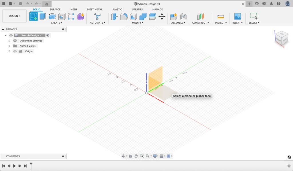
Creating from sketch is easy. First, head over to the Sketch icon on the left-hand side of the toolbar, then select the plane you would like to model on.
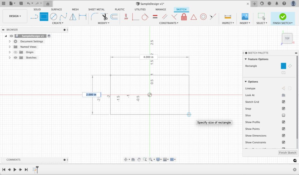
After selecting a plane, you’ll enter the Sketch environment. From there you can create the blueprints for your design.
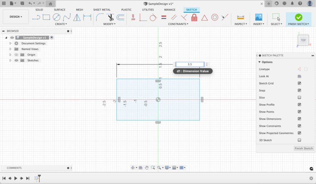
Let’s start by making a rectangle. First, select the two-point rectangle tool on the left-hand side of the toolbar. Then create a rectangle by clicking a start point for the corner of the rectangle and an endpoint for the opposite corner of the rectangle. You can specify the area of your rectangle by either dragging and clicking the location you want the corners to occupy or specifying a value within the value dialog box.
If you want to edit these dimensions later, you can do so by using the Sketch Dimension command. The Sketch Dimension command creates dimensions to define and constrain geometry in the active sketch. Use dimensions to control the size and position of sketch geometry. You can access this tool within the create menu or by using the hotkey “D.” Once the tool is open, select the sketch curves to dimension, then click to place the dimension in the canvas.
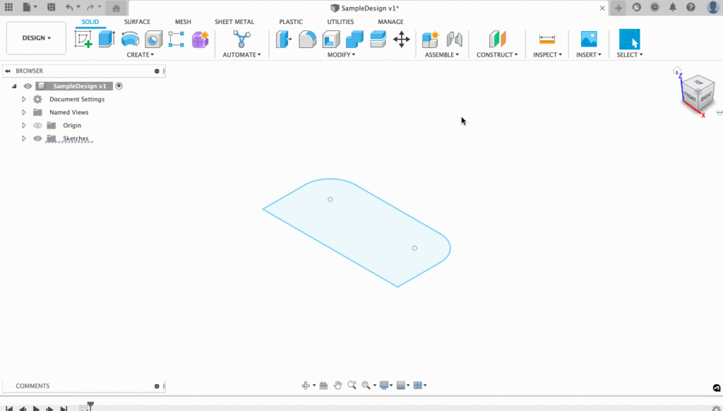
These sketches are easily modifiable to suit your needs. Need to fillet your corners? Use the filter tool found within the Modify section of your toolbar by selecting the tool and then selecting the intersection you want to fillet.
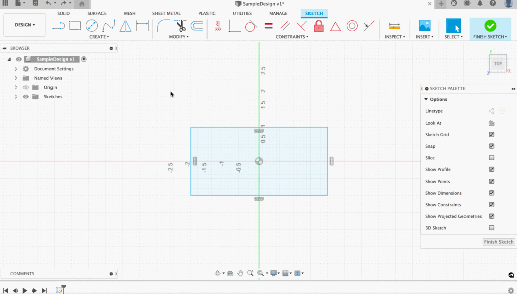
Once complete, hit Finish Sketch and extrude to the height you would like your model to be. Viola! You’ve got yourself a basic body.
Want to learn about how to edit Sketch Dimensions? Check out this article.
Option 2: Creating From the Create Menu

If you’re in a rush and want to quickly ideate using simple shapes, try using the basic shape commands found in the Create menu (box, cylinder, sphere, and coil). Using these commands is simple. Let’s start with an example.
To create a box, click on the Box command. Then select the bottom (XZ) plane and pick two points to define the corners of a rectangle. You can specify a height by entering a value in the dialog box or by dragging the manipulator arrow. You can use the values shown in the dialog or use your own values. For this example, we’ll use a height of .5 in. Once you’re done, click OK to complete the box.
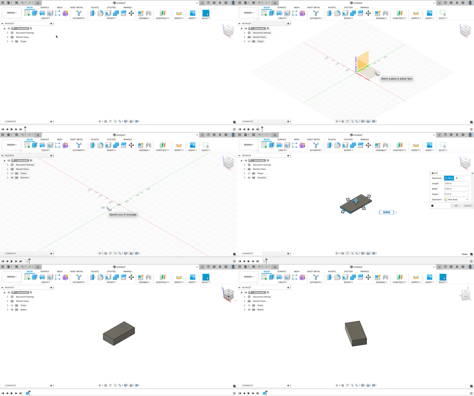
When complete, try modifying the box using different basic shape commands. You can use these commands to create new bodies, add geometry to a body, or cut away material from your model. Let’s try using the Cylinder command to add material to the box we just created.
First, click on the Cylinder command in the Create menu. Then select the top face of the box to position the cylinder on the correct plane. Once you select the plane, move the cursor to the midpoint of the top edge and click to specify the center of the cylinder. Finally, click one of the corners to specify the diameter.
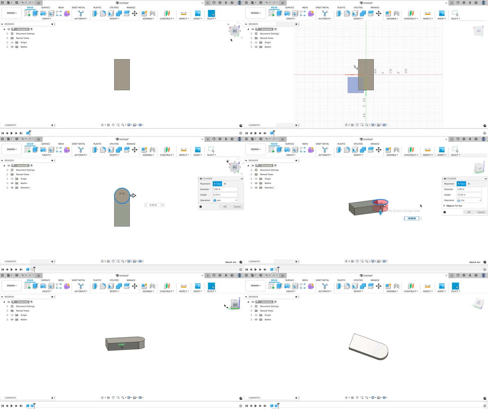
From there you can choose how you would like the Cylinder to modify your existing body. For our example, we are going to enter -.5 in. into our value dialog box to match our box height and change the operation to Join to add material to the body, and then click OK. We now have a brand-new shape! How cool is that?
How To Create Sculpted Forms
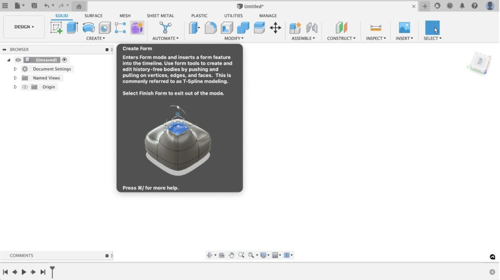
If you’ve never tried out the Form environment, you’re in for a treat. Using T-Splines, you can quickly create organic shapes that would otherwise be difficult to make in the modeling workspace. To start, click the Create Form command on the right side of the create toolbar menu.
The Sculpt workspace has the same simple shapes we saw in the Model workspace, plus a few more. Sculpt also has Extrude, Revolve, Sweep, and Loft for creating bodies using 2D sketches. It’s common to start with a simple shape in the Sculpt workspace.
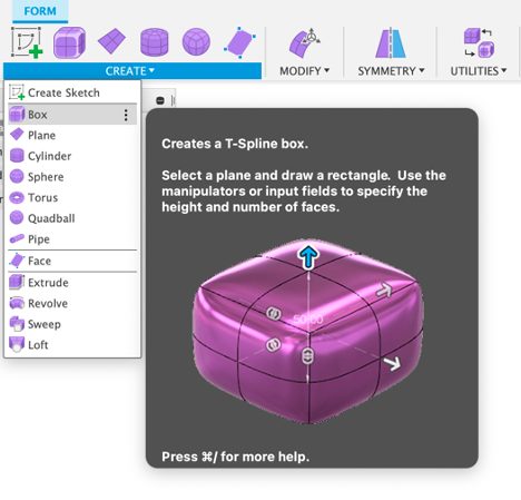
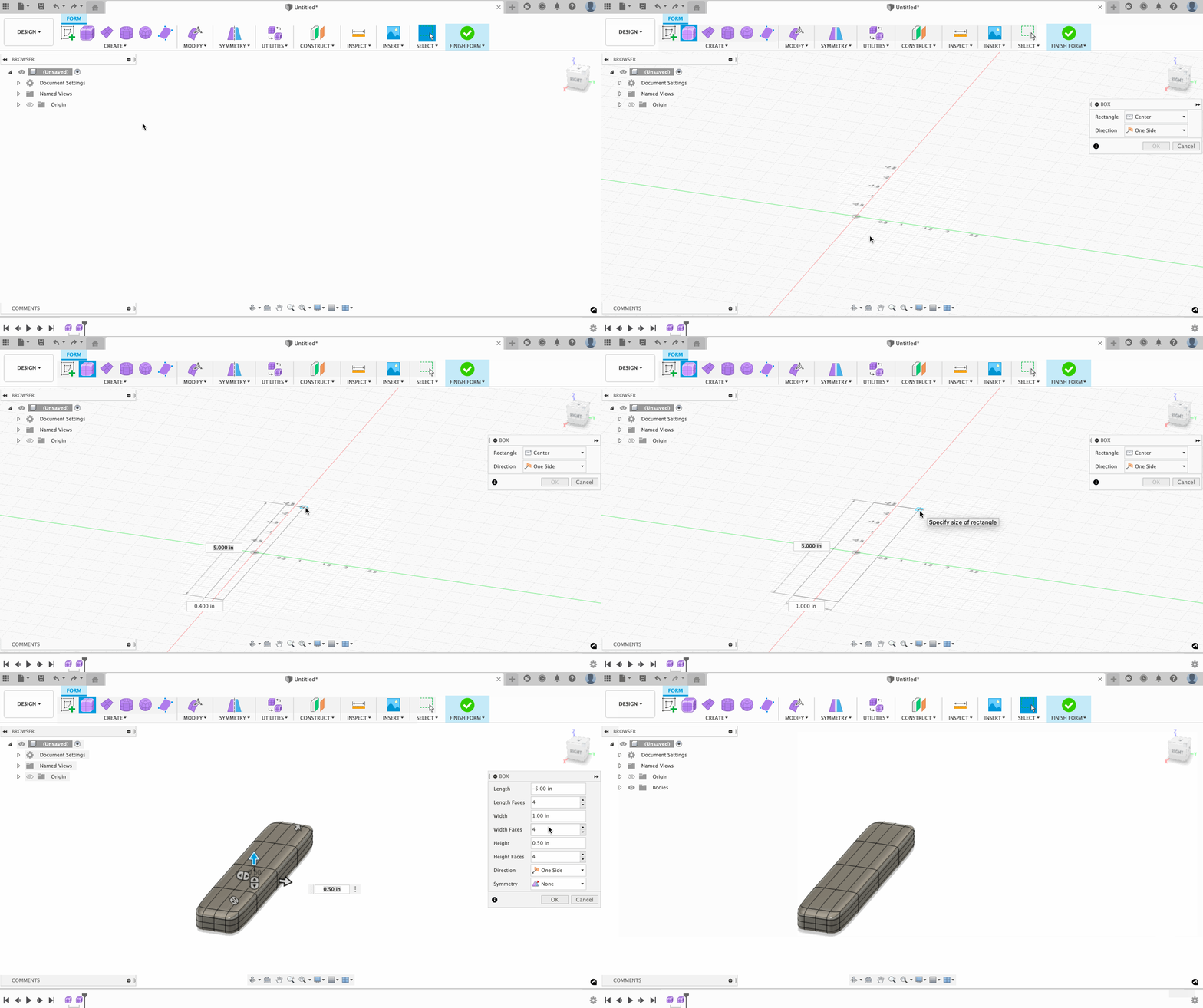
First, click Box in the Create menu. This will take you to the Center rectangle command, where you be able to select a center for your rectangle and enter dimensions by imputing the values in the dialog box or dragging the modifier arrows. For this example, we are going to make the box 5 in x 1 in.
The number of faces on your model’s body determines the control you have over the shape. You want to use the minimum number of faces on a body to give the desired control. For this example, enter 4 for the Length Faces, Width Faces, and Height faces, then click OK to create the box.
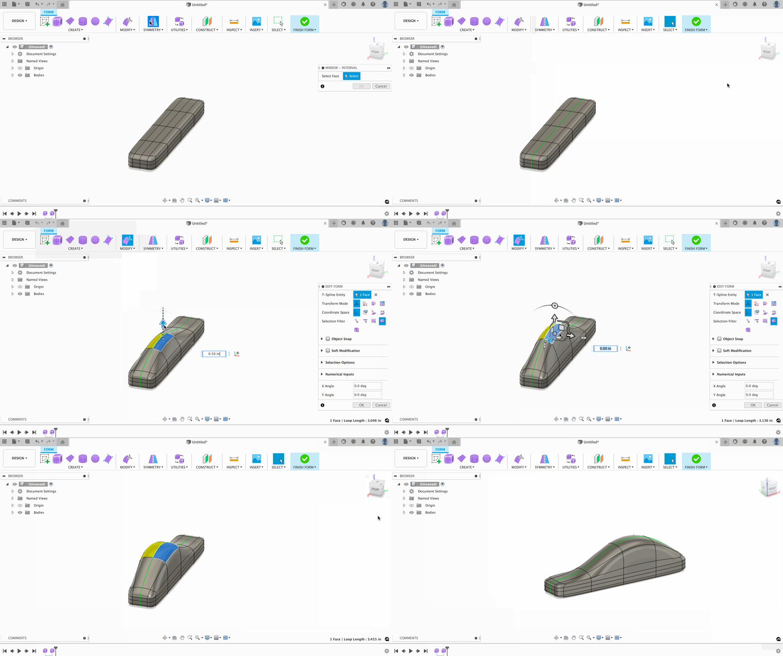
Use the Modify commands to make changes to the bodies in the Sculpt workspace. Click Edit Form in the Modify menu.
If you want to make your design symmetrical, try using the Symmetry tool. To access this tool, click the Icon above Symmetry in the toolbar, this will open the Mirror – Internal command, which will allow you to create a mirror symmetry with the elements of a T-Spline body. To use this tool, select a face on each side of the body. If needed, select edges on each side, then vertices. Once this is complete, modifying one of the selected faces will modify the mirrored face.
Want to learn more about when to use T-Splines? Check out this blog post!
