Safety is always a concern in the back of an engineer’s mind. Even with all the simulations in the world, you still wonder how your PCB will perform under a variety of temperatures, environmental conditions, and handlings in its physical form. This can only be verified with thorough testing. If you’re planning to design PCBs for information technology, audio, video, medical, or appliance applications, then you’ll need to be certified with the utmost safety standards. This means dealing with the details of UL certification. In this blog, we’ll be looking at what UL certification, what kind of standards it requires for PCB designs, and how this certification affects your job as an electronics design.
What is UL?
The Underwriters Laboratory (UL) was founded in 1894 by William Henry Merrill, an American electrical engineer. UL is an independent, international organization that tests products, certifies manufacturers and documents safety standards for a diverse range of industries and applications.

The UL Mark that Underwriters Laboratory offers is a well-known symbol of product safety in the electronics manufacturing industry. There are more than 17 billion UL marks added to new products every year, and their next mark might be on your board. UL offers a rigorous set of standards that covers risk assessment for electronic products, focusing on both fire protection and electrical safety. Since their founding in 1894, UL has evolved with electronics and electrical technology, offering safety certifications for:
- The first vacuum cleaner, electrical signal system, light shield for moving pictures, and vehicle washer with electric lights in 1909.
- The first automatic washing machine in 1937, which had several safety hazards like water spilling into the motor.
- The first black and white television in 1939. UL went on to work with TV makers in 1953 to produce protective shields and glass laminates to prevent imploding picture tubes.
- The first video game arcade machine, microwave oven, personal computer, and solar collector between 1975 and 1980.
Today, UL is working on advancing safety requirements for lithium-ion batteries through computational modeling, thermal analysis, and advanced testing approaches. They’re also one of the leading certification groups to accelerate safety requirements for electric vehicle batteries.

These days UL has a very intimate relationship with the electronics design industry. There’s a very high chance that somewhere along your career journey you’ll design a product that requires the UL Mark of approval.
Why Should You Care About UL?
Many end product standards now require their PCBs to be built with UL safety standards in mind. The following product categories are just a sample of the applications that UL standards cover:
- IEC 60065: Audio and Video Equipment
- IEC 60960: Information Technology Equipment
- IEC 60601: Medical Equipment
- IEC 61010: Equipment for Laboratory Use
- UL 508: Industrial Control Equipment
All of the applications above must be certified with a UL mark following three standards, UL 796, UL 746, and UL 94. These are broken down into specific sub-categories, which includes:
PCB Standard UL 796. This covers printed wiring boards (PWBs) guidelines for standard rigid, metal-based, and high-density interconnect PCBs.
PCB Standard UL 796F. This standard evolved to cover flexible material electronics including flex and rigid-flex PCBs.
PCB Standard UL 746E. This covers all industrial laminates and materials used in the PCB manufacturing process.
PCB Standard UL 746F. This covers all flexible dielectric film materials used in the PCB manufacturing process.
UL 94. This covers all flammability requirements for plastics and PCBs.
As part of UL 796, UL 746 and UL 94 standards, PCBs are thoroughly tested under a number of conditions to evaluate the chances of electrical shock, flammability, and mechanical strength. Here’s an overview of each category and the tests performed:
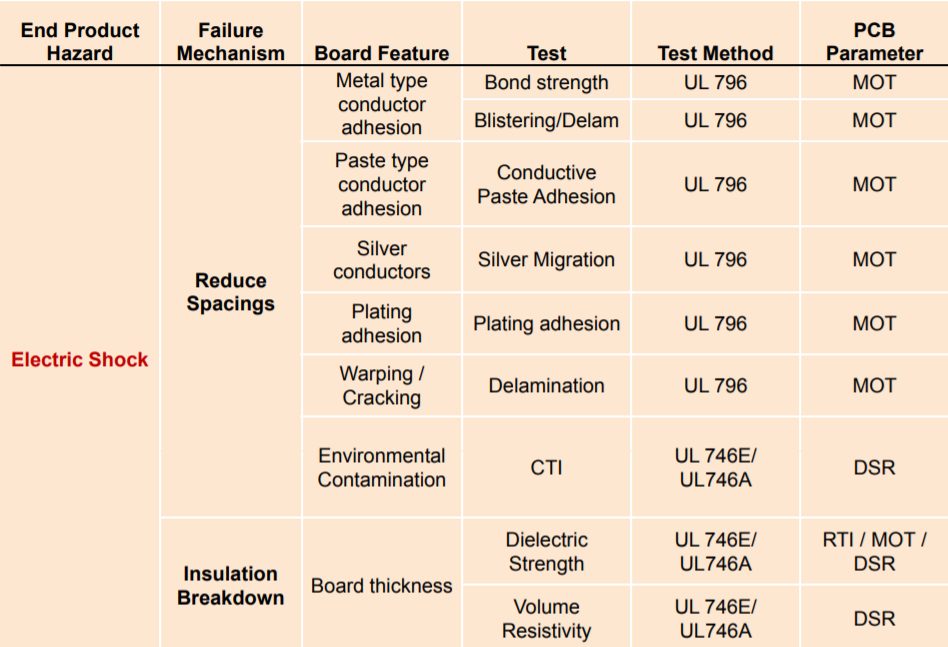
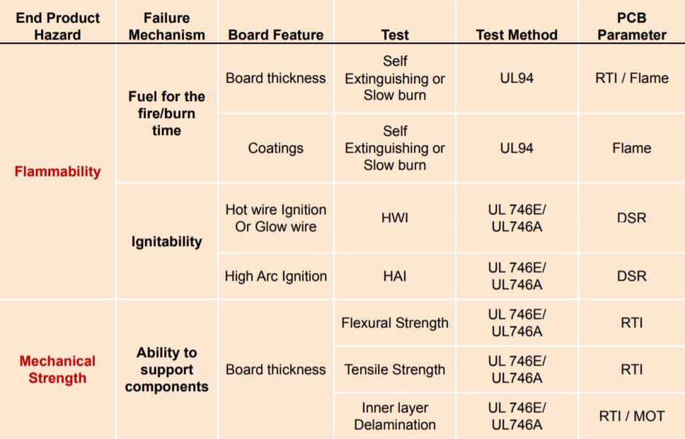
- MOT – Maximum Operating Temperature
- DSR – Direct Support Requirement
- RTI – Relative Thermal Index
Aside from verifying the safety of your electronic device, UL certification also offers other benefits to end users and the industry as a whole, including:
- Reach. UL certified PCBs are recognized globally and can help to extend the reach of your product to new markets.
- Standardization. PCB manufacturers can work from a common set of guidelines to help standardize the fabrication and assembly process.
- Trust. End users and consumers are provided a product that meets a rigorous set of safety standards.
Types of UL PCB Certifications
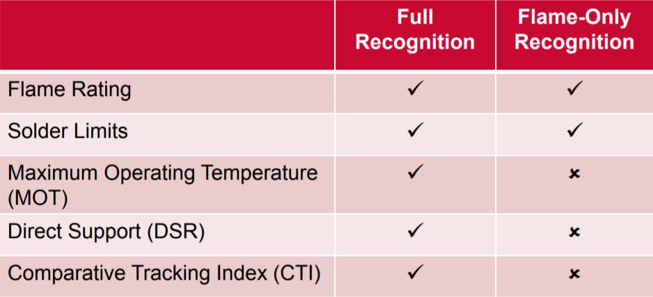
UL certifies PCBs under a PCB Recognition Program that comes in two flavors – Full Recognition and Flame-Only Recognition. These break down to meet the following requirements:
Flame Ratings
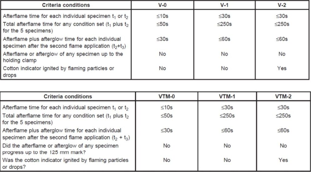
Flame ratings are typically specified by end product requirements and evaluate a sample burn time when a PCB is subjected to a horizontal and vertical flame. These flames are broken down into classes, which includes V-0, V-1, V2, VTM-0, VTM-1, and VTM-2. Details on measured conditions for each class are shown below:
Solder Limits
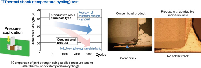
Solder limits test the kind of soldering processes that a PCB will be subjected to during the component assembly process. These tests simulate a thermal shock and maximum temperature to gauge how your PCB performs.
Maximum Operating Temperature
Maximum Operating Temperature (MOT) defines a PCBs maximum continuous use at a specific temperature. This test simulates the exposure of a PCB to normal operating condition temperatures during a 10-56 day period, with temperatures based on your manufacturer’s guidelines.
Direct Support Request
Direct Support Request (DSR) measures the performance of a PCB laminate when in contact with 120V or less. This test is only performed on laminates rather than the whole PCB, and each laminate receives a DSR compliant rating. During this testing, a laminate will undergo several performance tests, including:
- Dielectric strength
- High current arc ignition
- Hot wire ignition
- Volume resistivity
- Heat deflection
Comparative Tracking Index
The Comparative Tracking Index (CTI) also measures the performance of a PCB laminate materials when subjected to a wet contaminant. CTI values are listed as Performance Level Categories (PLC) as shown in the table below:
| CTI range | PLC class |
|
≥ 600 |
0 |
|
400 ➗ 599 | 1 |
| 250 ➗ 399 |
2 |
|
175 ➗ 249 |
3 |
| 100 ➗ 174 |
4 |
| < 100 |
5 |
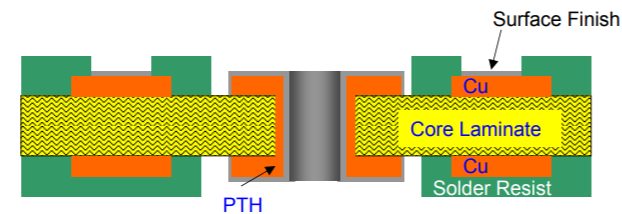
In addition to Full-Recognition and Flame-Only Recognition, PCBs are broken down by category to identify UL-specific requirements based on construction type. These types include:
Single Layer PCBs
| Full Recognition Requirements | Flame-Only Recognition Requirements |
|
|
Multi Layer PCBs
| Full Recognition Requirements | Flame-Only Recognition Requirements |
|
|

Metal Base, Single Layer PCBs
| Full Recognition Requirements | Flame-Only Recognition Requirements |
|
|

Metal Base, Multi Layer PCBs
| Full Recognition Requirements | Flame-Only Recognition Requirements |
|
|

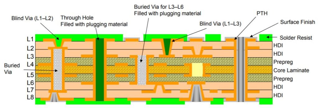
High Density Interconnect PCBs
| Full Recognition Requirements | Flame-Only Recognition Requirements |
| Core Requirements
HDI Requirements
| Core Requirements
HDI Requirements
|
Flexible PCBs
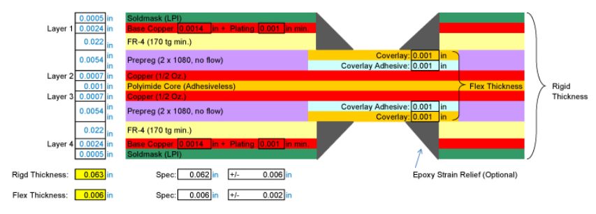
Flexible PCBs are defined by both their application type and construction type. You can reference the above tables for a flexible PCB construction type with the following application parameters:
- Flexible PCBs are tested for dynamic and repeated bending.
- Flex-to-Install PCBs are tested for flexing during installation and field servicing.
- Rigid-Flex PCBs are assessed for a variety of applications, and construction types gave their combination of flexible and rigid circuitry.
What Does the UL Mark Mean On a PCB?
When your PCB receives a UL Mark from your manufacturer, it signifies that your board meets all established safety and flammability requirements. Specifically, a UL Mark signifies that:
- The base material used in your PCB meets a specified flammability level per UL94. For example, when FR4 is subjected to an open flame and then removed it self-extinguishes within 10 seconds and does not drip any flaming particles. Each base material that a manufacturer offers will go through this testing scenario.
- The base material used in your PCB meets the required level of ability to resist ignition from external electrical sources.
- The base material used in your PCB meets the required electrical breakdown value. This is the voltage difference where the insulation properties of a base material may start to break down and cause safety issues.
- The base material in your PCB meets the performance levels for direct support of current carrying capacities as specified in UL 796A.
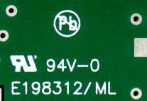
When your PCB receives its UL Mark, it will be printed on your silkscreen layer as shown in the image below. In this example, UL94V-0 signifies that this board meets UL94 flammability requirements at flame class V-0. The E198312 is a unique UL Mark identifier for a specific manufacturer, and ML signifies that this is a Multi-Layer PCB.
How Does UL Affect My Job as a PCB Designer?
UL certification is driven by the end product requirements, and it’s up to you as the PCB designer to know and understand these requirements. We recommend first checking with your end product manufacturer before beginning your design process to determine the specific requirements your PCB must meet. If you are designing any of the UL specified products below then you’ll likely need to get your hands on UL standards documentation:
- UL 60950 – Information Technology Equipment
- UL 60065 – Audio & Video Equipment
- UL 62368 – ITE and Audio/Video Equipment
- UL 60601 – Medical Equipment
- UL 60335 – Appliances
- UL 61010 – Industrial Control Equipment
- UL 8750 – LED Equipment
Once you know your end product rating requirements, it’s time to get started on your design. There are several things to keep in mind when designing a board for UL, including:
Always Select UL Certified Parts
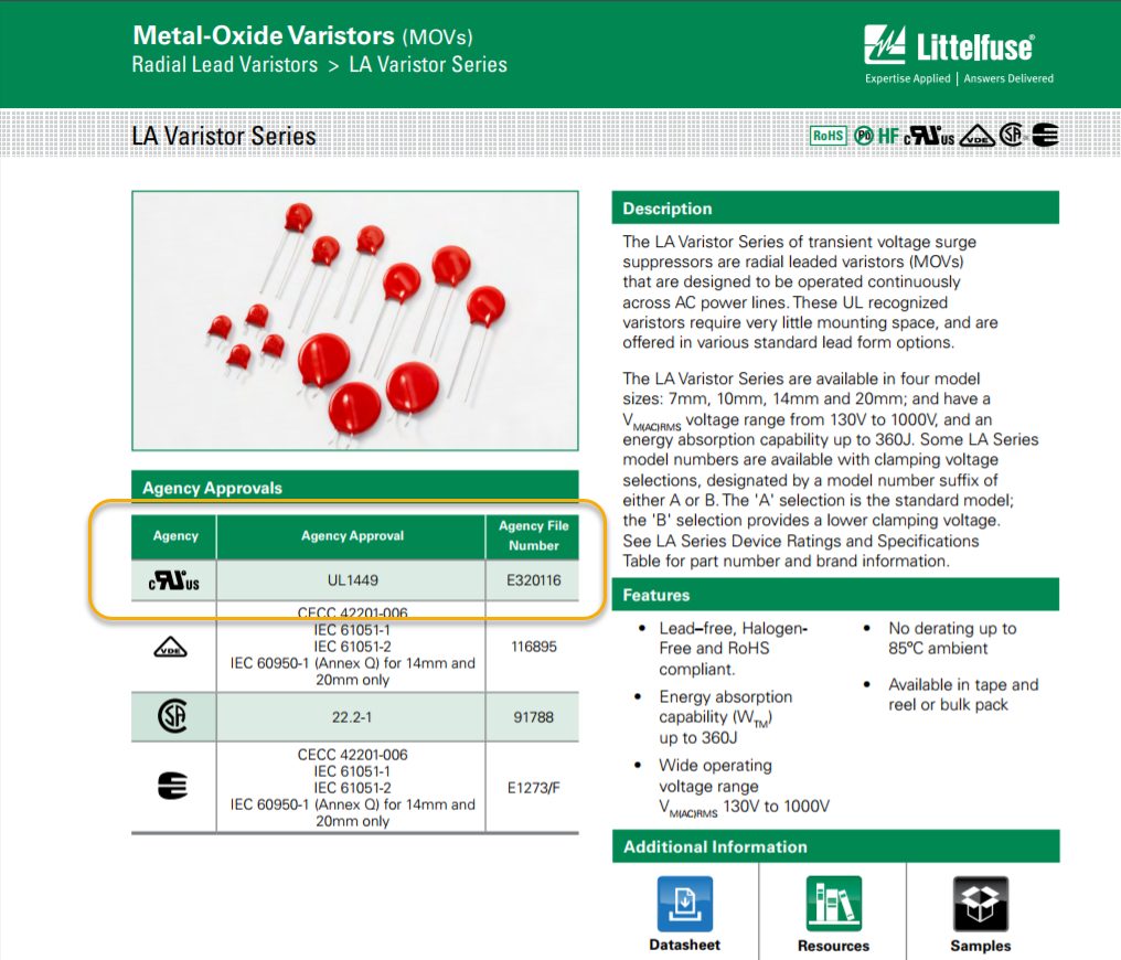
Make sure you always use UL listed parts whenever you have a line voltage present in your design as this will reduce the cost of certification. If you don’t select UL listed parts from your distributor, then someone down the line will have to do the investigation and adjustments. Instead of risking a delay for your project, be sure to look for UL certification marks when putting together your component list. You might need to dig into the datasheet for each component to find the UL approval, as shown for this Metal-Oxide Varistor below:
Follow Clearance and Creepage Distances On Your Board Layout
For high voltage design with operating voltages between 30VAC and 60vDC, you’ll need to pay particular attention to your clearances and creepage when setting up your design rules. There is some confusion between these two rules. Most design tools, including EAGLE, categorize both creepage and clearance rules under a general Clearance category. However, there’s an important distinction to make between both:
Rules for pad-to-pad, pad-to-trace, or trace-to-trace, spacing are considered creepage rules. These rules define the shortest path between two conductive parts.
Rules that define the spacing between two conductive elements measured through the air are considered clearance rules.

Clearance and creepage requirements will be determined by your specific design requirements, and there are no general rules to offer here. Instead, be sure to use this Creepage and Clearance Calculator which meets specifications for UL 60950 and UL 60960-1 among other popular IEC guidelines.
Specify Dielectric Materials for Your Manufacturer
For some end products, UL certification can take weeks or months to secure as your device goes through a series of qualifying tests. Instead of allowing your manufacturer to select any fiberglass material, be sure to specify your dielectric material requires in your design documentation. This will help to avoid any delays in your certification process and costly respins.
Getting Your UL Marking
The good news is that getting a UL Marking on a PCB is a relatively straightforward process. The bulk of UL requirements rest on the shoulders of your manufacturer as part of a UL compliance program. Under this program, your manufacturer is audited for UL compliance four times per year. For manufacturers producing Full Recognition PCBs, random production boards will also be subject to annual testing.
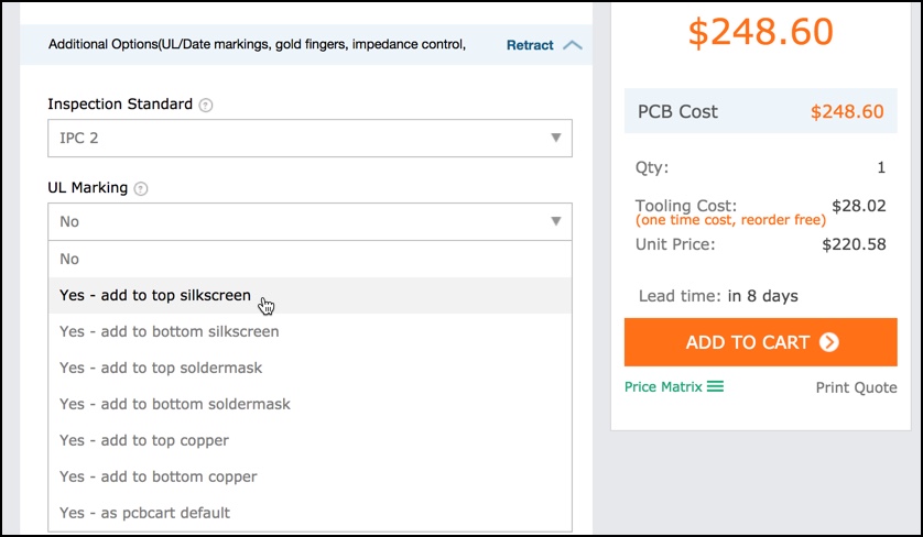
When getting a quote for the fabrication of your PCB most manufacturer websites will have a section where you can select your needs for a UL Marking. In the image below we were able to add a UL Mark through the pcb.cart.com quote tool.
Safety First
Whether you’re designing medical equipment, an IT device, or even a PCB for an appliance, chances are you’ll need to have your board UL certified. The bulk of the certification process is already handled by your manufacturer as they work with UL to test materials and components. However, as a PCB designer, you still need to take the time to research and define the requirements of your circuit board to meet your end product needs. Once your requirements are defined, you’ll need to select UL certified parts during your schematic design and follow creepage and clearance distances on your board layout. Most importantly, when documenting your board, it’s critical to specify the right dielectric material that will meet your end product requirements.
Ready to design your first UL recognized PCB? Subscribe to Autodesk EAGLE today!