This post is also available in: Deutsch (German)
As part of the December 2020 update of Fusion 360, we delivered a hidden gift just in time for the holidays: a new method for generating additive manufacturing outcomes. Internally, we call this project Additive 2.0, and it is part of our Experimental Generative Solvers and Features preview. This new method should go a long way to improve the shape quality and printability of the outcomes compared to what you previously saw in generative design. This was a present I know many of us have been eagerly waiting for, and my team and I would like to “unwrap” everything we delivered.
Using the New Additive 2.0 Algorithm
First off, you must turn on our Experimental Generative Solvers and Features preview from your User Preferences.
With the preview enabled, you will need to turn on Alternative Outcomes in the Study Settings. From there, just set up your study as usual. Enable the additive manufacturing constraint in the Manufacturing Constraints dialog, choose the desired print orientations, and let our solvers take care of the rest.
Once in Explore, for each set of additive outcomes (where a set equals given material and direction), Additive 2.0 will generate the second outcome in each set. Quick tip: the easiest way to see this is to switch to the properties view, isolate down to the additive manufacturing method, and set the Sort By dropdown to Material.
How is Additive 2.0 Better?
Our initial approach to generating additive outcomes left a lot to be desired in shape quality in many scenarios (many of you told us that, and we listened!). It was common to see outcomes with pronounced stair-stepping and other artifacts as we tried to meet overhang requirements and be fully self-supporting. With our new approach, our solvers do a much better job of meeting minimum thickness requirements, balancing design mass, and minimizing support material. This new approach will not sacrifice shape quality to be fully self-supporting.
Let’s dig into a couple of examples that demonstrate how these improvements impact the outcomes we create.
Our first example is the simple generative setup shown below (loads and constraints are hidden). We intend to manufacture this part in the orientation shown in Figure 1 (below), replacing the red obstacle with the build plate.
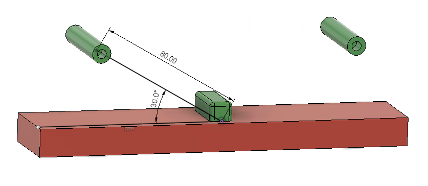
Figure 1 – Design space for v-shaped tension bar example
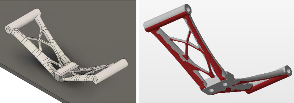
This setup produces an unconstrained outcome, as seen in Figure 2 (below), which is difficult to manufacture for various reasons. First, a large area under the part geometry requires support structures (red highlighted regions in the second half of the figure). Also, the thin features near the center of the part are fragile and may break during support removal. While this design can be additively manufactured, it is far from optimized.
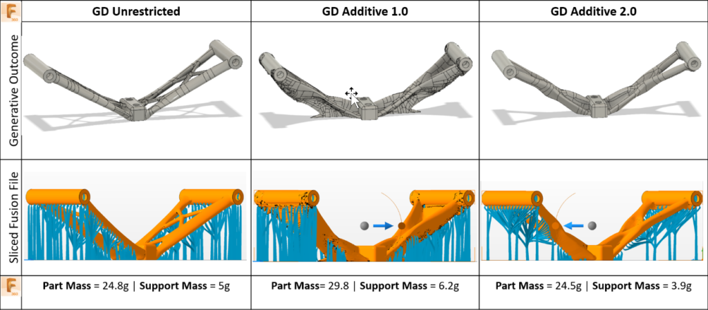
When we start to look at Additive 2.0 side by side with our existing additive constraints (Additive 1.0), the differences become obvious, as shown in Figure 3 (below). In both cases, we configured the additive constraint with an overhang angle of 45 degrees and a minimum thickness of 3mm.
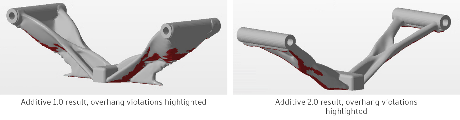
In both cases, the amount of support material required is reduced but not eliminated. However, the Additive 1.0 result, which builds material up from the build plate to support the entire structure, is 50% heavier than the unconstrained outcome. It exhibits stair-stepping artifacts that were a common annoyance with the original additive manufacturing solution. Additive 2.0 also significantly reduces the amount of support material required but does so with subtler changes to the geometry and only increases mass by 11% for this model. Both additive designs satisfy the 3mm minimum feature size, but Additive 2.0 retains a structure much closer to the unrestricted, merging the too-thin lattice beams into a thicker organic structure. The new Additive 2.0 results also eliminate much of the poor surface quality in the original outcome.
In theory, the new Additive 2.0 constraints will reduce supported area and eliminate thin beams with a minimal increase in overall part mass. But are these designs actually more manufacturable? Let’s go through the print preparation process and see.
Validating the Print Process
FFF Example
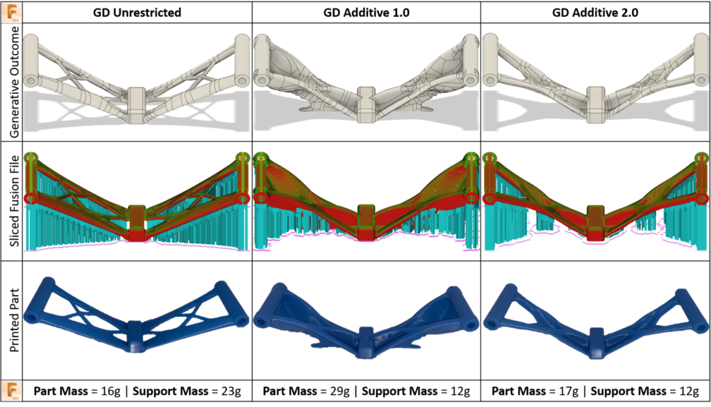
Figure 4 (below) compares the outcomes for Additive 1.0 and Additive 2.0 alongside the original unrestricted result. Each of these results was taken through the generic FFF workflow using the Fusion 360 additive workspace. The models were sliced and post-processed using Fusion 360 before being printed on a desktop FFF machine. Each part was post-processed using the same print settings, machine, and in the same PLA filament. The results shown in Figure 3 clearly identify the improvement between Additive 2.0 and 1.0, with a significant 41.3% reduction in part mass. The benefit of Additive 2.0 compared to utilizing the unrestricted constraints is also highlighted, with a 47.8% reduction of support material required.
SLA Example
Figure 5 (below) compares the outcomes for Additive 1.0 and Additive 2.0 alongside the original unrestricted result prepared for printing in an SLA process. Each of these results was taken through the generic SLA workflow using Netfabb. Similar to the results above, Figure 5 clearly identifies the improvement from Additive 1.0 to 2.0. Both part mass and support material required this process as well.
SLM Example
Let’s look at another, more real-world example. The Motorcycle Triple Clamp example problem in the generative design training materials walks through designing a structural component that connects the fork tubes to the steering stem on a motorcycle. For this example, we want to additively manufacture the component out of aluminum using selective laser melting (SLM).
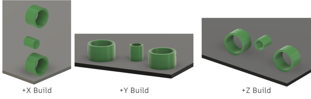
Before running the generative study, we selected the build direction for the component. Build height is a major cost driver, so we avoided the +X direction. We know from experience that we will need to fill in most of the large holes with material during printing and then post-machine to get the tolerance we need. Once the holes are filled in, the +Y orientation will have a rapid change in cross-sectional area at the top face of the part, which causes rapid cooling of a large surface and can cause build issues. As a result, we rejected the +Y orientation and settled on the +Z build direction.
We selected a minimum feature size of 0.25 in (6.35 mm) to ensure that any beams produced are large enough to stand up to the forces from support removal. The overhang angle was set to 45°, consistent with the SLM process’s parameters. The Additive 2.0 outcome is shown in the image below.
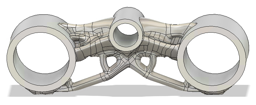
Normally, we would likely make design tweaks to the organic shape at this point and validate design performance. For today, we will skip those steps and go straight to the manufacturing workspace to prepare it for printing.
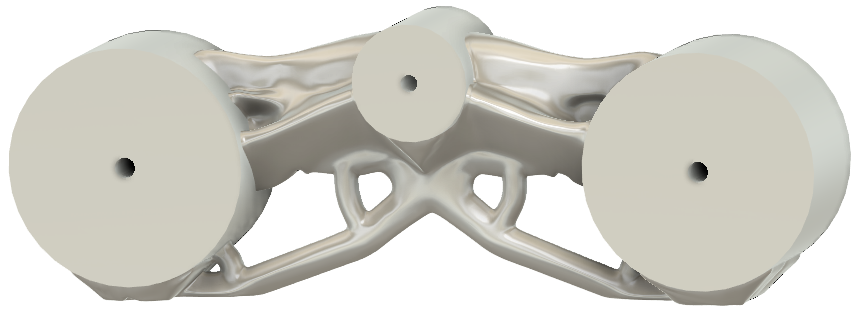
We will be using a Renishaw AM250 to manufacture the design, which requires the Additive Build Fusion extension. First, we need to fill in the large holes with material so we can later machine them to tolerance. We will do this in the Manufacture workspace by creating a Manufacturing Model in which we Press/Pull the holes to be a smaller diameter.
Now we will create a new setup, selecting the Renishaw machine and our modified geometry. After a little work with the Move command, our part is positioned on the build platform.
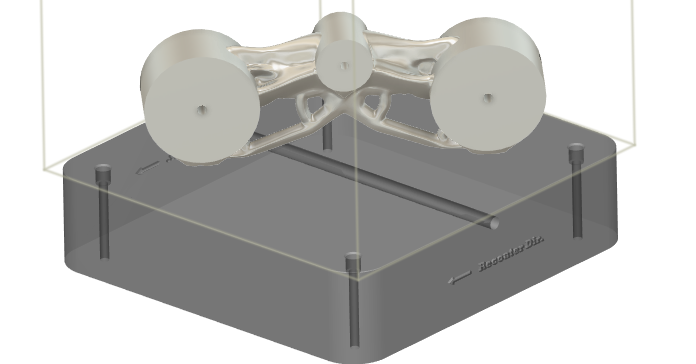
Now we will use the Volume Support command to generate support material.
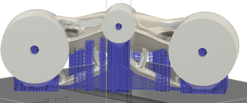
At this point, we are ready to simulate the print, then generate g-code and send it to the machine.
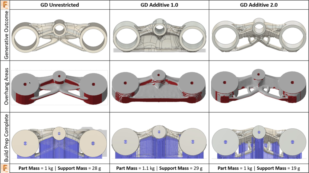
Figure 7 (below) compares the Additive 2.0 design with the unrestricted and existing additive manufacturing solutions, and we see a similar trend as in the previous example. The Additive 1.0 results are heavier, require as much support as the unrestricted part, and suffer surface quality issues. Additive 2.0 improves shape quality, reduces support material required, and brings the part mass back to nearly equal with the unrestricted outcome.
Try Additive 2.0 Out For Yourself
We hope you are just as excited about these additive manufacturing improvements as we were to bring them to the product. While the images in this blog tell a great story, we wanted to provide you the models that we used to demonstrate the improvements, so you have a look for yourselves. These models are ready to run, open them, and generate the available studies.
Additive 2.0 V Shaped Tension Bar Setup
Additive 2.0 Motorcycle Triple Clamp Setup
If you have any questions or comments about our new additive manufacturing constraints, please contact us at generativedesignhelp@autodesk.com. Also, I want to share a big thanks to an awesome team of experts who have been developing and validating this solution and to Ben Weiss, Adam Day, Matt Oosthuizen, and Divy Kishor Tiwary for helping me author this blog post. I wish you all a happy holiday season and a Happy New Year!
