This post is also available in: Deutsch (German)
Learn how to use Thevenin’s Theorem to calculate current and voltage across a load resistor in a linear circuit.
Tired of recalculating your entire circuit every time you change your load resistance? Thevenin’s Theorem can help.
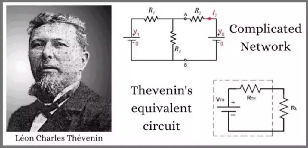
How to calculate load current and voltage with Thevenin’s Theorem
There are a variety of methods available to analyze complex electrical circuits. These include Mesh Analysis, Nodal Analysis, or Kirchhoff’s Circuit Laws. The problem is when you’re designing a DC power network, you’ll have a load whose value will change as your design process unfolds. Rather than having to recalculate the current and voltage of your entire circuit each time your load changes, you can simplify this process with Thevenin’s Theorem. This blog will look at simplifying any complex linear circuit into a single voltage source and series resistance. From there, we can use our Thevenin equivalent circuit to calculate our current and voltage quickly. Let’s get started.
Elevate your design and manufacturing processes with Autodesk Fusion
What is Thevenin’s Theorem?
Like all other mathematical and scientific theories/laws, Thevenin’s Theorem was invented by the man himself, Léon Charles Thévenin. Thévenin was a French telegraph engineer born in Meaux, France. After his time in the corps of telegraph engineers, he was appointed as a teaching inspector at the École supérieure de télégraphie in 1882. It was here that he became interested in the measurement of electrical circuits. At that time, he used the two available methods – Kirchhoff’s Circuit Laws and Ohm’s Law.
In an attempt to make complex circuit analysis easier for every engineer, Thevenin developed his now famous Thevenin Theorem. This theorem reduces complex circuits into simplified Thevenin equivalent circuits.
Thevenin’s Theorem states that you can take any linear circuit, which can contain several emfs and restrictive components, and simplify the circuit into one voltage source adn series resistance connected to a load.
Why use Thevenin’s Theorem?
In this case, a linear circuit is one that includes passive components like resistors, inductors, and capacitors. However, if you’re working with a circuit that includes gas-discharging or semiconductor components, then you have a nonlinear circuit. This is not what Thevenin’s Theorem was suited for. So why use this theorem for linear circuit analysis?
- Efficiency. Thevenin’s Theorem provides an easy method for analyzing power circuits, which typically have a load that changes value during the analysis process. This theorem provides an efficient way to calculate the voltage and current flowing across a load without having to recalculate your entire circuit over again.
- Focus. Thevenin’s Theorem also provides an efficient way to focus your analysis on a specific portion of a circuit. This allows you to calculate the voltage and current at a specific terminal by simplifying the rest of the circuit with Thevenin’s equivalent.
For example, check out the circuit below. Here we have resistor R2 as our load. We want to calculate the voltage and current flowing through this resistor without having to use a time-consuming analysis method like Branch Current, Mesh Current, etc. each time the value of the load resistor changes.
To make this easy, we can use Thevenin’s Theorem to remove the load resistance and voltages. We then simplify the rest of the circuit as a single voltage source and series resistance. In this simplified Thevenin Circuit, the two resistors R1 and R3, along with secondary voltage B2, are all simplified into a single voltage source and series resistance. As far as the load resistor is concerned, the simplified voltage and resistance will operate the same as our original circuit. Now we just have two simple variables to work with in our calculations.
Thevenin’s Theorem in Action
Let’s take a look at an example circuit and calculate the current flowing through a load resistor between two terminals. The process for analyzing a DC circuit using Thevenin’s Theorem requires the following steps:
- Find the Thevenin Resistance by removing all voltage sources and load resistor.
- Find the Thevenin Voltage by plugging in the voltages.
- Use the Thevenin Resistance and Voltage to find the current flowing through the load.
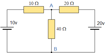
Here is the example circuit we’ll be working with:
Step 1 – Thevenin Resistance
First, we must remove the 40 Ohm load resistor connecting terminals A and B and all voltage sources. Doing this will provide an open circuit at zero volts, leaving just the two resistors wired in series.
To calculate the total Thevenin Resistance, we can use the following process:

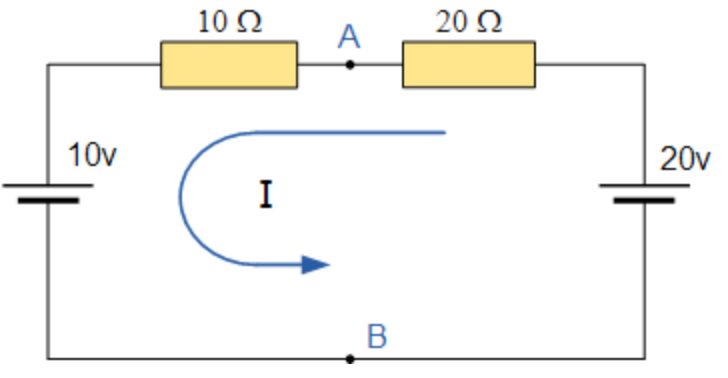
We now need to reconnect the two voltages back into the circuit, and as and calculate the current flowing around the loop:

Step 2 – Thevenin Voltages
This current of 0.33 amperes (330mA) is common to both resistors, so the voltage drop across the 20Ω resistor or the 10Ω resistor can be calculated as:
(VTh=Voc=Vab)
Our current to calculate the voltage drop, which is:
VAB = 20 – (20Ω x 0.33amps) = 13.33 volts
or
VAB = 10 + (10Ω x 0.33amps) = 13.33 volts, the same.
Step 3 – Load Current
Now that we have our Thevenin Resistance and Voltage we can put our Thevenin equivalent circuit together with our original load resistor as shown below.
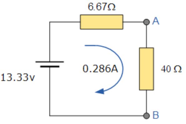
From here, we can use Ohm’s Law to calculate the total current flowing across the load resistor like this:

Ready to put your skills to the test? Use Thevenin’s Theorem to find the RTH resistance and VTH load for the circuit below!
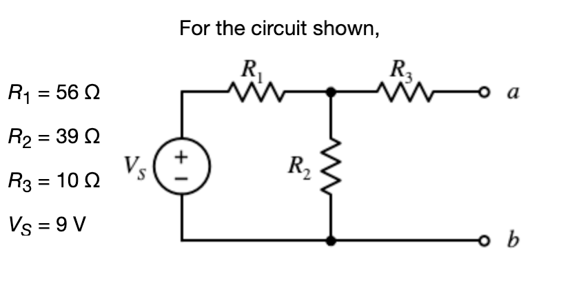
Remember the three-step process:
- Find the Thevenin Resistance by removing all voltage sources and load.
- Find the Thevenin Voltage by reconnecting the voltage sources.
- Use the Thevenin Resistance and Voltage to find the total current flowing through the load.
Keep it simple
Planning to design a DC power circuit? Chances are you’ll be incorporating a load whose value will change during your circuit analysis. Rather than having to recalculate the entire circuit each time you change the value of this load, you now have Thevenin’s Theorem to make your job easy.
This theorem allows you to take any complex linear circuit with a variety of resistive components and EMFs and simplify it into a Thevenin equivalent circuit. With this simplified circuit, you can easily calculate the total current and voltage flowing through a load. This is a huge time saver for any engineer who needs to analyze circuits for power designs and other complex applications efficiently.
For those of you visual/kinesthetic learners, be sure to check out the video below that shows how to use Thevenin’s Theorem step-by-step.
Ready to design your first power circuit? Try Autodesk Fusion 360 electronics for free today!