Want to maintain an automatic connection between your PCB and enclosure when updates occur? Edit in Place ensures your MCAD and ECAD designs always stay in sync.
This recent article explained the basic workflows to create and use 3D PCB in Fusion 360. When working with 3D PCBs, you want your board outline to automatically update after the enclosure is changed. The Derive PCB from Sketch command is one way to make this happen. This method has an issue, though: you cannot insert the 3D PCB back into the enclosure document unless you break the link inside of the 3D PCB document. Once you break the link, it’s impossible to synchronize the source sketch and the outline again.
To solve this problem, you can create a three-document assembly. However, you might not want to have the additional document, or if you have built the enclosure, it’s too late to create the sketch document. In this post, I’ll introduce a different solution for this workflow: Edit in Place.
How to build a PCB outline and keep association with your sketch
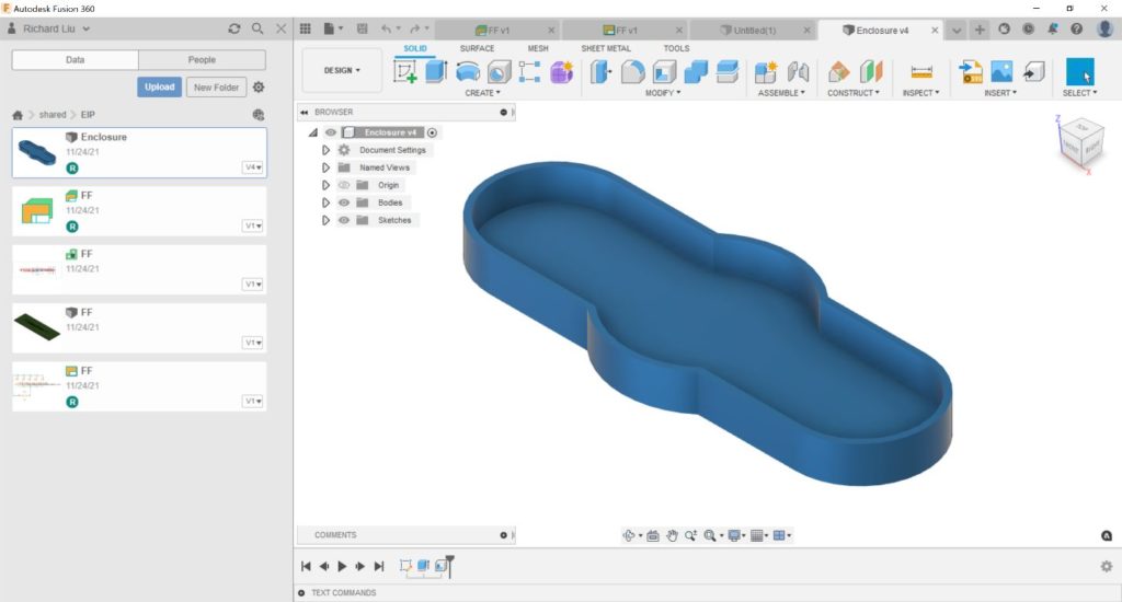
Follow these steps to synchronize between your MCAD and ECAD designs. In this example, we’ll use the finger fidget enclosure design below:
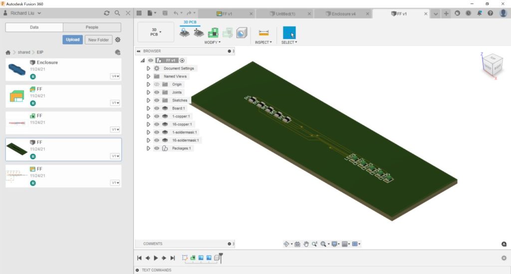
- First, we can just create the 3D PCB using any simple outline. I used a rectangle for this example.
2. Activate the enclosure document.
3. Find the 3D PCB document from the data panel, right-click it, and select Insert into Current Design.
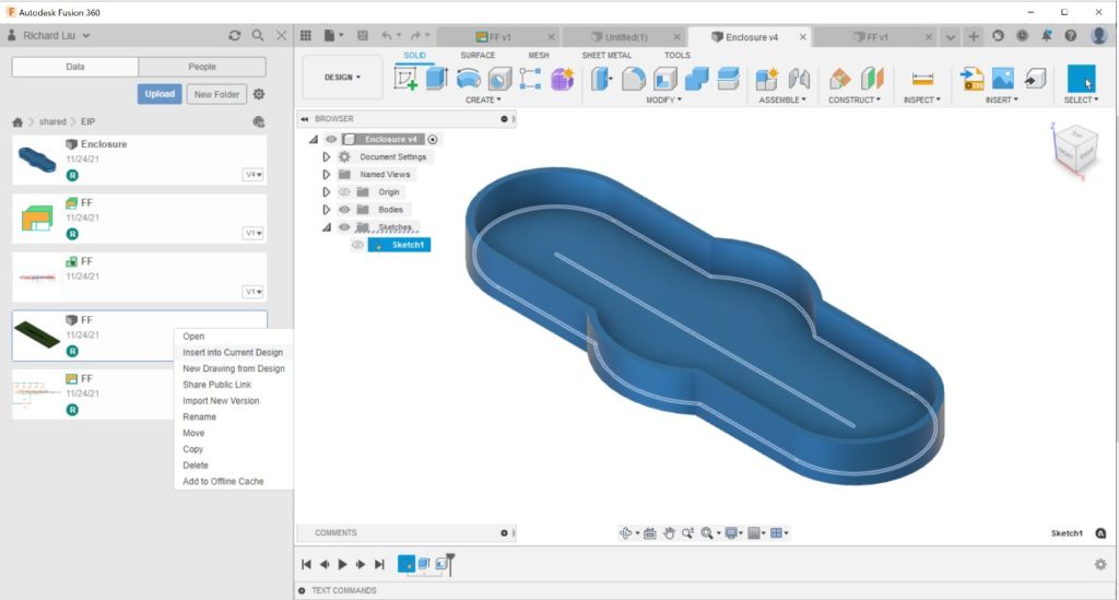
You might need to move the 3D PCB into the proper position relative to the sketch profile.
4. Right-click the newly created component for the board, then select Edit in Place.
Navigating the Edit in Place Environment
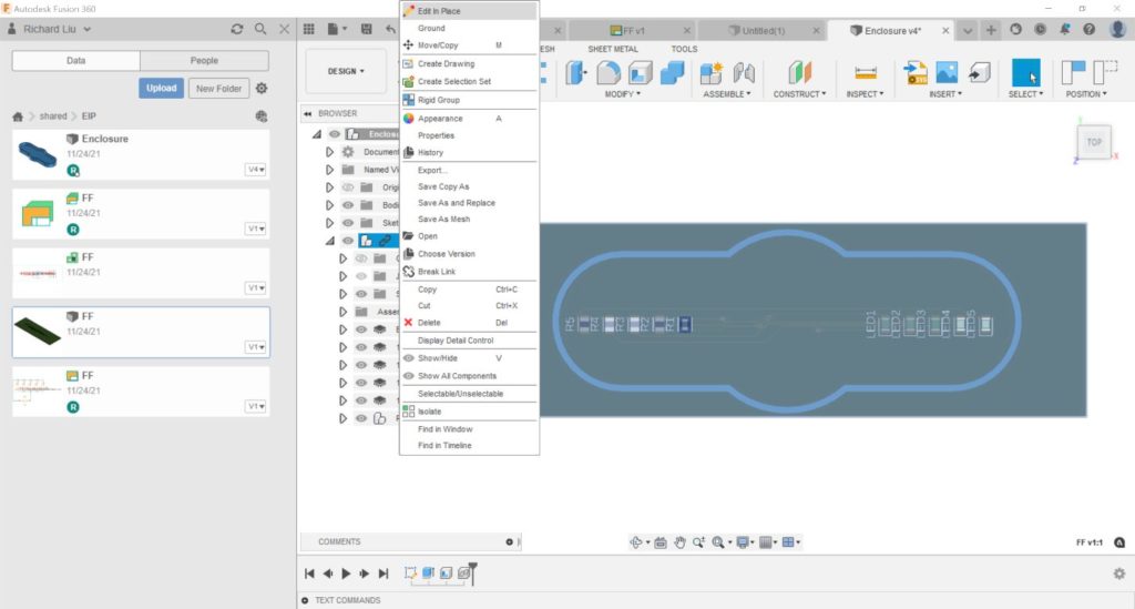
5. We are now in Edit in Place mode. Edit in Place makes it possible to edit an external component in the context of the assembly without leaving the parent design. Find the sketch for the board outline, right-click, and then click Edit Sketch.
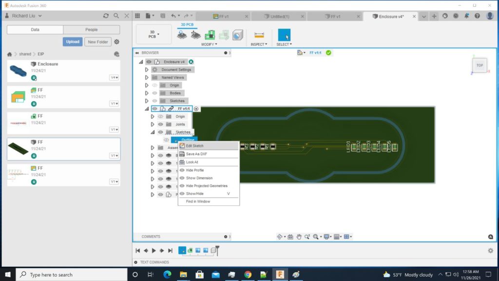
6. This brings us to the sketch environment where we can define our new outline sketch. Since we want to use the sketch geometries from the enclosure document for our board, we simply remove the previous outlines (the rectangle in this case), then use the Project command to project geometries from the enclosure sketch into our board outline sketch:
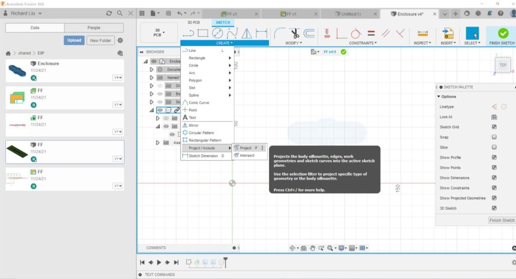
The projected sketch now tracks the change of the source sketch — this step is absolutely key to this method.
7. Now you’re ready to finish the sketch. You might find that the board shape does not change yet and that a warning appears:
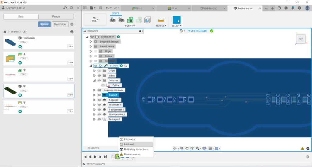
This warning happens because we deleted the old outline geometries. We need to let the 3D PCB know which sketch profile we will use to build the outline. Right-click on the board node in the timeline and select Edit Board.
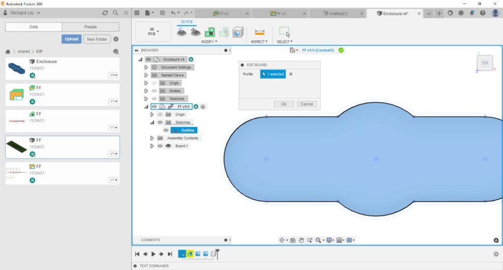
In the Edit Board command, select the projected sketch profile. Now we can achieve the correct board shape:
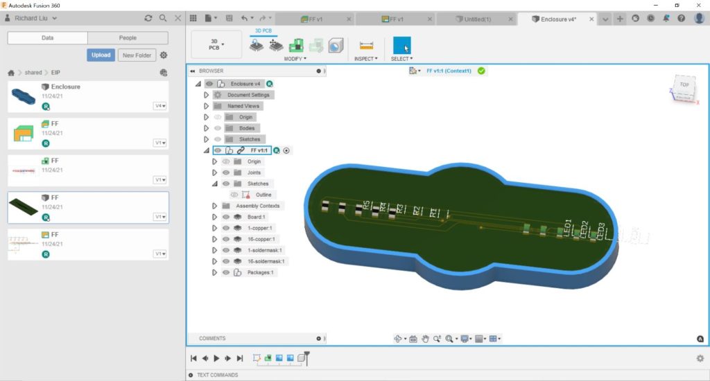
8. Click the green checkmark on the top to exit the Edit in Place environment. To verify the 3D PCB can track the changes of the enclosure, you can edit the sketch. For example, here I made the middle circle smaller. You will see there is a small warning mark beside the Assembly Contexts node.
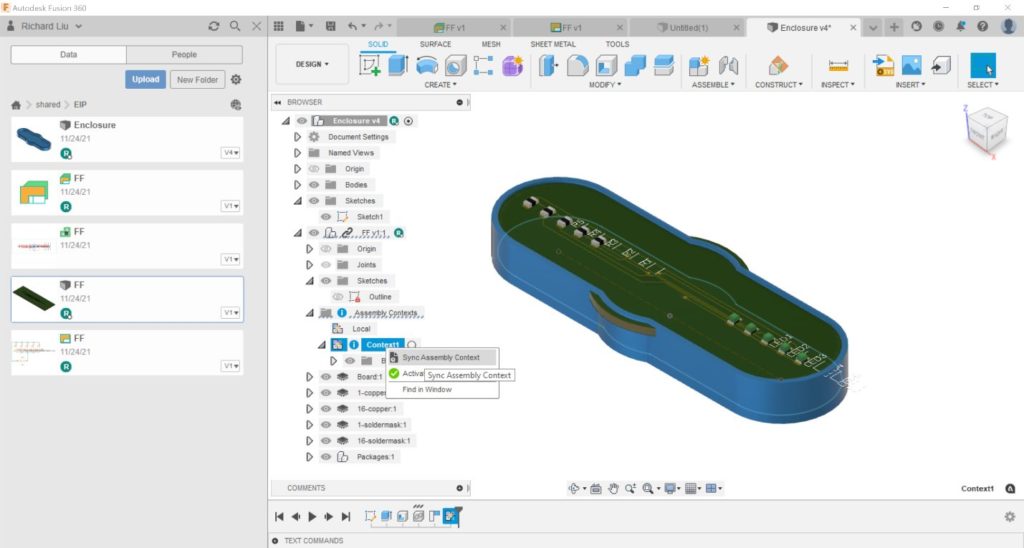
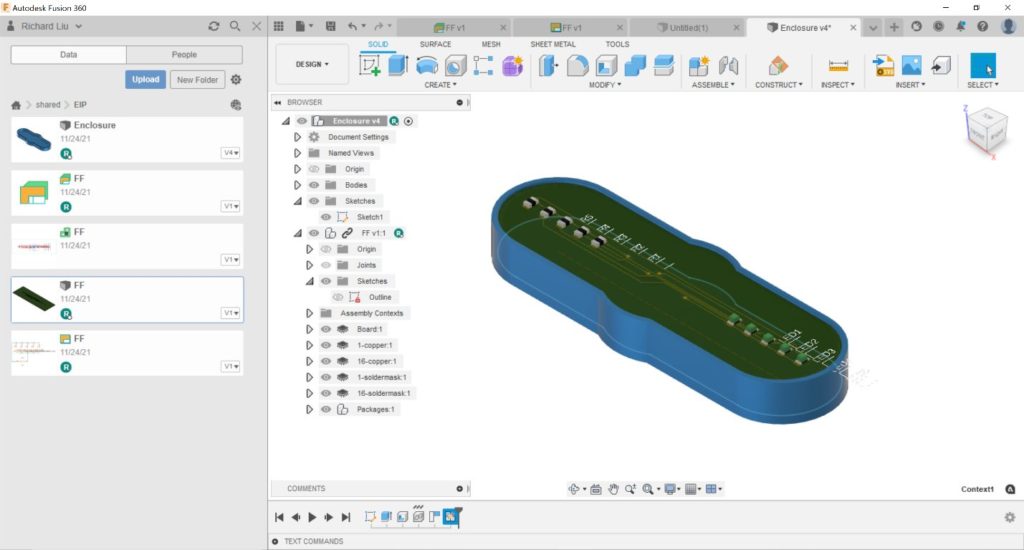
Now if you click Sync Assembly Context, the board shape will be updated.
That’s all. As usual, if you have additional questions about Fusion 360 electronics workflows, please post your questions on the Fusion 360 Electronics Forum. Not using Fusion 360 electronics yet? Here are five reasons to start.

