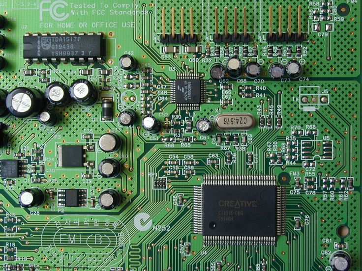
Learn about what decoupling capacitors (bypass capacitors) are and how they help to smooth out the voltage in a power supply.
It’s pretty standard for beginner electronic designers to forget just how unstable input voltages can be, despite how sturdy that power supply might look. And when you’re working with microcontrollers or microprocessors in your digital circuit, the slightest fluctuation in your voltage can lead to undesired results. So what can you do to keep your ICs running with smooth, clean voltage? Use decoupling capacitors! Here’s more information about what they are and how to use them.
What are decoupling capacitors?
A decoupling capacitor (also referred to as a bypass capacitor) acts as a kind of energy reservoir. You’ll find these guys commonly placed as close as possible to an integrated circuit (IC) on a PCB layout. Once fully charged, their job is to simply oppose any unexpected change in your input voltages from a power supply. When a decoupling capacitor is in place, it will do one of two things:
- If the input voltage drops, then a decoupling capacitor will be able to provide enough power to an IC to keep the voltage stable.
- If the voltage increases, then a decoupling capacitor will be able to absorb the excess energy trying to flow through to the IC, which again keeps the voltage stable.
All of this is needed because there’s a ton of electrical noise on a typical circuit board and the steady 5V that we think we have flowing all over the place is actually jumping around as it moves from component to component.
Some components like integrated circuits rely on their input voltage being as steady as possible, so when you place a decoupling capacitor next to an IC, you’ll be able to protect those sensitive chips by filtering out any excess noise and creating a nice, steady source of power. What happens if you don’t use decoupling capacitors next to your IC? Well, you’ll likely wind up with a processor that starts skipping instructions and behaving abnormally.

How to use decoupling capacitors
Check out the schematic below; it shows off a typical application of how you might use decoupling capacitors when placed next to an IC. As you can see, you’ve got a 10uF capacitor sitting the furthest away from the IC, which helps to smooth out any low-frequency changes in an input voltage.

And then you have the 0.1uF capacitor placed closest to the IC. This one will help to smooth out any of the high-frequency noise in your circuit. When you combine these two capacitors, you’ll be delivering a smooth, uninterrupted voltage to your IC to work with. When working with decoupling capacitors in your own design, keep these three things in mind:
- Placement. You’ll always want to connect your decoupling capacitors between your power source, whether that’s 5V or 3.3V, and ground.
- Distance. You’ll always want to place your decoupling capacitors as close as possible to your IC. The farther away they are, the less effective they’ll be.
- Ratings. As a general guideline, we always recommend adding a single 100nF ceramic capacitor and a larger 0.1-10uF electrolytic capacitor for each integrated circuit on your board.
Saving your integrated circuit’s life
There you go, everything you might need to know about what decoupling capacitors are in only 5 minutes in today’s Electronic Byte. Integrated circuits are a sensitive bunch, and without a smooth power source, you’ll likely be troubleshooting skipped instructions and other strange behaviors. By throwing a set of decoupling capacitors next to one of your ICs, you’ll ensure that they’re always getting a smooth input voltage, regardless of what kind of electrical noise is on your PCB.
Ready to start your next electronics design project with decoupling capacitors? Try Autodesk Fusion today!