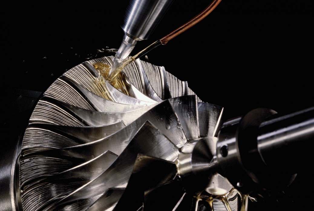
CNC machining is a subtractive manufacturing technique that shaves away a solid block of material to create high-precision parts. Multiple tools are used during this process by cutting in at least three axes, or directions. As its name suggests, the 5-axis version of CNC machining can move tools and parts in five different directions or axes at once. They are the X, Y, and Z axes along with the A and B axes.

The history of 5-axis machining
5-axis machining evolved from its 3-axis counterpart, which was widely used in the manufacturing industry for many decades. It only used three axes, which were the X, Y, and Z axes that correspond to the three basic dimensions of any 3D space or object.
The concept of a 5-axis process was first discussed by Golden E. Herrin in an article in 1995. In his article, Herrin traces the process back to numerical control which he first encountered in 1958. This pioneering machine was an electric tracing of a vertical mill which was built by Cincinnati Milacron and commissioned by the United States Air Force.
Elevate your design and manufacturing processes with Autodesk Fusion
At the time, the concept was considered by many to be impossible to achieve. However, due to the advancements in computer systems and design software, CNC designers were able to turn the concept into reality. Now CAM software like Autodesk Fusion has also made it easy to create codes for the machine to move in a uniform fashion. Its functions, such as tool path optimization, allow for the easy editing of tool paths without lengthy recalculations so you can save time and get the most out of a machine.
All about the axes
The five axes in CNC machining are paths that the parts or tools can move along simultaneously. The main axes: X, Y, and Z, are part of the basic Cartesian Coordinate System first proposed by the mathematician and philosopher, Rene Descartes in the 1500s. It’s used to describe three-dimensional space and can be visually represented as three perpendicular lines going in different directions. The three lines, or axes, intersect at a point in the center called the origin which is used as a reference point to measure the length along each axis.
The last two axes – A and B – are more difficult to visualize. These two axes rotate around the main X and Y axes and can be visualized as the orientation of the object moving down the main axes. An additional axis called C which rotates around the Z-axis also exists but is not usually used in CNC machining processes.
Different configuration types are also available for these systems and are determined by which two of the three rotation axes are used. For example, trunnion-style machines are operated on an A-axis and a C-axis. This allows for rotation about the X-axis and the Z-axis only. In contrast, swivel-rotate-style machines operate with a B-axis and a C-axis, allowing rotation about the Y-axis and the Z-axis, respectively.
Benefits of 5-axis systems
These systems are considered superior to traditional 3-axis systems and their popularity continues to grow each year. The addition of the A and B axes opened the door to an infinite number of manufacturing possibilities. Cutting tools can now approach the manufactured product from all possible directions. This enables easy undercutting without requiring the repositioning of the entire system, a feat that is not possible on machines with less than five axes unless the product is repositioned.
Additionally, less material handling takes place with the product due to the reduction in the amount of repositioning required. This leads to time savings and reductions in human errors as well as production costs. Complex parts can now be created using the additional axes, and jobs that only require three axes can be completed faster using a 5-axis machine. This is because the cutting tool stays tangential to the cutting surface, which in turn removes more material on each pass.
Another benefit of this process is an improved surface finish. This is because having different orientations of the parts allows for the product to get closer to the cutting tool. This leads to less vibration of the tool and an overall smooth surface finish. Software such as Autodesk Fusion can help complete this process by offering a vast library of tool paths for greater optimization and minimal manual polishing.