In this tutorial, we explore the process of working with imported mesh files in Fusion, creating our own new geometry, and incorporating them into the mesh body for 3D printing. This can be useful when you find a file online that’s already converted to an STL, OBJ, or 3MF format, and you need to add something or modify it in some way.
Autodesk Fusion isn’t primarily a mesh modeling program, but it has plenty of tools to handle this type of work. The best initial approach is to generate face groups and try to convert the mesh. However, for a design with over 10,000 faces, like the end of a GoPro mount we are working with, this process may not be feasible.
Here is a step-by-step guide on how to modify imported mesh models.
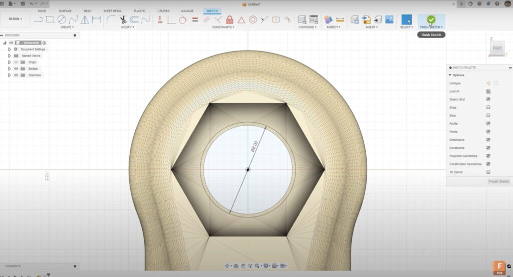
1. Increasing the Diameter of the Hole:
First, we go to our solid tools and create a sketch on the right plane. We add a circle with a 6 mm diameter, slightly larger than the existing hole. If the screw didn’t fit your previous 3D print, increasing the diameter is a common solution. We then extrude this sketch symmetrically in both directions.
2. Adjusting the Model for Mesh Combine:
To use the Mesh Combine tool, we need to convert our B-rep or solid body to a mesh body through a process called tessellation. We can then use the Cut tool in Mesh Combine to select our target and tool. Fusion will use the tool body (the extruded cylinder in this case) to remove the overlapping sections of the underlying mesh. It’s crucial to match the number of mesh elements between the two bodies for the best results.
3. Creating a New B-rep on the Bottom:
Next, we create a new, more complex B-rep on the bottom using a two-point rectangle. We add dimensions and extrude it to form the desired shape. It’s essential that this new body is at least touching or overlapping with the existing mesh for the combined process to work correctly. Once created, we add rounded fillets to the corners and a chamfer to the top edge for better 3D printing results.
4. Creating New Mounting Options:
At the bottom, we create some new mounting options by placing a couple of circles, ensuring the insides and outsides are the same. We add dimensions and extrude these as well, just like any other solid modeling process.
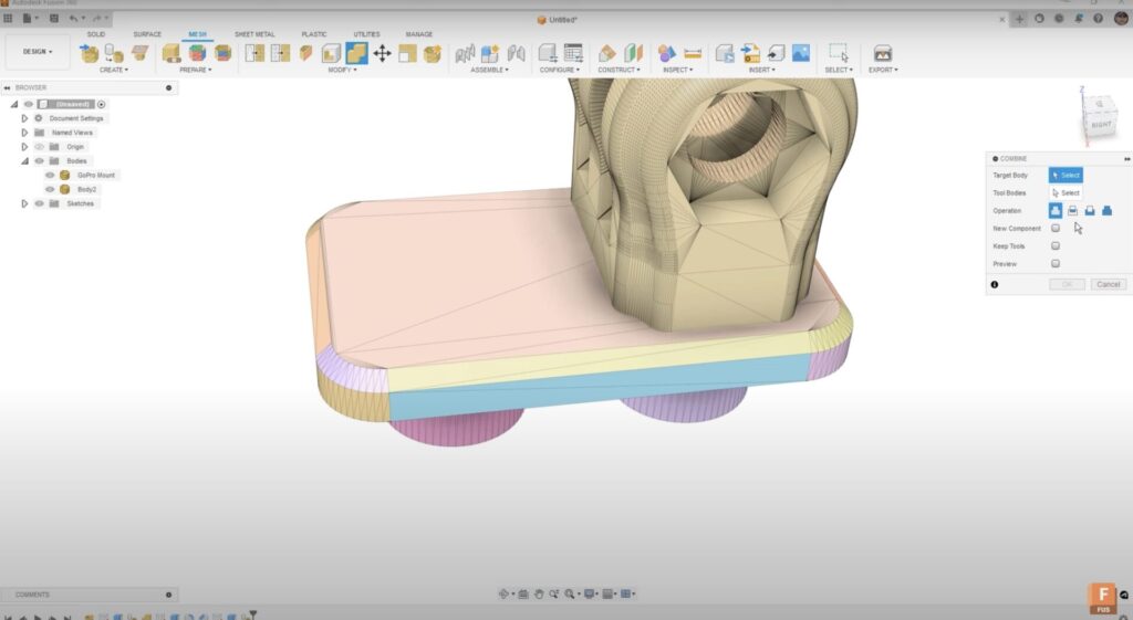
5. Combining the Bodies:
Now we have a solid body (B-rep body) and a mesh body that we want to combine. We tessellate the new solid body and combine it with the mesh body using the Join option. This process removes the overlapping sections and remeshes the intersections. Depending on the complexity of the imported model and the number of triangles, this process may take some time.
6. Inspecting the Final Model:
Using the Inspect tool, we can take a look at a section analysis, which shows a clean intersection between the two mesh bodies, with any overlap completely removed. This model is now ready for 3D printing.
The beauty of Fusion is that all processes are captured in the timeline, allowing us to go back and modify features as needed. Alternatively, we can work directly with the mesh in Direct Edit mode if preferred.
This tutorial illustrates how Fusion can be a powerful tool for modifying and enhancing imported mesh models for 3D printing. With practice, you can make slight adjustments to these models, adding or modifying features as needed.
Full-access Fusion Trial
Unlock all of Fusion's advanced features and functionality - free for 30 days.