Geometric dimensioning and tolerancing (GD&T)

Geometric dimensioning and tolerancing (GD&T) in design and manufacturing

Communicate design intent with precision and confidence. Ensure proper fit, form, and function with industry-standard GD&T annotations.

Geometric dimensioning and tolerancing

What is geometric dimensioning and tolerancing (GD&T)?

Geometric dimensioning and tolerancing (GD&T, or GDT) annotates part designs with descriptions of the part’s shape, size, and allowable manufacturing variations.

Traditionally communicated through 2D technical drawings, modern GD&T software now embeds this information directly into the 3D CAD model, streamlining the design process.

History of GD&T

History of GD&T

In 1940, naval engineer Stanley Parker developed a more reliable and cost-effective system than specifying part features by using coordinate measurements and plus/minus tolerances. 

This proto-GD&T system led to the enactment of a military standard. Today, manufacturers worldwide follow the trade GD&T standards, which were most recently updated in the late 2010s.

GD&T in manufacturing

GD&T in manufacturing

Standardized GD&T systems from the American Society of Mechanical Engineers (ASME) and the International Organization for Standardization (ISO) have been game-changers in modern manufacturing. 

The software encourages you as a designer, manufacturer, or inspector to clearly communicate the functional reasons behind a product’s dimensions. 

When applied properly, GD&T can cut down on errors and rework, speed up time to market, and minimize production costs. Reduced inspections and reject rates help boost efficiency and elevate the quality of your work. 

Use GD&T to improve manufacturing processes, unleash creativity, and achieve remarkable results.

Why is GD&T useful?

Why is GD&T useful?

GD&T standards revolutionized how we approach design compared to older methods, which relied on linear dimensions and lengthy notes. 

By clearly defining both design intent and inspection requirements, GD&T offers unmatched precision and efficiency. When you and your team understand how to use and interpret GD&T, it becomes a powerful tool for transparent communication across all disciplines.

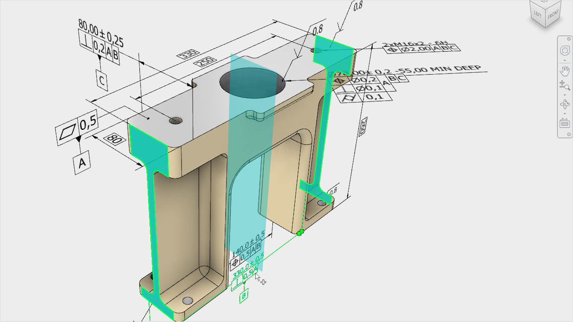
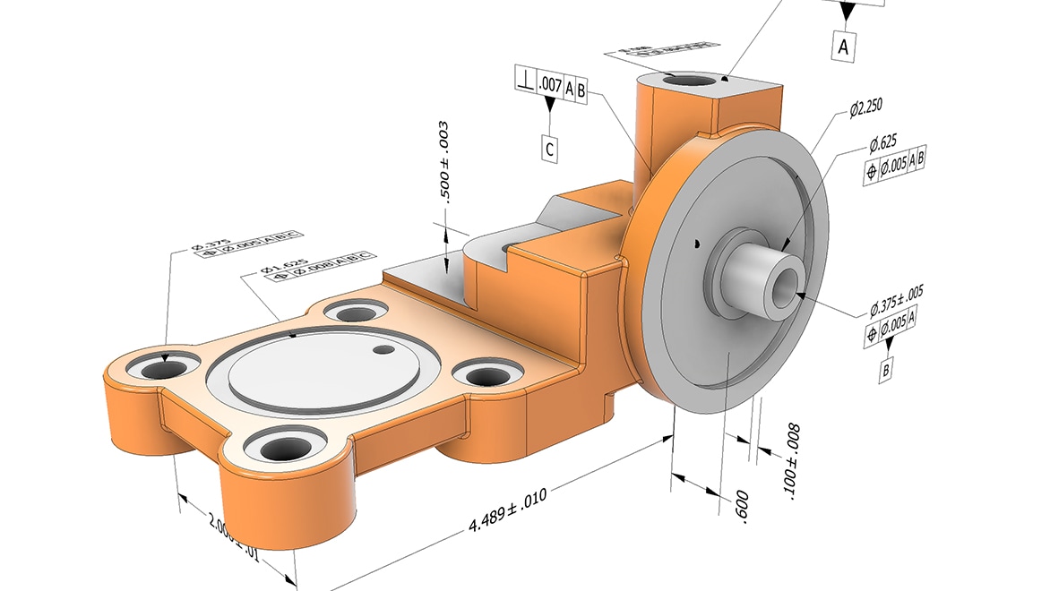
Current GD&T often embeds directly into 3D models through software so you can easily relay design details. Standard-conforming GD&T must include “semantic” tolerances, meaning it follows the logic of the ASME and ISO standards. While GD&T software might not enforce all these rules, it’s up to you to annotate your designs accurately to achieve the best results. 

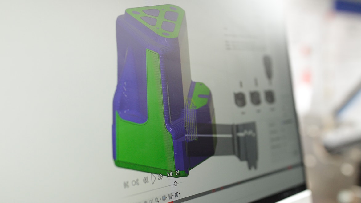
Even with the complex geometries of generatively designed parts, GD&T remains valuable. You can use it to create features that connect to other parts and define them with standard geometric shapes and datums. 

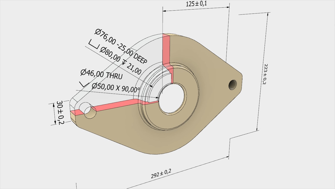
CAD models are theoretically perfect, but real-world parts can never be flawless. GD&T sets acceptable tolerance ranges to ensure parts fit and function properly without the extra costs of tighter tolerances. Well-enacted GD&T can improve quality, cut costs, and accelerate time to market, synchronizing the efforts of designers, machinists, and QA with clear, symbolic language.

Autodesk Inventor with GD&T

Achieve unmatched precision with Autodesk GD&T tools

Unlock new levels of design precision with Autodesk’s GD&T tools. Easily integrate detailed GD&T annotations into your 3D models to improve their accuracy and efficiency, from design to production. Transform your workflow with Autodesk’s GD&T software, and bring clarity and consistency to every project.

Autodesk design software for GD&T

Professional-grade product design and engineering tools for 3D mechanical design, simulation, visualization, and documentation.


Cloud-based 3D CAD/CAM/CAE software for product design


Inventor Tolerance Analysis software is designed to understand the cost impact of dimensional variation. 


2D and 3D CAD tools, with enhanced insights, AI-automations, and collaboration features. Subscription includes AutoCAD on desktop, web, mobile, and seven specialized toolsets.


Get Inventor + AutoCAD + Autodesk Fusion + more—Professional-grade tools for product development and manufacturing planning.


Inspect complex, free-form surfaces across a range of hardware devices—available as Standard, Premium, Ultimate


Benefits of using GD&T

Carrying out GD&T well leads to several valuable benefits, including cost-effective and timely production of reliable parts with less error and scrap.

Standardized design language

GD&T describes a part’s tolerances better than linear dimensions, helping manufacturers meet your design intent without creating multiple costly prototypes.

Process control

With strong GD&T practices, your teams can work in parallel with smoother operation—for example, more successful assembly and speedier quality control.

Leads to reliable assembly

GD&T enables you to produce qualified parts with fewer rejects, and those parts are assured to fit perfectly in assemblies every time.

Crystal-clear communication

GD&T is a symbolic system, so can be universally understood no matter what languages you know. That makes GD&T extremely effective for international projects.

Tolerances are good for business

Overly tight tolerances increase cost and production time due to new tooling investments and unnecessarily high reject rates. GD&T helps you find the right balance—maintaining functionality at a lower price.

Easily repeatable processes

When you’re confident in proper GD&T documentation, production and inspection processes are repeatable and scaleable. Inspection is digitized and automated, with the data captured for your audit trail.

GD&T Concepts

Datum

Datum

A datum is a precise reference point, line, or plane on a part that serves as the foundational starting point for all dimensional measurements. In GD&T, datums are essential for establishing a reliable coordinate system, ensuring accuracy throughout the manufacturing and inspection. They anchor the part’s design, enabling other features to be confidently measured and aligned. 

Feature

Feature

A feature is any distinct physical element of a part—such as a surface, hole, slot, or edge—subject to measurement. Features are the building blocks of design in GD&T, categorized by their regularity of complexity. Annotations and symbols are applied to these features to define their dimensions and permissible variations. They ensure each element meets its functional requirements.

Tolerance

Tolerance

Tolerance in GD&T sets the boundaries for how much a part’s feature can deviate from its ideal size, shape, orientation, or location while still performing its intended function. By defining acceptable variation ranges, tolerances ensure parts fit together seamlessly and operate as designed. GD&T uses various tolerances to communicate these limits with clarity and precision.

Common GD&T Symbols
Image courtesy of Conturo Prototyping

Common GD&T Symbols

GD&T symbols indicate how much a feature can deviate from its ideal shape, position, or orientation, ensuring that parts fit and function correctly. Each symbol represents a specific control, like flatness, perpendicularity, or position. These are split into five categories, providing standardized instructions that facilitate communication for high-quality results.

Industries using GD&T

See examples of industries utilizing geometric dimensions and tolerancing for manufacturing.

A futuristic car is on display on a dock.

Automotive

GD&T is critical for large automotive OEMs using thousands of suppliers and producing millions of complex parts to meet standards and pass inspection.


GD&T for consumer product design

Consumer product design

GD&T ensures a smoother process when prototyping a series of design iterations where products balance functionality, aesthetics, and ergonomics.


An illustration of complex electronics.

Electronics

Mechanical, electronic, and PCB design comprise complex electronics, and GD&T puts suppliers and engineers on the same page.


A close look at industrial machinery.

Industrial machinery

Larger machinery requires many low-volume parts that operate under extreme conditions, making GD&T’s connection between design and manufacturing vital.


A wheeled robot inside a factory.

Robotics

With many intricate parts contributing to highly repetitive, precise movements, robotics need accurate GD&T for calibration, validation, and inspection.


A man examines a design on a laptop while woodworking.

Woodworking and furniture design

Whether dealing with mass-produced furniture or custom-designed boutique pieces, proper GD&T for woodworking helps reduce scraps and rework.


Free geometric dimensioning and tolerancing resources

Learn why it’s important that everyone has the same understanding of what finished parts should look like—and how to use GD&T to get on the same page.


See how adding GD&T to your hole patterns will lead to fewer parts failing inspection.


See how CAD data is consumed by production engineering and CAM systems and why center-tolerance models are a best practice for providing CAD data for manufacturing.

Discover how to add Geometric Dimensioning & Tolerancing (GD&T) and other manufacturing information to your 3D model.

Learn to move seamlessly between 2D sketching to 3D modeling using key Autodesk Fusion workspaces.

Frequently asked questions (FAQ) on GD&T

What is tolerance?

Tolerance in GD&T is the “permitted variation of the specified value of a quantity, expressed as the difference between the permitted maximum and the permitted minimum value,” according to the ISO. The five categories of GD&T symbols (form, profile, orientation, location, and runout) describe the different categories of tolerances. While there is a large variety of GD&T tolerances, they relate to the part’s form, function, and fit.

What is a datum?

The ISO defines a datum as a “designation whose concept is a value.” For example, datums are points, lines, planes, or a combination within the three-dimensional datum reference frame (DRF) of GD&T documentation. Datums on a chart are theoretically perfect, whereas datum features are a manufactured part’s physical slots, holes, faces, and other features whose measurements may vary from the theoretical numbers from the GD&T’s allowed tolerances.

What is the history of GD&T?

Before GD&T, engineers specified production part features using tools like coordinate measurements, plus/minus tolerancing, and X/Y areas. Then, in 1940, a naval engineer named Stanley Parker published the earliest work on geometric dimensioning and tolerance. He developed a proto-GD&T using the idea of “true position” to reduce errors and be more reliable and cost-effective for the many contractors building components during World War II.


The MIL-STD-8 publication became the military standard for GD&T, but it was later canceled. Still, GD&T was here to stay. The current US GD&T standard is the American Society of Mechanical Engineers’ ASME Y14.5-2018; elsewhere in the world, it is the ISO 1101:2017.

What is GD&T used for?

GD&T describes the design intent—rather than simply the geometry—of a part, from the product designers and developers to the assembly and inspection workers. It conveys a part’s manufacturability and functionality better than just linear dimensions.


With proper GD&T, each party touching a product design shares an explicit symbolic language that defines a part’s tolerances and can reduce part scraps, rework, and other errors while finding the most cost-effective tooling and fabrication path for each piece.

Why is GDT important?

  • GDT is important because it communicates a part’s proper look and function, from the designer/engineer to the machinist and finally to the quality engineer. Older dimensioning and tolerancing methods are limited in ensuring that parts fit precisely into an assembly.
  • GDT communicates more information about a part and makes QA and inspection easier because its instructions for geometry and allowable variation are uniform and explicit. GD&T also describes how to place a part for measurement. 
  • GD&T software helps designers to input and benefit from geometric dimensioning and tolerancing information according to industry standards.

What are the five categories of GD&T symbols?

The five categories of GD&T symbols are tolerance controls for form, profile, orientation, location, and runout:

  1. Form controls describe feature shapes like circularity, cylindricity, straightness, and flatness.
  2. Profile controls define a surface’s 3D tolerance zone.
  3. Orientation controls deal with angular dimensions: perpendicularity, parallelism, and angularity.
  4. Location controls like position, concentricity, and symmetry use linear dimensions to indicate feature locations.
  5. Runout controls, including circular runout and total runout, deal with the coaxiality of a surface—how much a feature axis can differ from a datum axis. 

What are some specific benefits of 3D annotation for GD&T?

GD&T in the form of 3D annotation (in Autodesk Inventor, for example) allows the CNC programmer to reference the GD&T while programming the part and helps them to program tolerance inspections into their CNC code. For example, the cutting tool may wear during machining, reducing cut accuracy. In-program inspection will notice that and stop the program so the cutting tool can be replaced and the program restarted.  


Metrology hardware—used to inspect parts manually after machining—can also automatically pick up the tolerances from GD&T in Autodesk Fusion —saving the repeat data input. Autodesk Fusion can then combine the results from the inspection into a report, which can be saved into a PDM or PLM system for future reference.

What is the difference between general tolerance and GD&T?

General tolerance allows for broad, standard dimensions allowances and is usually applied to non-critical features. GD&T offers precise control over a part’s geometry, making sure it functions and fits properly, particularly in complex assemblies.

See more FAQ