Create a flat pattern for an imported sheet metal part in Autodesk Fusion

Autodesk Support

May 16, 2024


Products and versions covered


Issue:

User's have asked how to create a flat pattern for a sheet metal part with a non-F3D format (for example: XT, SAT, STEP) that has been imported into Autodesk Fusion.

Causes:

Non-native parts are imported into Fusion as solids or surfaces and need to be converted into sheet metal components before flattening.

Solution:

Follow the steps to be able to create a flat pattern for the imported part:

Watch this process here: Create a flat pattern for an imported sheet metal part in Autodesk Fusion (screenpal.com)

  1. Open the file in Fusion.
  2. Switch to the sheet metal workspace.
  3. Turn on Capture Design History.
  4. Right-click the top component of the browser tree.
  5. Select Capture Design History at the bottom of the right-click menu.
  6. The timeline should now be at the bottom of the screen. 
  7. Switch into the desired Component in the Browser Tree on the left (click the radial button on the right of the name).
  8. Select Convert to Sheet Metal from the toolbar. 
  9. Select the desired component or body as Source.
  10. Uncheck Show Matching Rules.
  11. Select the desired Sheet Metal Rule.
  12. Click OK.
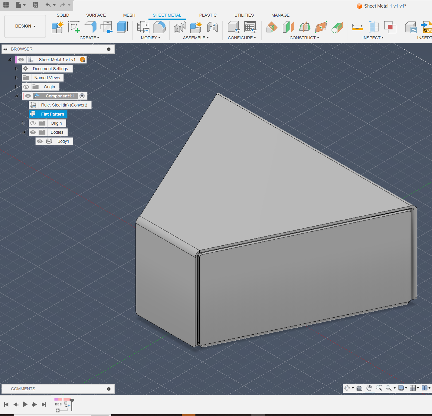
  13. Click Create Flat Pattern.
  14. Choose the desired Stationary Face of the part.
image.png


Products:

Fusion;


Was this information helpful?


Need help? Ask the Autodesk Assistant!

The Assistant can help you find answers or contact an agent.


What level of support do you have?

Different subscription plans provide distinct categories of support. Find out the level of support for your plan.

View levels of support