How to make additional 4th connection to duct tee fitting in Revit

Autodesk Support

Oct 8, 2023


Products and versions covered


Issue:

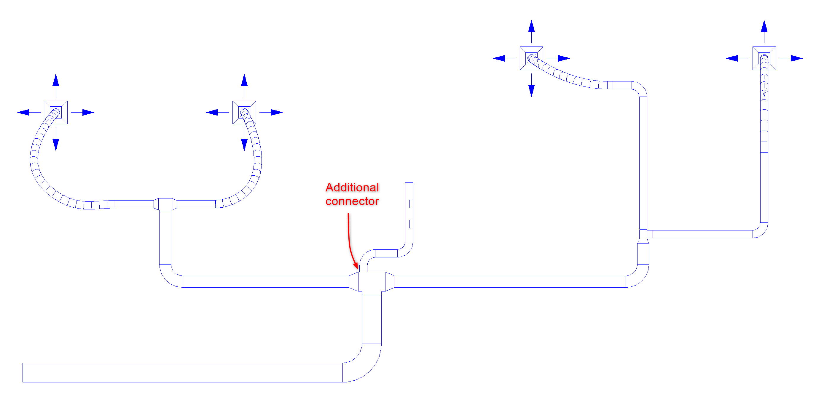
There is necessary to add additional 4th rectangular connector to duct tee to generate Duct Pressure Loss Report and have correct air flow values in duct system in Revit.
image.png

Solution:

To create additional duct connector:
  1. Select duct tee family.
  2. Go to Modify tab > Edit Family.
  3. Revit will open the Family Editor.
  4. Populate duct tee family by save the family with a new name and load into the Revit model go to File > Save as > Family.
  5. File name > Add a new name for the family > Save.
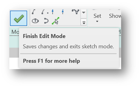
  6. Go to Create tab > Extrusion > Draw Circle (radius 10mm) form on selected Work Plane (choose the surface where connector will be placed) > Modify tab > Choose Finnish Edit Mode
image.png
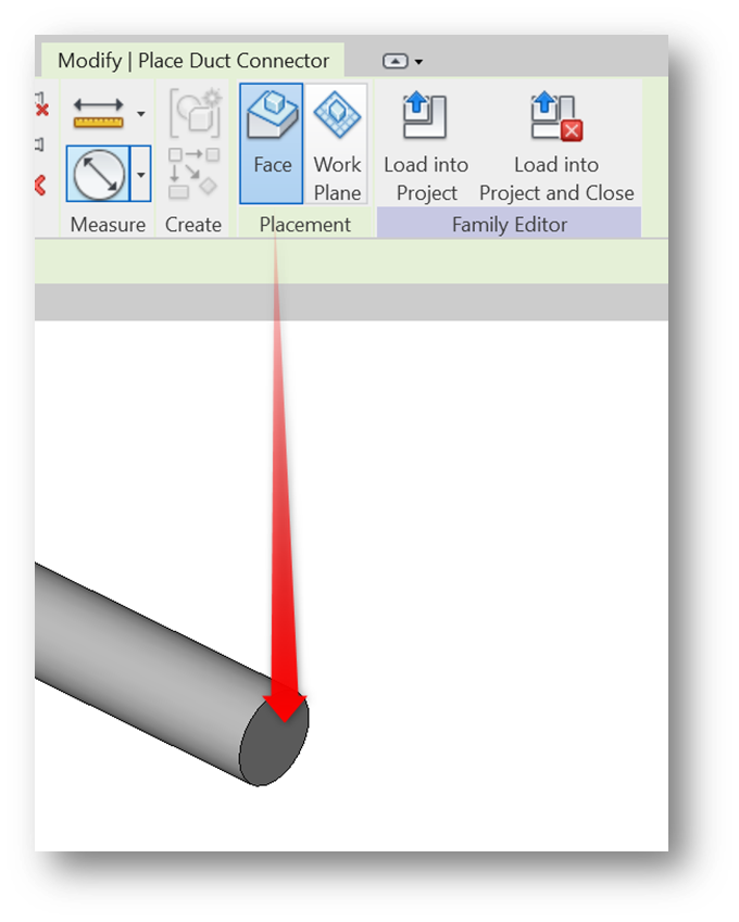
  1. Go to Create tab > Duct Connector > Specify Place Duct Connector on Face of already made Extrusion.
image.png
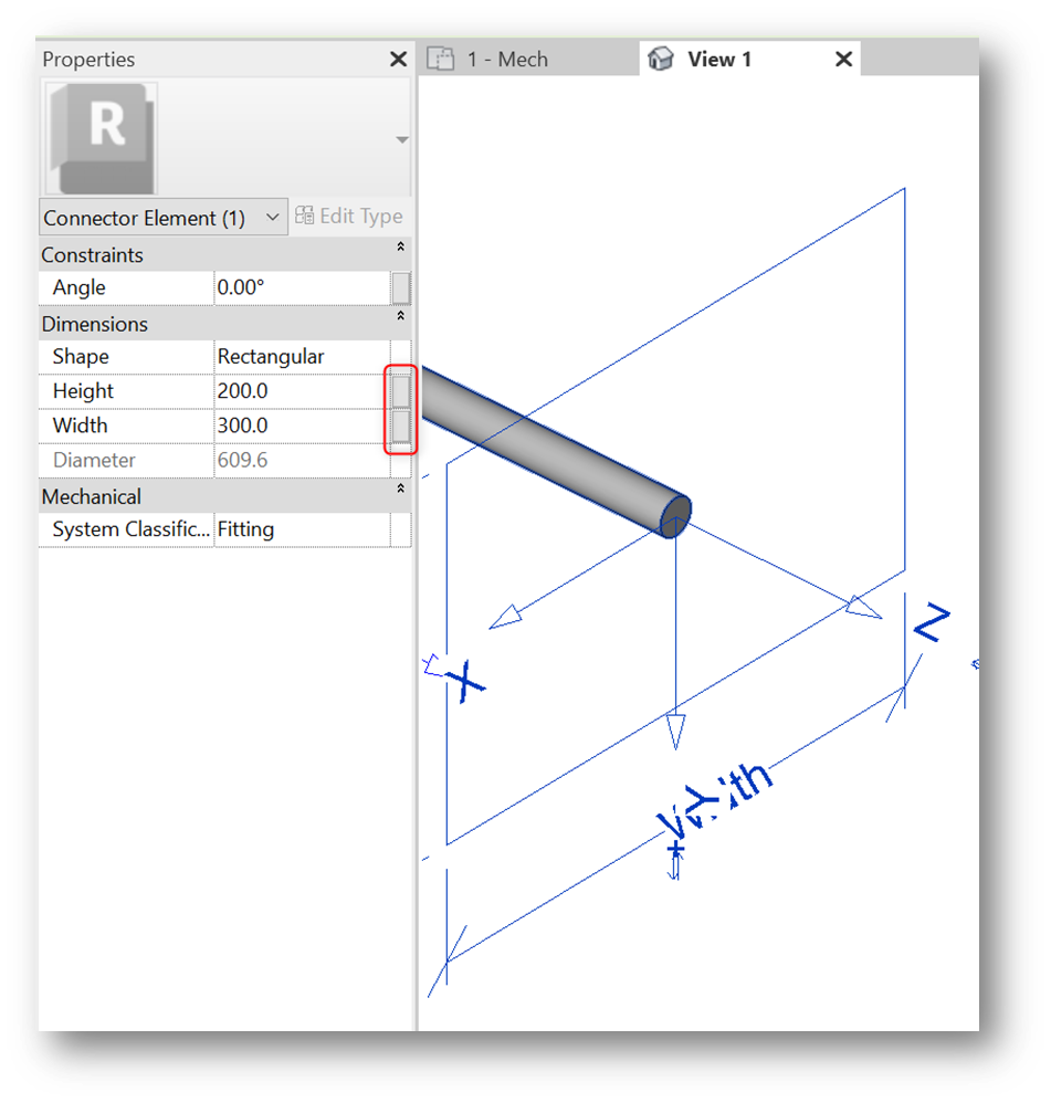
  1. Select connector and add parameters for height and width.
image.png
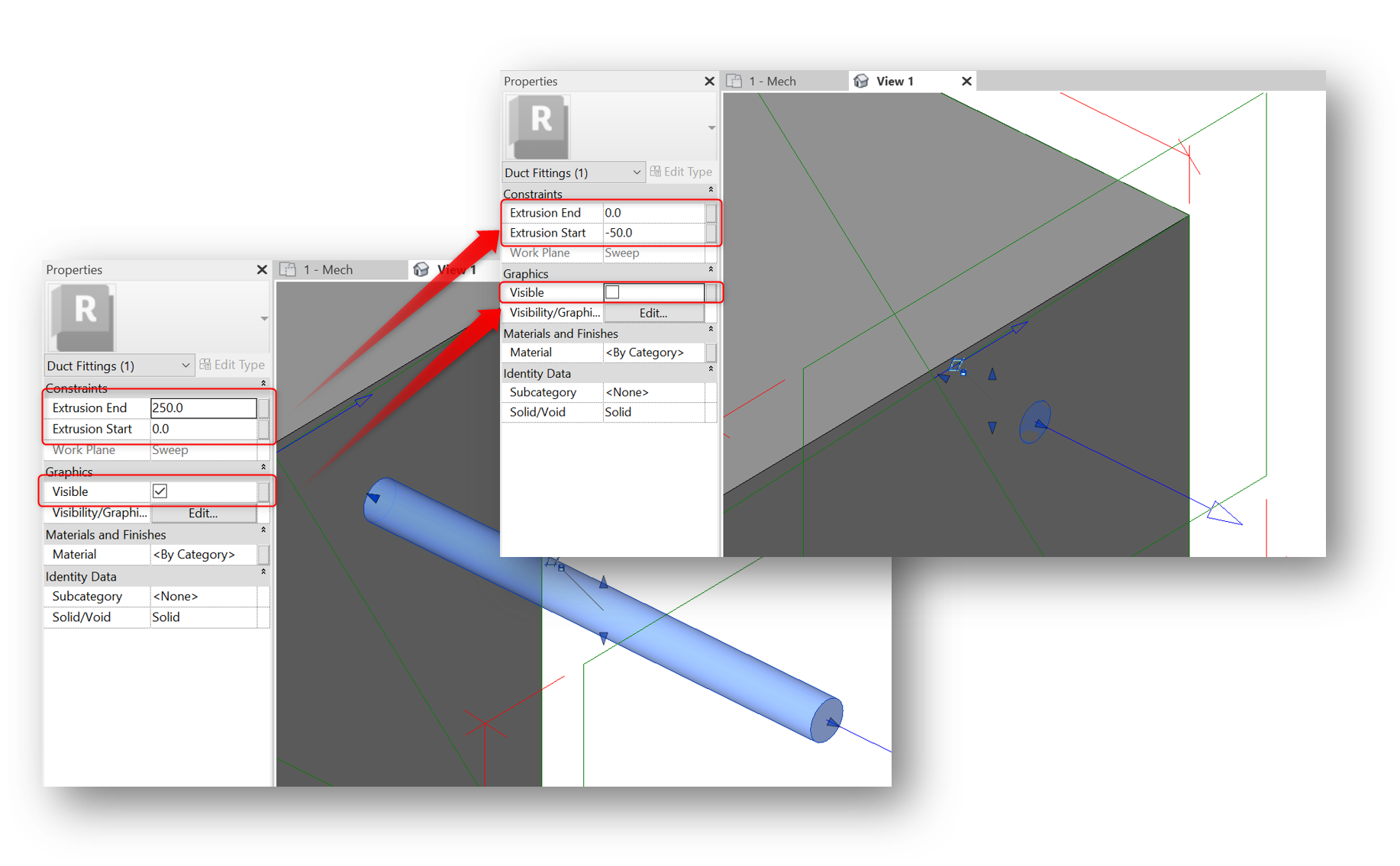
  1. Select extrusion > change Extrusion End/Start and uncheck Visibility.
image.png
By moving extrusion, we can change connector position (additionally there can be attached dimensions do extrusion).
  1. Go to Modify tab > Load into Project.

Products:

Revit;


Was this information helpful?


Need help? Ask the Autodesk Assistant!

The Assistant can help you find answers or contact an agent.


What level of support do you have?

Different subscription plans provide distinct categories of support. Find out the level of support for your plan.

View levels of support