
In this section, you will learn to navigate and select elements, use levels and grids to help to define project context and organize the design, and create floors, roofs, and ceilings by sketching boundaries.
Part one includes: About navigation, About selecting elements, About levels and grids
Part two includes: About sketching, Additional resources
About navigation
You can use the mouse to navigate around any open view. In 3D views, you can use the mouse as well as the ViewCube to navigate around a 3D view. To create a default 3D view, click the Default 3D view button located at the top of the Revit ribbon.

Exercise files:
N/A
Estimated time to complete topic:
3 minutes
Topic steps:
6
1. To pan the view, use the middle mouse button.
2. To zoom in and out, scroll the mouse wheel. The position of the mouse pointer establishes the center of the zoom.
3. To orbit the model in a 3D view, press Shift + middle mouse button. If you select an object and orbit the view, the selected object is the center of rotation.
4. To orientate the model to a predefined position, select a face, edge, or corner on the ViewCube.
5. To reorientate the model, click and drag the View Cube.
6. To open additional views of the model, from the Project Browser, double click the view name to open the view.
About selecting elements
The modify tool is used to select elements and sets of elements in a model. Modify is the default active tool and the first tool on every ribbon. When the cursor displays as an arrow, the modify tool is active, and you can select model elements.
Exercise files:
N/A
Estimated time to complete topic:
3 minutes
Topic steps:
7
1. To end a tool or deselect any selected elements, click Modify, press Esc, or click on a blank spot in the drawing area.
2. To select an element, move the cursor over the edge of an element to highlight it and click to select it.
3. To add elements to a selection set, press and hold CTRL while clicking on the element.
4. To remove elements from a selection set, press and hold Shift while clicking on the element.
5. To cycle through possible selection candidates near the cursor, press TAB.
6. To select elements using a crossing window, click and drag from right to left. Any elements entirely inside or crossing the window will be selected.
7. To select elements using a containing window, click and drag from left to right. Any elements entirely inside the window will be selected.
About levels and grids
Levels and grids help to define project context and organize the design.
Exercise Files:
N/A
Estimated Time to Complete Topic:
10 minutes
Topic Steps:
16
Placing levels
Levels define floor levels of a building or other important datums like the top of a foundation or the roof plate height.
1. To place a level, first open an elevation or section view.
2. On the Architecture ribbon, in the Datum panel, click Level. If the tool is unavailable, make sure an elevation or section view is the current open view.

3. Left click in the drawing area to define the first end of the level.
4. Left click in the drawing area to define the second end of the level.
5. Click Modify to end the command.
6. Select the level and adjust the Elevation and Name in the Properties palette.
Creating grids
You can use grid lines to help plan the building layout. A grid is a type of datum element, a non-physical item that is used to establish project context. They help maintain the project horizontally. They consist of a series of lines along with bubbles that contain the grid name.
1. To place a grid, on the Architectural ribbon in the Datum panel, click Grid.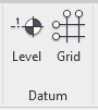
2. On the contextual ribbon in the Draw gallery, select the Line tool.
3. To specify the grid start point, click in the drawing area.
4. To constrain the grid placement to horizontal or vertical, press SHIFT.
5. To specify the grid end point, click in the drawing area.
6. When creating a grid parallel to another grid, a listening dimension appears. After the grid is created, a temporary dimension appears. Click the temporary dimension value to activate it.
7. Enter a new value and press ENTER.
8. To create large grid layouts, use the Copy and/or Array tools.
9. Click Modify to end the command.
10. Select the grid and adjust the Name in the Properties palette.
Ready for more? Head to Tools & functions part two for: About Sketching, Additional Resources
Or go back to the AEC Collection Quick Start Guide for Contractors
