Description
Key Learnings
- Learn how to configure and apply plastic rules to a design, then how to interpret the design advice for a part.
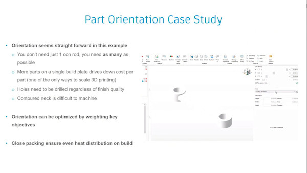
- Learn how to add common plastic features to a part, such as snaps and bosses.
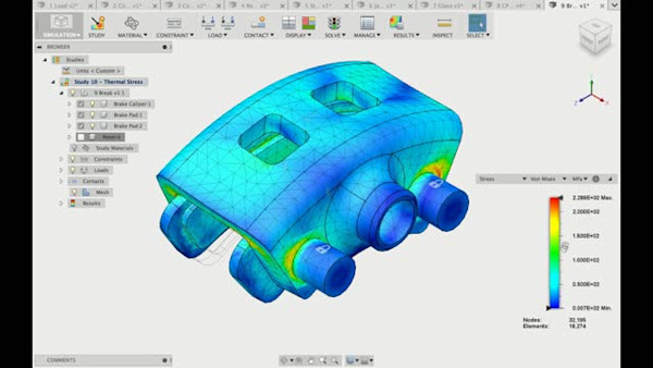
- Learn how to analyze a snap design for performance, including deformation during engagement.
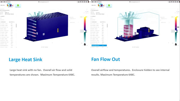
- Learn how to determine the mold-filling characteristics for a part.
Speaker
- JSJim SwainI am an Applications Consultant with Synergis Technologies LLC, specializing in mechanical design and analysis. I hold certifications in AutoCAD, Inventor and Fusion 360, and am an Autodesk Certified Instructor (ACI). One of the most rewarding results of this is that I am active in the Autodesk Learning Partner program, where I teach and support Fusion 360 in the educational community. I have B.S. and M.S. degrees in Mechanical Engineering from Lehigh University, where I started my CAD/CAE applications career path. I have worked with a variety of CAD and CAE tools in the automotive and consumer electronics industries as a design engineer, a CAD manager, and a trainer. In addition to implementing CAD at these companies I co-developed an in-house course on designing parts for injection molding. For the past 26 years, I've worked at Synergis, an Autodesk reseller in the Mid-Atlantic region. There I've conducted training, implementations, and consulting with various Autodesk products, including AutoCAD, AutoCAD Electrical, AutoCAD Mechanical, Inventor, Fusion 360, FEA and CFD analysis tools. I especially enjoy helping others learn tools that help in their jobs, and have had the great fortune of speaking at our annual learning event, Synergis University, at Autodesk University, and at the college level during my career.
JIM SWAIN: Hello and welcome to How to Design Plastic Parts More Effectively Using Autodesk Fusion 360. My name is Jim Swain. I'm an applications consultant with Synergis Technologies.
A little bit about myself, I've been with Synergis for 25 years now, technical end of things, doing training, support, implementation, a little bit of pre-sales as well, but the whole gamut of the technical, long time Inventor user from when it came out, longer time AutoCAD user, and started picking up Fusion for real a few years back. I wanted to try something a little bit different.
I love the simulation tools in it and the simplification tools that lead into simulation. And that was really the hook that got me started. Prior to working at Synergis, I was a design engineer, test engineer, CAD administrator for a couple of different companies, a company called Lutron Electronics, consumer electronics. And between that and my main hobby of model railroading-- despite the antique car sitting there, model railroading got me started on the plastic part design.
So heavily into plastics when I was at Lutron. Prior to that, I was a test engineer and a CAD administrator at Mack Trucks, heavy duty, on-road vehicles, off-road vehicles, that kind of thing. Not a big move into Lutron from Mack, it was by necessity.
I've been using CAD since 1982. I was part of a group that actually physically moved devices into the mechanical engineering department at Lehigh University, where I got my mechanical engineering degree. So long time CAD user is really what it boils down to. I've been enjoying Fusion. I find it a very fun software.
For a while, I found it frustrating because I kept trying to run it just like Inventor. And it's not the same beast. It's got some different workflows and such. Inventor had tools to help with doing plastic part design for quite a while. And now I've got similar tools in Fusion. And that's what we're going to be using here.
So with that, today's learning objectives are learn how to configure and apply plastic rules to a design, then how to interpret the design advice for that given part. Learn how to add common plastic features such as snaps, screw bosses, things that you typically use for assembling pieces together, to make your final design. Learn how to analyze something, like a snap design, for performance.
That includes while the snap is being engaged not just the actual molding of it. But is it going to be strong enough? And finally, learn how to determine the mold filling characteristics for a part.
Now, that's the order I have them listed here. But you're going to see that they blend together so that I can't really separate, say, the mold filling capabilities from the stack performance. They all kind of come together.
Now, a couple of things before I dive into it. First of all, saying injection molded plastic parts all the time is just a lot of syllables. So I will typically say things like, well, plastic part. And that implies an injection molded plastic part. So be aware of that.
Let's take a look at some of the overall plastic challenges that, well, they come when designing plastic parts. Typically, when you design an injection molded plastic part, you're pushing hot resin into a mold. It's cooling down. And then your final part's formed.
And while that cooling is taking place, the resin will shrink. It starts at some volume and then just collapses, pulls in on itself as the temperature goes down. That is the root of a lot of the challenges with designing plastic parts, not all of them, but a lot of things.
It can cause sink marks on the surface. So for instance, here you can see that I've got a thick boss, where maybe mounting screws come in, and, above that, an indication of sink because that plastic is going to cool longer. There's more plastic there. And it's going to sink in as the temperature comes down.
That can lead to molded-in stresses as well. It's going to start so big. And then it's going to try and go smaller. It's going to pull itself in. Right there you've got some stresses.
Differential cooling throughout different parts of the piece are going to add to that molded-in stress. Also, as it's shrinking, you've got the core of the mold coming up forming, say, the hollow on a piece like you see in the side there. And as the plastic shrinks, it's going to try and grab onto that core harder and harder the more it shrinks.
How do you get out of there? How do you make it so that it's not going to mess up any internal details that might be carved into the core? Also, as differential cooling takes place, what starts out as a flat piece, different parts are going to cool at different rates. You might get a little bit of twisting, a little bit of warping.
Sometimes it's not a little bit. Sometimes it's enough that you really have some problems, and you have to start tackling it. Other challenges, undercuts, the underside of a snap, the form that you've got the snap hook coming out-- something's got to happen to the mold. Otherwise, you can't get it out or else the mold goes up because of things like that. It's nice to be aware of it because you might have undercuts you weren't expecting.
Weld lines, these magenta lines here on the image. As the resin is coming in and filling the mold, it's going to come in. And if it hits something, maybe a piece of steel for forming a hole for a screw, or a boss, or something like that, or a web, or other channel, the flow is going to separate.
And then sooner or later, it's going to come back together. That's where the weld line is coming from. So from this point of view, it's coming back together. The challenge there is you can see it, depending on what's going on. You can also wonder whether that's going to be strong enough.
Is the world going to come together and mesh together nicely? Is it going to be hot enough that the material just flows within itself and just mixes well? Or is it going to be cold, and you really have two separate flow fronts coming in?
So knowledge of where those weld lines are going to be, you are going to have them. Knowledge of where they're going to be is important as well. Surface finish. Now, this can be tricky because on one hand, plastics are used for a lot of aesthetic pieces.
They can have textures on them. They can be highly polished. My lenses on my glasses, they're plastic. So you can have optical quality. A lot of times you're putting some kind of finish on there, a little bit of roughness, kind of helps hide the weld lines, hides the sink marks.
But also, the surface texture is really micro peaks and valleys. And if they're on the side of a piece, then those micros are going to try and prevent the part from being able to come off smoothly. And you have to take that into consideration.
Maybe instead of as quite a vertical wall, you go to more of an angled wall. --so issues that go on there that you want to consider early. Now, please note, Fusion 360 does not directly give you information on the molded-in stress. I'm not going to find that from this tool.
There are other tools, Moldflow Insight comes to mind, that can give you that kind of information, can simulate that. What I will get from the Fusion 360 simulation is the effects of the sink marks, the weld lines, that type of thing. In other words, will it work?
Will the plastic parts do what they're intended to do? Will they be strong enough? Will they have appropriate looks? Can it be made?
Can the plastic get in and fill the entire cavity? Or is it going to come up short and have a short shot? Can the mold be opened once you make it? Or are the undercuts going to give it some serious problems? That's all the type of things that we need to worry about early on in the design.
So how is Fusion going to help? Right off the bat, Fusion allows me to apply what's called a plastic rule. What that is going to do is it's going to keep track of what physical material you're going to be using. It's going to be nylon. It's going to be ABS. It's going to be polypropylene.
Also, various physical values that are going to be parameters that could be used in the design itself and some are automatically used in the design-- the wall thickness, I have it here as nominal wall thickness. That's a very common phrase in the industry as far as the way it shows up here in this image. It's the thickness.
This rule here, ABS, so the materials, ABS plastic-- and the nominal wall, 0.08 inches, typical draft angle. ABS, a good middle of the road plastic, I used it quite a bit where I was, used quite a bit in my hobbies as well, that and plain old styrene and also polycarbonate.
Recommended draft, 2 degrees, and that's from the resin manufacturer. What that means is the vertical wall isn't really vertical when I have about 2 degrees angle on it. And the reason for that, and I'll flip the angle on it, is if I try and have a vertical wall, the plastic, as it gets pulled out, is going to just smear along that.
It may not come out. I may have to hit it really hard. And it may deform the part as it's coming out. Whereas, if there is an angle to it, it's really a lift. It's a separate immediately. The 2 degrees is enough to overcome any inherent stickiness of the material.
Nominal radius. Here you can see it's half of what the wall thickness is. It's a design guideline. If we try and do any sharp corners, well, instead of sharp, we're going to have a little bit of a fillet in there to help guide the material around the corner so that it fills better.
You don't want to have a turbulence right there in the corner. It usually comes up with something that you can see the phrases like-- well, first of all, it could do sink but also blush. A little bit of disturbance comes out as a little bit of a change in the coloring of the plastic.
There are also values that are going to be used in the Design Advice Tool, thickness, range, and variation. How much are you going to allow the thickness to change before you want to flag? So here it's calling out 12 thousandths of an inch.
I'm also allowing a variation range of 40 thousandths to almost 120 thousandths, 118. And those are guidelines. The Design Advice will take a look. Hey, part of your design's exceeded this. You may want to take a look and do some redesign.
It's giving me a heads up early. Have I violated the minimum draft angle? Here you can see, in worst case scenarios-- get all the way down to a half a degree. That's pretty close to vertical.
If you blow that, you have red flags all over the place. Do some thinking. Do some rework.
Knife edge threshold. How small of a piece of steel are you going to end up with somewhere in your mold? Remember, any place where there is a gap in the plastic parts, there's going to be a piece of steel forming that gap. The resin is going to come and flow around it. And that steel is forming that gap that's in the later part.
Well, the problem is is your coming flow into it. You're hitting it with pressure as you push that resin through. And yeah, it can-- I do know of a mold we had that we had some blades in, real thin pieces of steel.
They were actually a maintenance item because they were fatiguing, because trying to form that little gap in the plastic meant a thin piece of steel. And it was hitting by the flow front. And it was being forced and relaxed, and forced and relaxed every time we ran a part. So it's something worth keeping an eye on.
I also mentioned the Design Advice. That is a separate tool that you can turn on. It's down under the Inspect dropdown, if you're running the Product and Design extension. That's where this information is going to be used and give you help to fix things.
Here's an example. Right now it's looking for thicknesses. I could ask for undercuts. I could ask for draft. I could ask for knife edges.
And then the thickness, I'm asking it, are there any areas of this design that are too thick? And yes, down where that one web meets the bottom, there's definitely some thick areas. So I need to give some thought to how I want to approach it.
In addition, Fusion 360 has some tools to just flat out help you put common plastic features into your design. What do I mean by that, as far as plastic features? Things like snaps.
There's a pair of them built into that long sidewall. You can see they're coming off the inside of that. And then there's that overhang as it comes out over that lip.
Bosses. Typically, I think of those as where I'm going to run a screw in for holding a circuit board in place or something along those lines. But they can also just be locating features, where to hold a circuit board while it's going to go through the rest of the assembly, other location type of things.
Ribs, webs. A web is just a collection of ribs. So I'm just pointing at one of them there. You can see how I've got ribs going off of three out of the four sides of those bosses. And, in fact, the middle of them are connected all the way across.
They're very common at stiffness. It adds, perhaps, a support feature, again, for a circuit board or a place where there's going to be a push button so that circuit board is not getting flexed too much underneath it.
I didn't highlight draft. Really every single surface on this piece that is not parallel to the top or the bottom, which are basically the flat, everything else has some angle to it. It needs draft, everything. You can't have a dead flat straight unless you're going to go and spend the money to not just have the mold be two pieces of steel that are opening up, but also having something comes in from the side to form that dead straight area or form the undercuts, for that matter.
So if you're trying to keep the cost down, everything needs to have draft. Trying to keep the speed that the piece can be run in the molding, which also keeps the costs down, everything needs to have draft. Within Fusion, in the core design area without anything added, there's a fair number of tools you should be aware of that are going to help you design plastic parts anyway.
There's the rib. There's the web, right underneath the Create dropdown. Under the Modify Shell, thin plastic parts, start with your full piece and then shell it to give the thickness of the area that the resin is going to fall through. Draft, apply draft to individual faces or groups of faces.
How do you group the piece? How do you tell it, oh, say, for instance, on my mouse that I want the parting line to fall along here. Well, that's going and splitting the faces that make up the piece or splitting an overall shape, an overall body, into two or more bodies, well, two at a time, to form different plastic parts such as the mouse body.
--then with the split body, separate parts, split face, separate faces that I can apply draft to. Excuse me a second. The third one there, Silhouette Split, is a very nice feature. Without it, things are much harder to work with.
From the viewing angle of the camera, this has a given shape. That's based on the viewing angle. Well, that also works out to be the extremes of the piece. That's going to be where I want the parting line when I design the mold.
That way the mold can open towards the camera, away from the camera. And that's the widest portion. It's called a Silhouette Split because if, for some reason, I needed to mold it in this direction, I've got a different shape. You see a different silhouette edge.
This is a tool that will apply curves to your body and allow you to design where that split's going to take place. And then over on the Inspect panel, we can take a look for Draft Analysis. That's a very quick tool.
We're looking for variations of color. Is there a spot where I'm seeing the color I don't want to see in that area? Similarly, Section Analysis, basically, slices through the piece and gives you a quick chance to look for any thick sections. This is different than the one they'll show you within the plastic tools, but still a useful tool. And there's also that minimum radius analysis that can come into play as well, as far as what that nominal radius is and then trying to avoid dead sharp corners, at least on the inside of the part.
The Product Design extension adds a whole new button at the top of the toolbar, Plastics. And specifically, it brings in the idea of the plastic rule. I can manage plastic rules, add new ones, edit existing ones, and then assign them to the different components within my design.
Over on the Create, not only is Rib and Web still there, but I've got Boss, implying screw bosses. But, as I said, they can be used for other things. Snap Fits and Rests. Rest is a flat with respect to which way the tool is opening when the part's getting molded.
And it's something that you might, again, just use as a rest, bottom side of a circuit board, holding something else that just needs to have a flat support behind it. This is a tool to help you design that quicker. And over on the Design Advice-- well, flip that around.
Over on the Inspect panel, there is Design Advice. So I can turn that on and have the software give me feedback on, how is my design going? Do I have any undercuts I wasn't expecting, [INAUDIBLE].
Do I have any thick sections that I wasn't expecting? Molding issues? Possible sync issues? Molded-in stress issues? Give me that feedback early so I can correct it right at the beginning of the design, before it gets too expensive to fix.
So let's take a look. All right. I'm going to start off of something called the enclosure. Right now all that has in it is a circuit board and its own component. What I'm going to do is quickly design a part around it.
So following rule one, let's make a new component before I do anything else. I can give it a name. It's going to be the bottom of the enclosure. So I'll just call it Bottom.
I'm not making it from existing bodies or anything like that. It's going to be an internal part. And it can be activated right away. So there's a new component, already active. And it's on the bottom.
First thing I'm going to do is go over to my Plastic tab. Now, if you don't have the Plastic tab, what you need to do is go out to the extensions and purchase the Product Design. Now, I say purchase, it probably should be air quotes, in that you have probably an amount of cloud credits or tokens, whichever mode you're in at the moment, that you can apply towards using this, opening it up.
In my license, I get a day access at a time. And it costs me six tokens. I have a few tokens. I'm in pretty good shape. I'm not going to purchase it again because I'm still in the middle of my one-day period.
Other licenses might have other setups for it. It could be a 30-day license. I believe the education market gets something along those lines. I'm not positive on that. Since I've kicked into the plastic world, I even have icons for doing snaps and bosses. And over here is my assigned plastic part rule and manage.
I'll go into the manage first. So you can see, I've already got a library. This is what shipped with the software. --and some various thicknesses. To be honest, I added the ABS. I'm pretty sure I added ABS 0.08 to that. But it's effectively the same as the 1.5 millimeter.
If I want to see what the information is, click on the Expand. So there's the call out for the polycarbonate. There's material call out and the allowable information. In my design file, I've already used the ABS at least once. So what I can do is say I would like to assign it.
And I'm going to assign it to this component. I haven't done anything physically yet. And that's the right time to assign the plastic rule, before I start doing things that are then going to come back and ask for a shell thickness, or a web thickness, or things along those lines. Get the rule in early. Therefore, the parameters will be applied.
If you apply it later, it's not going to necessarily adapt any of the existing features or all of the existing features. They won't know about the parameter. It shows up in the browser under the plastic world. And there is the information.
If I want to change it, I can do that right here. So I can go ahead and assign that. And now you can see it's 0.080. These next few steps are going to be basic Fusion.
I'm going to go and put a sketch plane on. I'll use the xy plane of this component. Knowing what I'm going towards, I'll go ahead and project this entire circuit board outline. This is going to be a very quick and dirty design, not going to get very fancy about it.
At this point, I don't care whether it's a link or not. I would probably leave the link in place. That way, if the board changes shape, it'll come through. But I don't care for the purposes of this discussion. In fact, it's going to be as simple as that.
And I'm going to go and put some dimensions. Oh, I'll just do an eighth of an inch clearance. It might be a little bit tight. But I think you get the idea of where I'm going. And I'll even use that same value to drive these others.
I could be using parameters here and referring them back to the same parameter manually. I'm just doing it through the mention itself. No big concern one way or the other.
And in the real world, would I be lucky enough to get away with that? Probably not. But I can get away with it now because I'm doing this just for a presentation. And if I decide that maybe I want a little bit more, go ahead and tweak the value. Give just a little more clearance and so on.
So I'll finish my sketch, extrude it. Now, what I'm going to do for the extrusion is screwed everything. And I'm going to come down about a half inch. So I have to remember to put the 0.5 in there.
Now, on rare occasions, you will get lucky. And you can maybe get away with a taper angle on something like an extrusion, or a sweep, something like that, where if I put in a minus 5, you can see how that is sucking in the side of that. Negative values for taper angle makes the thing get smaller as the extrusion goes farther and farther. So I can get extreme on there. Positive values, nope, not looking to do that. So we'll just take it back to that minus 5 again. That's not always the case.
If I didn't think I was going to be that lucky or I just didn't have a straight edge, what I would be doing instead would be, at this stage, extruding it straight down and then later, as my design gets a little more formalized, coming back and applying draft. The advantage of doing this here, doing this early, is that the draft that I'm putting in here is going to be carried through to the inner wall when I go and do a shell command. So that's why I'm doing this.
And yep, it's going to be a new body. It's the first body in this piece. And if I take a look, physical material-- oh, sorry, wrong route. That would be applying a new physical material. But if I take a look at its existing properties, ABS plastics have automatically been applied.
All right. I'm going to temporarily turn off the display of the PC board. And oh, good thing I did that because I hadn't noticed when I did the extrusion that I hadn't also extruded those. I'm going to pick those up real fast. I'm going to be using those for placing bosses shortly. There we go, a nice, very boring plastic part.
Now, I want to include a corner round. So I can do that via the Fillet tool. And oops, I made the comment earlier that I've been using Inventor for quite a while. And there's a couple of places-- fillet actually isn't one of them.
There are a couple of places where some things that in Inventor are in Modify. And in Fusion, it's in Create. So that was a translation issue. I'm going to go ahead and pick those vertical edges, holding down the Control key while I'm doing it.
And I'm not going to use it here. But notice, it's got a parameter being specified there, nominal radius. So it's picking up that value. I'll show you those parameters in just a moment.
That's a starting point. Now, I want these a little bit bigger. I'm going to actually give this an override and say, I would like it to be an eighth of an inch. And there we go. Yeah, not bad, it's a first pass.
And, as I said, shell, there's the button for the shell. And notice, I go and tell it to remove that. It never asked me for the thickness. It drops a different parameter right there. And it's going in towards the center, which is fine for what I'm looking for. That's going to be the inner shell.
So those parameters-- go up and grab the Parameter button. Let's be honest. I don't have it memorized off the top of my head where the button is. There we go, Modify. Plastic rule, there's some parameters that it started putting in place. So that stuff is being done for me.
And then some of these are being used, not that one. Oh, then, there we go. The thickness is coming into play. It's coming directly from that. I'll go and put some bosses on their next.
Turn back on the circuit board. But I'm keeping the bottom as my active component. The bullseye is still right there. And I'm going to put a sketch. I'll grab that xy plane again. It's convenient for what I'm looking to do.
And this is very simple for where I'm going. I'm literally just going to project those four circles, making sure I get the circles not the quadrant points. And I'll turn that back off again just make life a little bit easier. I can see what's going on a little bit better.
And now I'll come over to the Boss. Now, for the Boss, first thing it wants me to do is pick a sketch point. So I'll grab the internals, center points of those holes. And let's get a little more visibility here.
Offset Position, I want these to be down 0.064. Notice how they pulled down from the xy plane. That's the thickness of my circuit board. So I can make an allowance for right here as I'm going.
As I said, they are often used for being screws run into them. So I want to make a ball so I can drive a screw into it and hold the circuit board in place. At this point, I get to pick and choose what size I want to go with.
You can see how, as I pick different things, different portions of the design update and adjust. I can control what kind of effect I want to have on the top or the bottom piece. And I'm only doing the bottom here.
I want to put a little bit of a countersink in there to help guide the screw in, make it a little easier for the folks that are doing it. Is the whole depth going to be some distance off of the bottom of the piece? Or is it going to be from the top?
Off from the bottom is nice because that way I've got control over how close that pin that's going to form the void in the plastic gets to the other side. So hopefully I avoid sink marks and blush, well, more blush in here, because of turbulence as the plastic flows through. --sink marks in here because notice that area is thicker than the wall next to it on either side of it.
Back when I designed plastic parts in AutoCAD, literally, I would draw a cross section and see what size circle I could put through here and how did the diameter of that circle compare to what the nominal radius was. That's how I checked my thickness rules. so here I have a much better tool able to get me working on it.
If I want fine control over those designs, here's the data. I'm not going to change any of this stuff today. But notice how a lot of these are being driven by parameters that are, again, being derived from that rule that I picked for the plastic rule. So that's helping keeping things together.
Oh, well, for the sake of argument, let's see. Let's go back up here. And I'll turn off the countersink, just go with the regular straight drill. I'm assuming that the screw coming in is going to have a little bit of a conical tip. And that should work.
I can also go and apply ribs to these. So I can say, on side two, I'd like to have ribs. How many ribs do I want to have off of each boss? What kind of angle do I want them to fill in? What's the starting angle so I can give a little bit of a kick appropriately?
And yes, I'm deliberately putting a knife edge in here. So you can see what goes on. Normally, I would go and tie that into the entire sidewall. I'm going to leave that little, thin sliver right there. So there has to be a thin sliver of steel in there. But I make it.
When you hear someone working with molds and you see a sliver of steel, it's assuming that the mold itself is going to be made of steel. But they can be made out of aluminum, steel, rapid prototype. They can be even plastic with some backing, enough to get the heat out of the resin so it cools.
When I say steel though, it's just a general term for the mold material itself. All right. I'll go with that choice. And now you can see that I've got four of those in there.
Similarly, I could go and build webs and that kind of thing. But I think, hopefully, that you're comfortable with that. That is nothing unique to the world of plastic. What I am going to do here, though, is one more set of features.
So I'm putting another sketch, same place. I'm projecting these two edges. And I'm going to apply a point. And let's see. Let's just lock it on to the midpoints there, just so it's nice and easy. There we go.
If I look at it-- finish the sketch, swing it around a little bit. I got some point sitting there. I already used points to put in these bosses. These new points are going to be putting in snap.
Now, the snap, right there, it's exactly wrong. So I need to do some changing on this as opposed to just accepting the way the bosses came in. Right off the bat, I need to swing these around, maybe 90 degrees should be good. OK. That looks like it worked out here.
This one is still wrong. So what I need to do is tell that one to be independent. The one is at 90. And this one's at 270. There we go.
Excuse me. I keep hitting the mic with my hand. Hopefully that's not too annoying for you folks. I don't exactly have control of the cough.
You can also see that the snap is only partially going down the wall there. So what I could do next is tell it that it's going to be going the full depth. So instead of Extend Type being Distance, I'm going to go to Next. And there it is.
Now it's tapering into that wall. It's flaring into that wall and meeting up with the bottom floor. The actual details of the snap itself, I'm not going to go into the theory of what angles to put in here, if you want to be able to remove it, and forces going on.
That's something that, yes, the software is putting the information in for you. You still need to calculate, or at best guesstimate, what you want in there for an angle for the pull off to try and get a reasonable feel if it's meant to be disassembled. I've only been working with a single piece here at this point. But if I was working a pair of them, the mating part would have a groove or could have a groove for that snap to go into.
I'm going to say OK here. And there's my snaps. Now, remember, I put them in with the point right on the inner edge of the wall. I could have had the point somewhere else if I wanted to have it halfway through the thickness or something along those lines. It was picking up my sketch point.
So I've worked it. I've applied the design rule. I've added some design stuff. Is this any good? Well, let's go find out. Design Advice. When you start asking for design advice, the first thing it's asking for is the solid body. Well, there it is.
Second thing it's asking for is for a poll direction. It's going to use that to figure out if there are any undercuts. And I'm going to be pulling. I really don't care which way is up, which way is down. I'm not quite sure why they worry about that because the mold's going both ways.
I just need to give it a flat surface that the movement is going to be perpendicular to that flat. I'm asking it to find information on thicknesses, undercuts, drafts, knife edges. I'll analyze. Yeah, I got problems. And I can go and either scroll through this list here to get a quick look at it, or I can look at individual areas.
There's a lot of thick sections. I'm violating the allowable variation going on. Do I have any too thick? Actually, no. I'm sorry. I phrased that exactly opposite. There's a lot of variation going on. But what I do have are some areas that are going to be too thin to push the resin in.
The resins can be very viscous, like pushing honey. And it's not going to necessarily want to go in all the little nooks and crannies that you're expecting it to. That'll change resin to resin. Different ones have different challenges there. But it's letting me know that there are some areas that, with ABS, there's going to be problems.
I can also go take a look. Yeah, there's undercuts underneath those hooks, just where I expected them. But I don't have any unknown undercuts. Yes, it's a very blocky representation. That's fine.
If you're not sure where they are, click on it and it will highlight. If you're OK with any of these alerts-- yeah, I know it's there. We're OK with it. You can ignore it.
Draft. We got some very straight sides on that and very straight sides on the center of those bosses. That was that advanced section where I could go in and tweak the angle of the sides of the faces of the snap or the pin that's going in to form that. Otherwise, it's going to be a joy to work with.
And then, like I said, areas where I've got thin steel-- again, these are things to help you early find out what's going on, deal with them then. Check it frequently. And then go back later and check it again. Moving on. Back to-- I was there. Here we go.
Simulating the molding in. Now, this is an actual simulation. The Design Advice, that's live. That's almost instantaneous. This is more running a simulation to see how the mold is going to fill.
So you're given a material and its material properties. Rheology, I guess, is the fancy word for it. But how is the resin going to flow under certain pressures and temperatures, certain thicknesses for it? What kind of shearing is going to go on, where it's just going to get stuck to the walls and you're going to have to push harder, and harder, and harder?
Where are we going to put the injection gates? On this one that I've got the picture of, there's a single spot where the resin is getting forced into the mold, right there, that cone. And that is an ideal gate. I don't have control over the gate shape or anything. I'm just saying it's there. Whatever the material is it's the perfect gate for that material.
Injection mold process parameters. How warm is the mold? How warm is the resin going in? That kind of information, you're given some basic values to start with. Each resin has its own range of values and a default starting point.
Now, my personal opinion, stay with the default as long as you can because some of those design issues that are going to come up that we're going to see are suggested to be fixed by maybe increasing the mold temperature, or injecting quicker, or things along those lines. I'm going to try and get my designs, when I can, to be working at those default values because that doesn't give a scrunched down processing window for the molder.
That gives the molder as wide a window as possible. Therefore, they should be able to make parts easier. Therefore, the price should be less. A lot of therefores-- given that information, I was looking to fill.
Where am I likely to see visual defects, sink marks, weld lines? How likely is it to warp? You can get two different types of result. Guided results, similar to what we were seeing before, hey, here, there's going to be an issue. But they also give suggestions for ways it might be fixed.
It could be geometry changes. Make it thicker, make the plastic part thicker. Make it thinner. It could be process change. Raise the mold temperature. Raise the injection temperature, things along those lines. --giving ideas, guidance, on how you might be able to fix what are potential problems.
Fix them early before you start actually making the mold. Then you'll have more full bodied results. It's running a Pack and Fill. It's Fill and Pack. I said that one backwards.
So the resin is getting filled into the mold. And then the pressure is held to pack the resin in as much as it can. Then the cooling starts. Based on that, what are you going to have as far as likely warp? What are you going to have as far as likely areas that are going to cause an issue?
Let's take a look at-- well, I'm not going to look at that quite yet. I also have molding process results. This is, again, aimed at the person that's running the molding machine. And it's going to be suggestions on speeding up the fill or raising temperatures, things along those lines.
Again, my personal philosophy, try and stay with default values and get your design to work with default values so that the person running the mold has as wide of a process window as possible. Also, you can go and take a look at the results of two different studies. What happens if we use two gates instead of one or three gates instead of two?
Where do the weld lines go? Do we fill it fast enough? Does everything fill? Or what were the temperatures? And what were the pressures? So the same-- the same part and the same mold but two different sets of results get a feel for, well, there's the weld line.
What's the temperature like when the flow fronts at that weld line location? --to get a feel for a couple of things going on. Now let's take a look at it. So this is going to be looking at existing results for an injection molding simulation that I've already done.
We'll take a look at a bad design example. There we go. And let me finish the results so you have an idea of what's going on here. What I did here was I designed a part about as hideous as I could think of.
We've got thin areas that are feeding thick areas. We've got dimples sticking pretty far into the piece. We've got some nice tall bosses. We've got some real thin areas here. Let's see how it molds.
Basic molding setup, work your way from the left to the right. I didn't have to simplify anything. Molded-in lettering, I might simplify just to get the early analysis quickly. Target body, yeah, there's only one. Let's go with the ABS.
Boundary conditions, where is my injection location? Are there any faces that I want to treat as aesthetic? Meaning, or am I going to get sink marks on the aesthetic faces? Am I going to work with the process settings and mess with those at all?
And there's the summary of my setup, one injection location, one aesthetic face. It's on the back side here. Injection temperatures, again, automatic stuff. I could hit Solve Here. I'm not going to. I've already a got solution to it.
Be careful, by the way, if you make any changes, it will start flagging the results as invalid because it thinks something has changed. Green check, yep, it's got everything it needs. I can go ahead and run it. But, like I said, I already did run it.
So go down to the results. And what I've got here is the guided results, things like, a little bit of this part's not going to fill. I'm going to get a short shot. Yeah, the tip of that blade, that one might fill. It might not.
This one, I don't think I have a hope of getting resin in there. But it's too thin. The resin is too viscous. It's not going to get in there. It might be too cold by the time it gets in there. So that's going to be an issue. I'm going to have a short shot.
Warpage, those corners are going to warp. Yeah, I'm injecting here. But these corners out here, long, flat areas, they're going to-- there's a good chance of potato chipping. There's probably a better term for it. But it's the one I like.
Visual defects. One out of the one aesthetic face will have sink marks. And you don't really see them here. But what it's getting at are these darker patches. Here's where a sink mark, it's got a chance of occurring. Here's where a weld line is.
If you notice, it's following where the thickness of the piece changes. It gets much thicker. We'll go there. As I said, warpage already. That's the guided result. I can go then and, oh, let's see, take a look at the visualization.
Yeah, I can't say I'm really seeing anything here. I'm looking to see if there is any deformation, any facets that are a little bit darker compared to the rest. Unfortunately, it doesn't show up on this one. The full blown display-- let's get back over to the other side here. Yeah, that'll work.
Fill Time. So here's, kind of, stepping back in time as the plastic comes in. Here's how it's approaching. And you notice-- I was talking about separating in the flow front. There's an example. We're separating as it goes around those dimples.
And now it's also separated. There's some coming in, filling in this. I've got two different thicknesses here. That's getting nasty. These haven't even started to fill yet.
They don't fill towards way close to the end so the resin has a chance of cooling. So you might want to take a look at the cooling going on. That was fill. And yeah, there's a Play button. So I don't have to drag that, just go ahead and show it. Leave that looping while I go get coffee or something along those lines.
Confidence of fill. Yep. No confidence at all that that part there is going to get any plastic in it. And which pressure is going to be used? And you see that little pause. That's normal while it loads up the results,
3,000 PSI, 1 and 1/2 tons of injection pressure. And you're pretty much down to nothing here. There's no more oomph getting the plastic in that area by the time it gets there.
Flow Front Temperature. Those weld lines, how hot is it where those weld lines were going to be? And they're really in pretty good shape. It stays pretty warm throughout. So on, and so on, and so on through the classic types of information.
Oh, gee, it looks like we're going to trap air in there. So we need to put a vent in there for the mold. Molding process, it's that other one I was showing you there. And then, as I said, I can go and compare.
Right now it's injection, looking at air traps. Let's do fill animation on this one and air traps. They are going to be linked together. They are synchronized. And hit Play. So the view is synchronized. If I change the view at all, I'll see it take place.
Yep, that's how it's filling. And you see what's left. In addition to the molding analysis, one of the other things that comes into play is, will it do its job? So is it going to be strong enough?
Molding gets me half of the way there, comfortable whether or not I can make it. Will it do its job afterwards? And that boils down to running the more traditional Fusion simulations.
Static stress is holding things. How strong is it going to be? Is the design going to work? Dynamic or quasi-static? When I go to snap this together, is it going to be able to-- well, how high am I going to stress it during the snapping? Let's take a look at that.
So there's my snap. And what do we have up here at the top? There's the dynamic event. The difference between the dynamic event and a quasi-static is a dynamic event cares about inertia. What's the momentum of this piece as it goes along, of the impact or something like that?
For snapping, especially for plastics, they're so lightweight. I don't care about the momentum. So instead, I would use what's called quasi-static. I'm still looking as a time event.
All right. It's coming in. It's coming in. It's pushing that up. And then it's snapping through. OK, it's a time event. But I'm not worried about the inertia of this thing flying up and coming back down. I'm assuming that they're so lightweight that it's not going to try and keep flying off on its own.
I ran the event on this, ran the analysis. And you can see that, as this is moving along, we've got some high stress here. In fact, I really do need to tackle this. Steel would be deforming at that level of stress, let alone ABS plastic or nylon. I did nylon on this.
Now, it's only lasting for the amount of time it takes to snap it. But that high stress level could easily be enough that the nylon snap is going to take a permanent set and stay down there. One of the biggest challenges with plastics is getting good high end material properties. How much stress can this hold for how long?
My approach was if I can get it, great. But if I can't, I'm going to go with what's published for strength on it and go from there. And, at least that way, I'm somewhat safe. So what we've done in here was take a look at an overall design process.
We started with the basic shapes and how I can build a model that includes common plastic part features, snaps, bosses, allowances for the resin, the plastic rule assigning the resin. Remember, assign the rule right off the bat. The rule is also then coming into play for things like the wall thickness on the shell and so on.
So I can build my plastic parts faster and using values that I can count on. I'm not going to forget that nominal wall because it's coming right in from the plastic rule. And therefore, I can get there quicker. Then I've also got the Design Advice to come out and check to see if I'm doing anything unintentionally wrong.
Finally, I can take a look at it and see if I can mold it. If I can't mold it, why bother going further. Fix the design so it can be molded. And if it can be molded, is it going to do its job in the end? Will it be strong enough in this case?
So that is designing plastic parts better using the tools within Fusion 360 and the product design extension. Thank you very much for your time.
Downloads
Tags
Product | |
Industries | |
Topics |