説明
主な学習内容
- Learn why you would want to use Inventor as your primary design tool, but Autodesk Fusion 360 for electronics design and manufacturing.
- Learn how to apply simple iLogic rules to make use of iCopy functionality in Inventor.
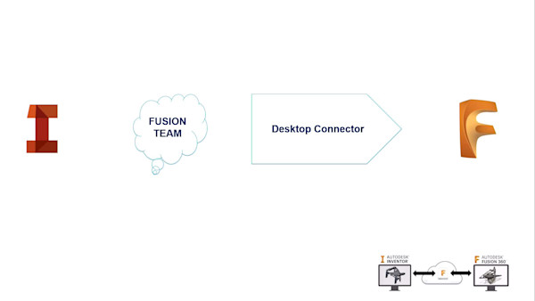
- Learn how to integrate Autodesk Fusion 360 into your Inventor workflows while still maintaining associativity.
- Learn how to create a PCB in Autodesk Fusion 360, driven from Inventor geometry, then include the PCB in your final Inventor assembly design.
スピーカー
- Scott MoyseScott Moyse is the RevOps Manager at Toolpath, where he focuses on enhancing operational efficiency and driving growth through strategic process optimization and data-driven decision-making. In his current role, Scott is dedicated to aligning sales, marketing, and customer success operations to ensure seamless and scalable business operations. Before joining Toolpath, Scott was the Product and Platform Manager at Cadpro in New Zealand. Scott played a crucial role in managing and optimizing internal business systems, platform integrations and working closely with the marketing team to launch Cadpro’s new brand and digital presence. For the majority of his nearly 11 years at Cadpro, he worked as part of the technical team, specialising in Autodesk’s manufacturing-focused design and engineering products. With a particular focus on CAM solutions, which included supporting customers across New Zealand and Australia. He also developed Post Processors for Fusion, HSMWorks, and Inventor CAM, and created add-ins for Fusion. Scott’s career began at SMI, where he spent over 9 years after relocating from the UK while studying Motorsport Engineering. He started in design support and quickly moved into programming CNC machines. Over the next 4 years, he collaborated with manufacturing and design teams to develop and implement automated processes, gaining deep insights into both departments. In 2008, Scott transitioned back to design full-time and was promoted to Design Manager in 2009. He successfully implemented and managed Autodesk Vault Professional, which improved communication, work allocation, organization, and control over the design review process. His experience in process formation and development in evolving environments was pivotal during this time. Outside of work, Scott enjoys spending time with his family, designing Grumpy Sloth low-profile mechanical keyboards, watching Formula One and running challenging trail distances.
SCOTT MOYSE: Hey. Thanks for your time today and watching this class. Hopefully you'll gain some value and understanding how Inventor and Fusion 360 can coexist together and how we achieved that and took advantage of both products at Grumpy Sloth.
So my handout will cover a bunch of the content that I discuss today in more detail, including a structured approach to these learning objectives. But you might be wondering who I am and what do I know to be able to comment on this sort of topic. I spent nine years using Inventor and Autodesk Vault in the super yacht industry designing super yacht interiors. And I first started using Fusion 360 when it was an Autodesk lab tool back in 2007.
For the last nine years, I've spent working for a reseller called CAD Pro systems in New Zealand. And I've been working as a technical specialist predominantly with Inventor in Fusion 360. I've done a lot of stuff with Vault Pro and a heap of stuff with CAM in recent years. For the last two years, or two years ago, we decided to start Grumpy Sloth, and I've been a contributor and lead designer on that project.
This is just a quick snapshot of the type of work that I did with Inventor-- so quite involved, a lot of detail, and lots of different manufacturing techniques, lots of communication with stakeholders. And I come at a design approach based on that experience.
And so here, we've got some renderings of the keyboard we prototyped in Fusion 360. So the whole process started two years ago using Fusion 360. And we've gone on to remodel this for production in Inventor.
Now, the experience of modeling the same thing in two different products was enlightening and reminded me of why Inventor is such a great CAD tool. So Fusion 360 is fundamentally brilliant as an ideation concept or industrial design tool, but it's lacking in areas where Inventor is just delightful to use. And so I intend to show you some of these things as I tell you our story today.
So the primary question we want to answer here is, should I use Inventor or Fusion 360? And to achieve that through this presentation, I'm going to cover off the purpose, process, and payoff. And so purpose-- which Autodesk CAD/CAM tool should I use? When should I use them? And how should I apply them?
The process we're going to use to achieve that is cover off some real-world examples and compare functionality to justify the use of each individual tool and how they can be integrated together. The end result is going to be productivity gains and the higher level of detail in each respective tool in their area of strength, overall creating more information and data, creating a better product for production at the end of it.
So what is a keyboard? Well, fundamentally, it's an ergonomic case with keycaps, contains electronics, and it's got an electromechanical interface so that us humans can communicate with a computer. And then there's some wiring involved, both internal and external. Overall, it needs to be functional, attractive, and comfortable to use because we all use keyboards for extended periods of time. And it needs to contain components in a safe and functional way.
So what makes a keyboard? Well, we go through a series of processes-- first of all, design. Then we need to manufacturer. Part of manufacturing is we also have to purchase product or components for manufacturing, but also then for assembly. And we have to communicate with various stakeholders. So I as a designer have been communicating with a machinist and also with a PCB electronics engineer in Turkey.
So digital prototyping-- we need to create a 3D model. I always say that design is split up into thirds-- modern design, at least. We've got 3D models a third of the time. And another third of the time is collecting information, and adding metadata to the 3D model, and storing that in a document management system of some kind. And then the last third is creating all of the documentation surrounding the product and communicate how to design and how to manufacture and assemble or repair the product.
So when should I use Fusion 360 instead of Inventor? Well, it's a really good R&D prototyping tool. So when we were coming up with ideas for different keycaps, it was brilliant. The surfacing tools are excellent and inside Fusion 360-- definitely better than they are in Inventor.
And then we get our analysis tools for checking curvature continuity across faces and curvature on a face. That's just far more superior than what's available inside Inventor. It looks better, and it's easier to use.
Then from an assembly standpoint, you can do everything inside one file. So with section views, you can very quickly establish motion and clearance. And just simple joints create check motion and a really intuitive and quick way without being burdened by the structure of building out nice assemblies for production.
So these were the machined prototypes of the keycaps. Although we love the SM kind of a low profile SA-style keycap on the right. We decided on the first keyboard we manufactured going with the keycaps on the left. And that design ethos is carried across into the case itself.
So the sculpt environment is phenomenal inside Fusion 360-- far, far better than what is available inside Inventor. And as you can see here, we can very quickly, using T-splined surfaces, generate a concept of a keycap profile. So we've got our T-splined surface, and I'm patching it off with B-rep surfaces, stitching it together into a solid, which means I can then apply a fillet to the outside of it.
And then, finally, shell out the underside of it to create what is effectively a keycap. Very quickly, in less than a minute, you end up with an idea in 3D. You can make some decisions based on that super fast.
So then Fusion 360 has an excellent electronics environment now, acquired through Eagle. And so the whole idea here is having an integrated 2D and 3D electronics environment. So you can create your schematics, your 2D PCB layer, and push all of that data through to a 3D PCB.
So you can check for interference and collisions between this assembly and the internals of your product. That might be that you need to move one of the components to free up some space. So here, I'm moving one of those electrical components. I then have to push that back to the 2D PCB, which will then update all the traces, sync that back to 3D, and you'll see the trace and the pads update.
Next up, getting on that basis that assemblies or simple assemblies are very quick and easy to build inside Fusion 360. Fixture design is excellent. So Bruce Burns, who's doing all the machining for this project, came up with the idea for this fixture for the keycaps, trying to cover off all of the different sizes, started off in the bottom left, transitioned through into the top right, and then finally the full assembly on a 4th axis Trunnion table and is 3 axis mill. So these are going into production as we speak.
So here, then the CAM as well. I'm not covering off any tool path generation here, but you can see these tool paths being simulated for both the first operation and then the second operation for these keycaps. Now, one of the things we did during the prototyping of these keycaps was adjust the profile of the face that your fingers are going to interact with to make sure that we could machine them with the side of the tool like this instead of 3D surfacing them. Here with 3D surfacing, the chamfer is to create that nice stepped effect you saw in the pictures earlier on.
Now we're machining the first side of the case itself, removing all of the material and then machining off that same detail that's on the keycap onto the case itself. So not only are we verifying the tool paths themselves and stock relative to the model that we've created, but we're also validating the motion of the machine and making sure that everything's going to clear throughout the whole process. We can check that things are going to look right because there's a difference between what you machine versus what you design. You can have raises and fillets left in the real world that you haven't included while you're designing.
So generative design is a big feature of Fusion 360. And while we haven't used any generative design on this keyboard, we may do in the future. I've got some pretty cool ideas that I'd love to get into down the line. And so here, we've got a DENSO ECU cover. And it's a great example of how generative design could be used on a component that's part of an electrical assembly.
So while it's not functional, sometimes these things don't have to be. Consumers love cool-looking stuff, and that's really cool. So I hope to have a cool generative keyboard in the future.
And then on the FEA side, there's a whole heap of studies that are available. We haven't needed to do any structural analysis of the keyboard. And hopefully, none of the components inside the keyboard get hot enough to need to do any cooling studies. But there's full integration with the electronics environment there as well-- things that just are not possible inside Inventor.
So when should I use Inventor instead of Fusion 360? Well, inventor's, what, over 20 years old now? And so there's a lot of mature commands and features inside the product. One of them that was really handy for this keyboard that wasn't available in Fusion is sketch patterns.
And so I've got this base skeletal model here with a series of sketches and planes which define the overall layout of the keyboard, and it propagates through all of the different components. And I've used my layout sketch to create a center point sketch, and there's a center point at the center of each individual switch position. I then use the sketch block for the footprint for those three holes. And I can then pattern that extrude feature based on all of those center points and very quickly get a whole heap of features punched through my PCB layout.
And the same thing for the switch plate. I just need to extrude the cutout for the switch to penetrate through. I can re-use that same center point sketch that's been derived through from my PCB.
But I need to specify a base point because this is a different z height to the PCB and make sure that extrude feature comes up to the right level. Straight away, we've got 108 cutouts. Now, that would have taken an awful lot of effort inside Fusion 360.
And later on in the process of designing, we realized that we needed to-- it would benefit CAM and the machining process to have the fillets modeled in the corners here-- not necessary but just helps things out. Now, to do this inside Fusion 360, I would have had to have selected four times 108 edges. Here, I can just roll back the timeline, pick the fillets on the first feature, and then apply that feature pattern across the entire switch plate.
And now we have a pattern feature inside a part when we switch across to the assembly. At the assembly level, the pattern command has a feature pattern option. So I can select the source component and then select a pattern feature from a component, and it will immediately recognize it.
That's real time. It just dumped all of those components into the assembly immediately. In Fusion, I'd have to place each and every one of those individually.
So Sketch Blocks is also a really nice additional feature inside Inventor that doesn't exist inside Fusion yet. For this sketch, for all of the stabilizer cutouts, I had to copy and paste each individual profile and continually manage editing each individual one if I wanted to make a change. Here, I've got an original source block. I want to get rid of these little arcs at the corners here because I don't want them to be filleted.
I can then close the profile back up using coincident constraints. And that propagates through to all of the other instances of that block. But because it's a block, I can copy as a single object. I don't have to select each individual sketch element. And then paste it and ideally position it accurately.
Here, I'm just loosely placing it either side of this switch cutout. And once we finish the sketch, can edit the extrusion and add those two new profiles. And again, any change I made to the original sketch block will now apply to these two new cutouts as well.
One of the unique things about Inventor as a CAD product at this level is its ingrained ability to apply tolerances to modeled features. So typically, you model to nominal sizes. But Inventor will allow you to apply the tolerance you've specified against a parameter to the model itself.
You can then extend that through to three annotations and product manufacturing information. So here, we're annotating all of our holes. We're specifying what the surface finish of certain faces or groups of faces need to be. And then you can apply these 3D dimensions to certain design views, which you'll see shortly can then be brought across into the 2D drawing environment.
Now, Fusion 360 as well as other competitive CAD products have the ability to read in all of this 3D annotation when you import an Inventor file. So Fusion, when you import an Inventor file for a particular method, it will then load up all of those 3D annotations if you specified a tolerance on a ball. And then in CAM, you use probing to measure that ball. It will take the tolerance information from the 3D annotation and apply it to that probing operation and make sure that, once you've machined the part in real life on the machine, when it's measured, it checks the SN spec as designated by the engineer who designed it. So again, a great example of Inventor and Fusion working together.
So here, we can see that I've got a drawing view placed as my case, and I'm able to retrieve my model dimensions. I can choose to include or exclude certain types of 3D annotation and base it off of presaved design views if I want to. I can then go through and manipulate the position of those annotations. Chang that they may have looked right in 3D space, but then in 2D space, they need some adjustment to suit. So at this point, they just appear like native annotations and dimensions inside the drawing environment, just as if you place them in here in the first place.
So that's a view of a finished sheet in the drawing. One feature of note here is that I only wanted to detail-- it says two plan views. But these faces here are a slightly different angle to the top faces, as you can see in the section view here. So the alignment of the holes wasn't quite right to be able to do a detailed view and dimension that like I have here.
So I placed another base view. But in Inventor, we can crop views down. So I've got two base views. One's cropped and scaled up and looking from a slightly different orientation just so I can get the correct dimensions for those features.
So we can do some design automation and configuration inside Inventor as well. And a part level fundamentally one area that's not available inside Fusion is feature suppression. So you can see these two groups of features in the bottom of my browser are suppressed.
They're driven based off of two parameters-- so Uwidth and Uheight. And that's a unitless parameter. And so keyboard keycaps are based on units-- so one unit being the size of just your standard square key.
As you increase the size of them generally over two units, you need to have stabilizers. And so these mains need to appear inside the model. And that applies to both horizontal or vertical keys.
So if we have a look at the feature properties, we can then see that we've got the ability to have a if statement for suppressing the features based on the value. So here, if it's greater than-- sorry-- less than two, then suppress the feature. We can also use sketch text to drive as a parameter. So we can use parameters to drive the value of the sketch text and have that impose itself on the model.
OK, so this animation of how the keyboard's disassembled. The keycaps come off, screws come out, then the PCB assembly comes out, and everything else comes out the inside of the assembly or the inside of the case. But the switches themselves come out at this point from the switch plate, and then the PCB comes off because the switches clip into the switch plate, penetrate through the PCB board, and then are soldered on. So we have to think about that process when we're designing and building up our assemblies and making sure the switches appear in the correct place that relates to how assembly is going to be put together.
So there's a whole host of BOM Structure settings available inside Inventor. So you set the default BOM Structure for a component in Document Settings-- so it'd that a part or an assembly. And you have five different choices, all used for different applications. And whatever that value is, you can override it to reference on an occurrence of the component inside an assembly if you need to.
So in this case, we needed to duplicate all of the switches at the top level of the assembly for iMates to work with the keycaps. So you will see that later on. But we don't want to double up the quantity of switches in the design and don't want them to add to the physical properties of the overall design.
So we set all of those occurrences of the switches to reference. And you can see that in the bill of materials on the right. We've got 108 quantity of the Kalh switches at this level, but they're all set to reference. So if we look at the Structured tab, they just wouldn't appear.
The stabilizers themselves are another great example of how we want to leverage these bond properties. So this assembly is something that's standard and fixed, which is used seven times in the keyboard. Now, we don't want to have to create it seven times of individual components to get the correct BOM structure for purchasing and assembly instruction purposes.
So we set the overall assembly as phantom in Document Settings. That means you can build the assembly once, but make sure it doesn't participate in the bill of materials structure. So this hides the assembly from the BOM and effectively promotes all of its children up one level in the BOM.
Then we have to stabilizer assembly itself. And we want the motion, so it needs to be an assembly of two parts. But it's a single part number when you purchase them, so they are set as purchased in the Document Settings. So it appears in the bill of materials is a single part instead of two.
And then we set-- and the stabilizer wire itself is left as normal. So we can see that here. So the result is two part numbers showing up in the BOM for the 24-millimeter stabilizer and wire assembly.
And because we did the same thing with the 76-millimeter variant of the stabilizer for the space bar, the total number of stabilizers for this entire assembly is 16 since they have been promoted from both phantom stabilizer assemblies. This data structure is now representative of how this assembly would be put together in real life. And currently, none of this is possible in Fusion 360.
Inventor's actually a really good product alongside Vault for internal and large-team collaboration, more so than Fusion 360, even though that's cloud connected. So each time you check in a file using Vault inside Inventor, it creates a new version. Whereas in Fusion 360, a new version is created every time you save.
So with Inventor, you can save locally on your own disk. Inventor has its own versioning ability, again, on disk. But when you check in, it's a controlled version being checked into Vault.
In addition to that, with Vault Pro, you can then lifecycle these designs and get revisions. So you can go from work in progress to release. And you'll see that an example of that later.
So here, I've checked out a drawing. I've applied some dimensions. Only I can modify this drawing because I'm the one that has it checked out.
My teammates are able to see the latest version in Vault, but not my version until I check it in now. Soon as I check it in, it's going to create a visualization file for it so that people who don't have Inventor can look at the drawing. And the rest of my teammates will then have my latest version of the drawing.
So BOM management-- sorry-- so data management relating to the BOM-- so we can go into-- this is Vault. I can right click on my top level assembly and create an item. When I switch to the bill of materials of that item, I can see that the first row is enabled. So that's the item that relates to the overall assembly. And I can drill down inside that bill of materials and start turning on additional rows.
Now, for my USB-C daughter board, I can see all of those components or individual line items that were visible inside the browser tree inside Fusion and turn on the ones I want selectively. So on the packages, there all of the electrical components which are soldered on to the PCB board. I want to make sure I turn all those on so they appear in my bill of materials.
There's some line items that represent the copper and solder mask. Ideally, they would be merged together into a single component with the board. But that's not how it's structured. So to work around that, we can just make sure we only turn on the board itself.
You can turn on all line items from the top level, which has just happened before. And now when we expand out the main PCB, we can see that everything's turned on. So we don't want the solder mask and copper to be included.
So we can use Control to select those and then turn them off. And none of these items have been created yet, and they won't be until I save this top level item. And it will go through and build out and create all of the child items at the same time for the ones that at least were turned on.
Now, one of the huge advantages of having the item master in Vault Professional is that we can include components which aren't in our 3D models. So you won't want to include things like grease, and oil, or spare parts package. You can build up those items separately inside Vault and then add them manually to this bill of materials. So that version of the bill of materials would only exist inside the Vault Professional Item Master.
And to reiterate that here, we can see on the left, we've got a view of the Inventor Assembly Browser. And we can see the 3D PCBs there. But when we go across to the middle image, that's a view in the Vault client of the files. And when you select the Assembly and have a look at the Uses tab, we can see all of the actual physical files that exist on disk.
And there is no physical file from 3D PCB. That's because it's been inserted from Fusion 360, and it's just cached inside the assembly as a graphics object with a whole heap of metadata and 3D graphics associated with it. But when you generate a item for that assembly, you'll then see all of that metadata get extracted from the assembly, and you now get to see a data representation of the 3D PCB and its subcomponents.
All right. So the next thing is lifecycling. So we've got this PCB blank. We're ready to send it off to-- we've just sent it off to the PCB Designer.
So we need to lock it down, make sure nobody changes it. But when we try and release it, it says that there's a rule that's stopping me because one of its dependent files, one of its referenced files isn't released. And we need to release everything at the same time.
So we can turn on the Child Components filter, and now we get to see all of its related files. And that then allows us to release all the entire data set in one go. So they've now been released for effectively manufacturing. So that means that area of the design is now locked down and can't be changed.
Inventor is inherently an excellent tool for large assembly designed. Fusion 368, at this point in its gestation, is still not great at it. And the very first point of contact or visible point or data point for performance for large assembly is just in opening the files. So here, we can see a comparison opening up the two top level assembly-- so the main assembly for the keyboard in both Inventor and Fusion.
Inventor gets the job done in 40 seconds, and Fusion takes just over a minute. And there's actually a lot more components inside the Inventor assembly because I've added more detail. I've added the key switches a number of times for various reasons. And so there's actually 2,000 component instances inside the Inventor assembly, and it's still opening a lot quicker.
Now we have Cable and Harness, and that's one of many design accelerators that are available inside Inventor for carrying out specific tasks. And specifically with cable and harness, it allows you to easily and meaningfully complete electrical designs of relevant metadata, including integration with AutoCAD Electrical, if need be. So if your BCP is part of a broader electrical system, then you can bring that in from Fusion, define electrical connections on the components, build out your connectors and then all of your wire and harness looms and plan out all of the wiring for your product. It's pretty simplistic for a keyboard, but we did have two molex connectors and a cable running between them, so I was able to define that properly inside Inventor, whereas in Fusion, it'd just be a sweep along the path, and the object wouldn't have any kind of electrical properties.
All right. So sending-- how do we send data from Inventor to Fusion 360? So first and foremost, when we send stuff over to Fusion, it needs to be loaded into projects in the Fusion Team site. And so projects give you the ability to control access to your data. And while we were collaborating with somebody in Turkey, we wanted to make sure that we created a PCB project just for all the PCB data, so he had everything he needed to be able to work but couldn't see the rest of our data or at least wasn't distracted by it or accidentally modify anything. So we created one project for PCBs and another one for machining.
All of these options on the screen then allow you to upload data into those projects. And so from 2023 onwards of Inventor, there's very specific individual workflows for pushing parts and assemblies into different areas of Fusion 360, depending what you're going to do. So whether you want to do some design, or subtractive milling, or turning, or additive 3D printing, or an FEA study or some generative design, it's really convenient. If you open the file at the same time as uploading it, it will create the Fusion design for you and set the workspace automatically based on the workflow you've chosen.
It will then add a URN-- effectively, the URL for the Fusion file into the-- embeds it into the Inventor file itself. But that means it requires the Inventor file to be read/write, which is a downside for some people using lifecycles in bulk because you can't release the file until you've pushed in to Fusion. But you get to choose the destination when you do this, so you can choose which project based-- as long as you've got access to it, you can choose which project and then the subfolders within it where you want it to be output.
So then you can also do this from Vault, and it can be automated via Lifecycle State change. It does send all referenced Inventor files, though, not just the file you're sending. So in the case of the PCB before when I released it, it would send the other two files there with it at the same time. And when it does that, it replicates the Vault folder structure inside Fusion Team. And that's actually really neat if you want to collaborate with another Inventor user who doesn't have access to your Vault but is data overload for these types of workflows where you just want somebody to work on machining a part or doing a PCB design.
Now, the destination or the destinations are preset. The Vault administrator can create multiple options for mapping, but you have to pick from a list. And from the browser, you can just navigate in Chrome to your team site, pick the project, pick the folder, and then use the Upload command. But assemblies aren't supported with this workflow. And it does give you good control over where you want things to end up though.
So I'm only going to cover the Send to Fusion from Inventor because that's the workflow we used. But here, we can see the switch plate. And I want to have it subtractively machined.
So I can then pick the location and the name of the file where I want it to be saved. I've chosen to launch Fusion 360 once the upload is complete. And I'm saving all of this data into the Inventor files folder of the Slim Sloth Machining Project.
Once it's uploaded, we can see the node which has been added to the browser that allows us to upload a new version later on if we want it directly from Inventor. It's opened up a Fusion design in the manufacturing workspace, so I can then add, set up, and start tool pathing straight away if I want. But if I bounce back to the Design Workspace, I can see this Component link, which has added been added to the timeline.
And that refers back to the Inventor IPT file that's been saved at the same time. And the file name of the design as copied is the same as the Inventor file. Now, I just want to move it out into the main Slim Sloth Machining Project because it's technically not an Inventor file since it's a Fusion design. And once I've done that, I can then go ahead and check in my design back into Vault and release it If I want, locking that data down.
All right. So closing the circuit, so what does around trip look like? So fundamentally, it's a four-step process. So for a PCB, we want to send it to the Modeling environment inside of Fusion. We then need to create a 3D board.
Either concurrently or after this, all of the electronics will get designed to the PCB-- the schematics, the whole lot. So we used a chap called Cem Sarlik on Fiverr. He's from Turkey. And absolutely amazing guy, did an incredible job. And in our specific case, we also need to make sure that the switch components were excluded from the 3D PCB for BOM reasons.
Once all that's done, we can then insert that back into Inventor by selecting the 3D PCB from the Fusion 360 drive that appears inside My Computer in Windows. So you do have to have the Design Connector-- sorry-- the Autodesk Desktop Connector installed, which, you can get the installer from your Fusion Team profile dropdown.
So this is what it looks like. We open up our 3D PCB blank, upload it to the team site. And we just need to create a sketch and project through the profile onto that sketch. If we turn off the bodies, we can then create an associative 3D PCB. Make sure the orientation is correct, and then save that out as a 3D PCB.
From there, we can link it to the 2D PCB and the schematics and push the 2D PCB data back into the 3D. And then suddenly, we can see all of our switches there. So we don't want those switches. But all the rest of the electrical components, we want to keep. So if we go back to the 2D PCB and push again, this time, we can use the Components search and filtering tools to display all of the key switches and then exclude all of those that are visible.
And when we get rid of that filter and have a look back through again, we can see there's a mixture of components that are enabled and disabled. And we completely come and remove the 3D component from the PCB. And now in Inventor, we can place imported CAD files, navigate to that 3D PCB through the Desktop Connector, and place the PCB as a reference.
So we're not converting it. We're referencing it, meaning that if there's a change, it'll get updated. And then we can joint it back into place into the correct location and check alignment and offsets. And I actually needed to change the gap here and change the type from Rotational to Rigid. And now everything's as it should be.
So this is Cem Sarlik's-- I'm probably not pronouncing his name properly. I apologize, Cem, if I've got it wrong. But yeah, here's his profile on Fiverr. I couldn't recommend him enough.
And the PCBs have actually been manufactured and on their way to us right now, at the time of this presentation. So the rest of the keyboard, hopefully, I'll have ready by the live session. And for those of you who are watching this virtually after the fact, I will do my best to get some photos of the finished product uploaded as part of the class after Autodesk University is completed. So yeah, it's been an excellent experience so far, and I can't wait to see this thing come to life.
So finally, there's some automation we can do inside Inventor. And the keycaps were-- there's 108 of them, and they're all different, but they're all very similar. So how do we go about minimizing the amount of time doing the same thing over and over again but just slightly different? How can we work smarter?
So iLogic and Macros, both available inside Inventor, can seem quite intimidating to begin with. But some super simple applications of the technology can make a big difference on an ad-hoc basis. And there's some really-- you just have to search around online a bit, find some code samples, copy and paste, and you can get some pretty basic results that have a big impact. And you'll see some examples of that here now.
So specifically with the keycap model, there's some conditional logic we need to apply. So we want to use the feature properties we've talked about before and apply conditional suppression. So we've got two different orientations for the stabilizer mounts if the keycap's over 2 units wide or high.
We've got unique legends. So we can create text parameters and have a value. And then if we insert that text parameter into our sketch text, then when we change the parameter, it will change the value of the sketch and, therefore, the extruded or embossed feature on our part.
So because it's a parameter, we can automate or drive the behavior of that if we want. Now, this is where we can start using some iLogic. So those sketch text parameters are going to change physically the key cap. But also, from a data standpoint, it needs to change it as well. So I want to make sure that each individual keycap has got a part number and a description, and it can be made unique based on those text parameters we add in-- so the top legend and the bottom legend.
So the first two lines of code you can see on screen here-- iProperties.Value-- 1 sets the part number based off of a prefix of OGS and then the parameter value and then the same thing for description. I could set up two rules for this, but it's pretty straightforward. I want to impact my property values, but I also want to modify the value of the stab offset parameter based on the value of the Uwidth parameter. So if the width of my keycap is above five units, then I want it to be 38 mils offset. Otherwise, I want it to be 12 mil.
How do we get this rule to run? Well, we can use it event triggers, and so you can apply event triggers across all documents for all of Inventor, or you can apply it to just a document. And in this case, we just got a keycap model. We only want this rule to run on that keycap, so we set the event trigger in this document. And the event I've chosen here is any user parameter change. So if any one of those parameters in this dialog on the right changes, then the iLogic rule will run, and we'll get the desired behavior.
So there's a command called Place iLogic Component. And when you execute that command and select a template, the Place iLogic Component dialog on the right will appear. And you can control what will appear in that dialogue based on which parameters have been ticked in the key column.
So we've got four things-- four parameters we want to control and vary on each placement of the key cap. And so I've ticked all of those. So we've got Uwidth, Uheight, Legend, and LegendLower.
But when we launch the Place iLogic Component command, we have to select the template each time. I don't want to select the same file 108 times. So we can create a macro to do that. And certain commands will accept a file path when you execute them. And fortunately, iLogic Place Component is one of those.
So just this few lines of code, I copied and paste, putting my custom path to my template, and then I bound that macro to a keyboard shortcut. So when I press Alt-I, will execute the Place ILogic command and pass it my template, so I don't have to keep selecting it every time. The other way we can speed up placement is we have to constrain each keycap to each switch. So we can use some composite iMates to do that.
And so there's three constraints required per keycap. So we can create a composite of the three, so we can have one object. Now, each iMate needs to have a compatible matched pair.
So on the underside of the switch, we can define a matching list and select the name of the matching mate on the switch. So we've got switch top is matched with underside in both directions. That's done for the other two Mates as well, and then it's all wrapped up into an a composite iMate.
But there's a caveat for composite iMates to work. The components of matching iMates have to be at the same assembly level. So all of my switches are inside my PCB assembly, not at the top level with my keycaps, which posed a problem. I couldn't place these keycaps in and have them find the iMates couldn't see them.
So I needed to duplicate the component pattern. So I placed the first switch again in the top left-hand corner, the Escape key. And I set the component occurrence to reference so that it didn't add to the quantity of switches in my bill of materials and didn't add to the weight or physical properties on my keyboard in any way, shape, or form.
I then created a component feature pattern, again, just like I showed you earlier, but at this top level and then turned the visibility of that pattern off. So it's just there for reference. it's the sole purpose of me being able to quickly mate all of my keycaps into place.
So this is the end result. So if I press Alt-I, I get the Place iLogic Component command. I can click OK on that dialog, left click to confirm placement. And then need to do the next one. I don't want to place the same one again, so I hit Escape, Alt-I.
This time, I change the width. That's 2, so it's going to add the stabs. I want it to say, Backspace, and I don't want a lower legend. Left click to place it, and it's just created another completely independent unique part file for me.
And repeat the process again, this time for the Insert keycap. Left click to confirm placement. Now, you can use the arrow keys to move around if you need to pick up on a different set of iMates.
But fortunately, for the most part, it does follow along linearly. Yeah, and that's it. So this significantly sped up the process of creating the keycaps compared to Fusion 360. I was literally there for days, whereas this took about 90 minutes, I think, to do all of them.
And that's it. So obviously, for this keyboard, we've leveraged both products-- Inventor and Fusion 360-- extensively in different ways. And as a result, the overall design process of the keyboards is far superior to what it would have been in Fusion 360 alone.
And we wouldn't be manufacturing it to the level that we are without using Fusion 360. So thanks, everyone, for your time today. And I hope you'll gain some value out of it, and have a good day.