00:08
Now that you've learned how to put schematics and panels
00:11
and your reporting tools all together in your project, let's
00:15
talk about customizing it.
00:17
If you need to make your own custom symbol, which
00:19
often happens, let's learn the tools that can get us there.
00:24
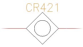
So let's take a really basic shape and turn it into a symbol
00:28
that we will want to use to make it electrically
00:30
intelligent and capable of doing everything
00:32
that you've seen thus far.
00:34
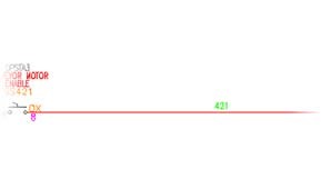
I'm going to zoom out on a rung that already exists.
00:38
I like to draw my symbols early this way so
00:41
that I can see the spacing of them
00:43
and how they look on a rung.
00:44
So we're going to go back to basic AutoCAD.
00:47
And I am going to insert a polygon.
00:52
I'm not going to use my object snaps.
00:54
I'm just going to use regular snaps.
00:56
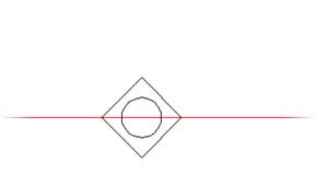
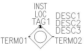
I'm going to choose four sides, the center of the polygon,
01:02
and make it inscribes.
01:08
And then we will put a circle right
01:10
in the middle of this one, really simple shape.
01:15
Now it may be that you're not drawing from scratch.
01:17
You perhaps have legacy blocks or other things from AutoCAD
01:21
that you want to bring forward into becoming electrically
01:27
We just need to bring them into our symbol builder
01:30
and you could automatically turn them from the regular AutoCAD
01:33
blocks you have into AutoCAD electrically
01:38
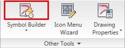
The symbol builder is located on the schematic tab
01:41
at the very end here.
01:45
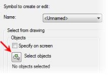
When I click on that, it's going to ask me a few questions.
01:48
First and foremost, select my objects.
01:51
If you didn't have any objects because you just
01:53
wanted to draw it right inside the symbol builder interface,
01:57
that's absolutely fine.
01:58
The symbol builder integrates into AutoCAD's block editor.
02:03
You can go in there to draw anything you want.
02:05
I just started out here so that I
02:07
could compare it to the other symbols that I have.
02:10
When I hit Enter, that now it becomes my preview.
02:13
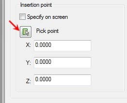
I could choose an insertion point now
02:15
or I can choose it later.
02:16
But if I click Pick point, I know
02:18
I want my insertion point to be centered on my object
02:21
and in line with where I will have the object break
02:24
the wires at the two ends.
02:27
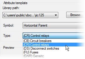
I also need to choose what type of symbol
02:28
this is, so I'm obviously going into the nfpa library
02:32
because that is what I've been using all along.
02:34
But then, I need to choose what I want my symbol to do.
02:37
Is it a horizontal parent, a horizontal child,
02:40
vertical parent, vertical child?
02:42
Remember, we typically have versions of both.
02:45
But if you never do vertical, don't
02:47
worry about building a second one, terminals or then even
02:51
your panel footprints nameplates or panel terminals.
02:55
In this case, I'm going to leave it as a horizontal parent.
02:58
And then I'm going to look at my attribute templates here .
03:01
Now this attribute templates are not
03:03
an exhaustive list of every type of component
03:06
we have in the software.
03:07
The generic covers that.
03:09
Generic is every attribute you might possibly
03:14
The rest of them have special unique setups
03:17
or spacing defined for how you would
03:19
want to define that symbol with the specific attributes needed
03:24
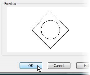
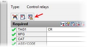
In this case, I'm going to make this a control relay.
03:28
When I click OK, I will then be taken into my block editor
03:33
Notice we are in block editor with that standard ribbon,
03:36
but then I can switch over to the other contextual tab
03:40
of the symbol builder between the block editor.
03:43
So both are contextual tabs that open whenever we
03:46
launch into the symbol builder.
03:49
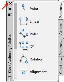
The most important part of the symbol builder is the pallet.
03:56
And I need to bring it over from another screen.
03:59
This I have actually set up if you've never
04:01
done this with an AutoCAD pilot, I have it set up to not dock.
04:05
So I have unchecked the docking .
04:07
And that's purpose so that I can purposeful.
04:09
So that I can set it on top of my project manager
04:13
without having it sinking to the screen
04:15
and take up even more real estate.
04:16
It doesn't matter which way you do it, though.
04:18
You're welcome to have it dock in right next to your project
04:23
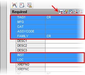
Now in here, I can see all of the required
04:26
attributes for this particular component type.
04:29
So again, this is our control relay,
04:31
so I want all of these attributes.
04:33
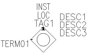
I am going to shift select to insert all of them
04:37
and click the little insert button.
04:39
They all come in at the exact same time.
04:41
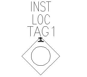
I just click to place them and they have the perfect setup
04:44
to exactly where I would want them especially in a control
04:47
relay so they can sit on one side of the bus lines
04:50
and then they're coming in stacked on top of that symbol,
04:54
very, very easy to set up and do.
04:56
This is the beauty of attribute templates.
04:59
If you are creating a lot of symbols and
05:02
you want to have attribute templates for you as well,
05:05
absolutely an easy thing to do.
05:07
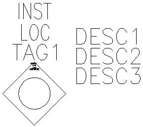
Attribute templates are just w blocks
05:09
of specifically the attributes without any geometry on them,
05:14
so that they can be inserted on top of your new geometry
05:17
just like I just did.
05:19
You could also have manually inserted each one of these
05:22
to put them wherever you wanted to.
05:24
The beauty of the attribute template
05:25
is simply the automatic insertion of all of those.
05:29
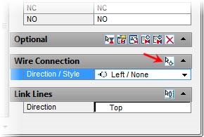
Now the last thing I need to do to make this fully intelligent
05:32
is allow it to know where wires connect
05:34
to it so that it can break the wires when it gets placed.
05:38
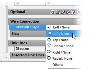
That is the wire connection area here.
05:40
Be cautious to click on it as opposed
05:43
to just assuming that all you get is a left or none.
05:47
You have to click to be able to see
05:49
that there are top options, bottom, right, radial,
05:54
Radial would be much like the motor wiring
05:57
that we saw before with the three phase wires that
05:59
automatically connect.
06:01
It is very important you choose which way the wire is going
06:04
to be entering this object because if you choose
06:07
the wrong thing for the location,
06:09
it will break the wire on the wrong side of it.
06:12
So for this case, I'm going to start with my left, click
06:15
Insert, and that's going to be inserted right
06:17
at the corner of my diamond.
06:21
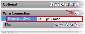
Now I want to flip this because I
06:22
don't need another left insert, I need a right.
06:24
So down at the bottom of my screen, I can choose right.
06:28
And then that will insert there.
06:30
I don't need any more terminals, so I can just end that command.
06:34
I now have wire connection points,
06:36
all of my attribute information, and it's an intelligent symbol.
06:40
Now you do not need to fill out anything
06:42
on the core functionality of these attributes
06:45
here because all of that happens in the Insert edit component
06:51
Unless you wanted a constant static insert here,
06:55
that would automatically come in every time as opposed
06:57
to filling it out in that dialogue box.
07:02
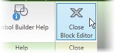
From here, I am going to close the block editor.
07:05
And this is the second most important step,
07:08
adding all of those intelligent attributes
07:10
is what makes an AutoCAD Electrical block smart.
07:15
It's also crucial to make sure that you name it appropriately
07:19
because there's a lot of intelligence
07:20
and automation built around the naming convention.
07:24
So here, I first of all want to make sure
07:26
that this block is set up to go to the right table
07:29
inside the catalog lookup.
07:31
If you remember, when we inserted
07:32
any of our other blocks, they automatically
07:35
knew which table in the catalog browser to go to.
07:39
So I want to make sure, since this is a control relay,
07:42
that it's actually going to the catalog table for control
07:47
This is very important when you're
07:48
using the generic template because
07:50
obviously generic doesn't know what that table should be.
07:54
So make sure you take a look at that catalog lookup section.
07:57
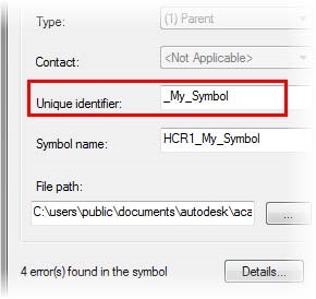
Now, the symbol naming convention
07:59
is massively important as I just stated.
08:02
These first four characters are crucial to how
08:06
that object will operate.
08:08
Let's break it down for you.
08:09
It built itself, by the way, based off of the selections
08:13
that you made in building this symbol,
08:15
which is what you don't want to just clear
08:17
this and type in whatever you want the name to be.
08:19
We need those first four to five characters.
08:23
So let's break each one of them down to explain why.
08:26
The H is either in H or a V for a horizontal
08:29
or a vertical component.
08:31
Very important for you to know how it attaches to wires,
08:34
is it horizontal or is it vertical?
08:37
This is also how it knows how to match a horizontal symbol
08:41
to a vertical symbol in those toggle options
08:44
that we have inside many of the different commands.
08:47
It can know to switch based off of that one character
08:51
The next two characters are the family code.
08:54
So in this case, a CR for a control relay.
08:57
This changes based off of the type of family of object it is.
09:01
Again, very important for it knowing what that object is.
09:06
The next character is a 1 or
09:11
also very important for how we get the right dialog
09:14
box and the right information on that symbol
09:17
to know whether or not it is a parent or a child.
09:22
There could be one more character in there
09:26
that's very crucial to understanding the toggle flips.
09:33
That is the difference between normally open and normally
09:38
If it's not an object that has a normally open or normally
09:40
closed state, then there's no character for that at all.
09:43
And we just tend to put an underscore there and then
09:46
whatever we want the unique identifier to be.
09:49
In this case, I'm going to call this my diamond relay.
09:54
And when I tab, it automatically updates the symbol name
09:57
and the png image that it's creating for my icon menu.
10:02
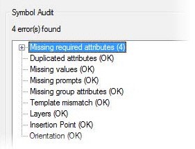
Now, it's also running an audit on my entire symbol.
10:05
So when it looks for that audit, and it's telling me
10:08
they're zero errors, it's looking for things like,
10:10
did I miss any of the required attributes?
10:13
Did I by accident copy an additional attribute, now,
10:17
Am I missing any of the values props, anything else
10:20
that I need in there?
10:21
Is there a template mismatch?
10:23
Did I say that this was a control relay
10:26
but then switched over to using all things for limit switches?
10:31
This is a very, very, very important thing
10:36
You should always create blocks on layer zero.
10:39
This is true for all things AutoCAD
10:42
through AutoCAD Electrical, but it's
10:44
crucial to AutoCAD Electrical.
10:46
You need electrical to be able to move
10:49
all of those individual pieces of those blocks
10:51
into their specific layers but electrical does so
10:55
intelligently as we place these.
10:57
They will not be able to do that if they are not on layer zero.
11:01
If you didn't know this, layer zero
11:03
is a very special layer that allows whenever
11:07
you create a block on it for the block
11:09
to then be able to take on the properties in the values
11:12
of any new layer it's inserted on.
11:15
If you've ever built a block on anything other than layer zero,
11:18
you know that every time you insert that block,
11:20
it ends up looking like the original block
11:24
that you created it on with the layer properties and everything
11:26
else that it had and it never looks like the new layer
11:30
that you're inserting it on.
11:31
That's because it wasn't built on zero.
11:33
So very, very, very important that you're on layer
11:36
zero for creating blocks.
11:38
The insertion point check here is
11:40
to make sure that your insertion point lines up with your wire
11:45
Pretty awkward, if you're trying to insert it from the top of,
11:48
say that diamond when the wire connections have
11:51
to be down at the bottom and then you end up missing it
11:53
and your wires never get trimmed.
11:55
The orientation is the final check.
11:57
And that is to make sure that you
11:59
called this a horizontal symbol but didn't put wire connection
12:02
points at the top and the bottom,
12:04
instead of putting it on the right and the left.
12:06
So those are all the checks that it will do for you.
12:08
You can run this audit on its own from here in the palate,
12:13
or you can just look for it when you're doing
12:16
the clothes out of your symbol.
12:20
Now when I come back in here, I'm
12:22
just going to make sure that my diamond relay is copied over
12:29
into this title as well.
12:34
And then you want to make sure that you
12:36
are saving your symbol and your png image where
12:41
In this case, I'm actually going to drop these onto my desktop
12:44
so that I can easily delete them.
12:46
But these should always go into your symbol libraries
12:49
and into your support files so that you can find that dwg file
12:53
and that png image to add it to your icon menu, which
12:57
we will do in the next lesson.
12:59
I'm going to click OK here.
13:01
And I am going to test this after closing the block editor.
13:04
So now I'm going to come in here,
13:05
drop it down on this wire, looking good.
13:08
It opens up my dialog box.
13:10
It trims the wires and it adds the attributes.
13:13
I know that I've successfully made an intelligent symbol now.
13:16
Please take a moment to do the exercise on custom components.