& Construction
![architecture engineering and construction collection logo](https://damassets.autodesk.net/content/dam/autodesk/www/universal-header/flyout/architecture-engineering-construction-collection-uhblack-banner-lockup-364x40.png)
Integrated BIM tools, including Revit, AutoCAD, and Civil 3D
& Manufacturing
![product design manufacturing collection logo](https://damassets.autodesk.net/content/dam/autodesk/www/universal-header/flyout/product-design-manufacturing-collection-uhblack-banner-lockup-364x40.png)
Professional CAD/CAM tools built on Inventor and AutoCAD
Integrated BIM tools, including Revit, AutoCAD, and Civil 3D
Professional CAD/CAM tools built on Inventor and AutoCAD
Transcript
00:03
UPC scripts allow you to represent the valves and pump stations within a water supply system
00:10
that may be controlled by a more complex set of rules with multiple conditions.
00:15
This UPC script example sets a valve control to perform a rezone exercise following a rupture of a pipe.
00:22
From the Model Group window, expand the UPC Model model group.
00:27
To open the UPC Network and UPC Control, double-click the UPC Network or drag and drop it onto the workspace.
00:35
In the toolbar, from the Scenario menu, select the Pipe Break scenario.
00:41
In this example, Pipe 109755 has been set to rupture between 08:00 and 12:00.
00:50
When this rupture occurs and the downstream network is left without water supply,
00:55
a mitigation method is to rezone the DMA using valve 234298.
01:01
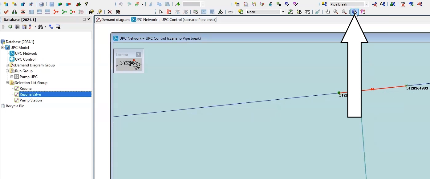
Drag and drop the Rezone Valve selection list onto the Geoplan to identify Valve 234298.
01:09
Using the Properties tool, review its current control strategy.
01:13
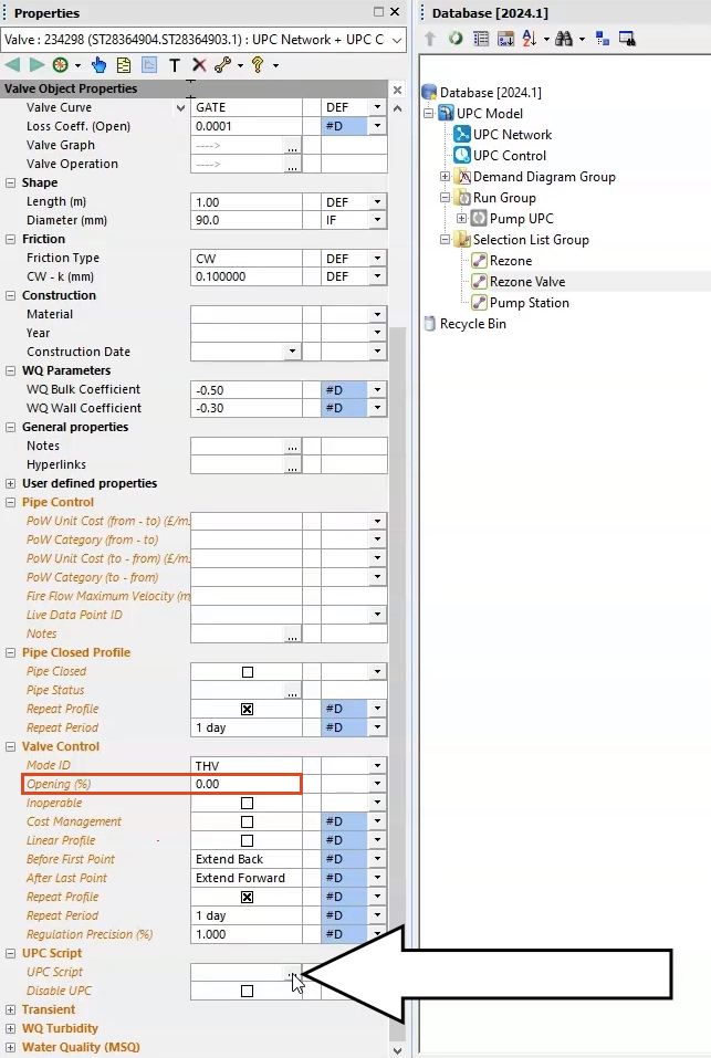
You can see from the Valve Control option that the valve is currently set to an Opening percentage of zero,
01:19
and thus the valve is closed.
01:21
You will change the behavior of this valve so that it opens when there is a supply incident in the network,
01:27
and then closes when the network behavior returns to normal.
01:31
In the Properties window of the valve, expand the UPC script menu.
01:36
In the UPC Script options, click More (…) to open the UPC Script Window.
01:42
Here, you will set the rules.
01:44
When the network is normal, the valve is closed, but when there is an incident, it opens.
01:50
From the dataset provided for this tutorial, add the lines of code provided in the Valve UPC.txt file.
01:58
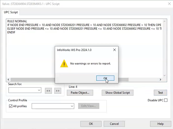
Once you have populated the code, click Test to check if there are any errors or syntax errors.
02:05
When the warning message reads, “No warnings or errors to report,” click OK to close the warning message,
02:11
and OK again to close the UPC Script window.
02:15
Commit all the changes to the database.
02:19
Now, you can run the Pipe break scenario.
02:23
Right-click the Run Group, then select New > Run.
02:28
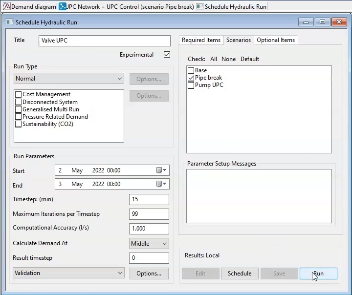
In the Schedule Hydraulic Run dialog, enter “Valve UPC” in the Title field, and check the box next to Experimental,
02:35
and then click and drag the UPC Network from the Model Group window into the Network group box.
02:41
Now, click the Scenarios tab.
02:43
Deselect the Base scenario, and then enable the Pipe Break scenario.
02:48
Then, click Save and Run.
02:52
To view the results, first click and drag the Base simulation into an empty part of the workspace window to view the results in the GeoPlan.
03:00
Now, drag and drop the Rezone selection list onto the Geoplan.
03:05
You will see the Pressure control point and the valve are selected.
03:09
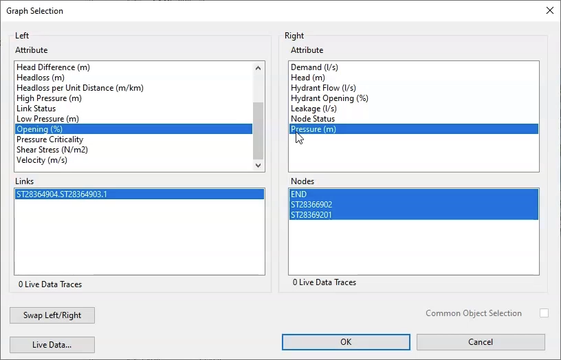
In the Results toolbar, select Graph Selected Objects.
03:14
In the Graph Selection dialog, from the Left group box, select Opening (%) and from the Right, select Pressure (m).
03:22
Click OK.
03:24
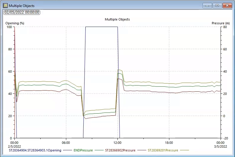
In the resulting graph, you can see that, as the pressure drops at the control points,
03:29
the rezone valve opens to allow water to bypass the rupture.
03:32
Once the pipe is mended and the flow is restored, the rezone valve closes.
Video transcript
00:03
UPC scripts allow you to represent the valves and pump stations within a water supply system
00:10
that may be controlled by a more complex set of rules with multiple conditions.
00:15
This UPC script example sets a valve control to perform a rezone exercise following a rupture of a pipe.
00:22
From the Model Group window, expand the UPC Model model group.
00:27
To open the UPC Network and UPC Control, double-click the UPC Network or drag and drop it onto the workspace.
00:35
In the toolbar, from the Scenario menu, select the Pipe Break scenario.
00:41
In this example, Pipe 109755 has been set to rupture between 08:00 and 12:00.
00:50
When this rupture occurs and the downstream network is left without water supply,
00:55
a mitigation method is to rezone the DMA using valve 234298.
01:01
Drag and drop the Rezone Valve selection list onto the Geoplan to identify Valve 234298.
01:09
Using the Properties tool, review its current control strategy.
01:13
You can see from the Valve Control option that the valve is currently set to an Opening percentage of zero,
01:19
and thus the valve is closed.
01:21
You will change the behavior of this valve so that it opens when there is a supply incident in the network,
01:27
and then closes when the network behavior returns to normal.
01:31
In the Properties window of the valve, expand the UPC script menu.
01:36
In the UPC Script options, click More (…) to open the UPC Script Window.
01:42
Here, you will set the rules.
01:44
When the network is normal, the valve is closed, but when there is an incident, it opens.
01:50
From the dataset provided for this tutorial, add the lines of code provided in the Valve UPC.txt file.
01:58
Once you have populated the code, click Test to check if there are any errors or syntax errors.
02:05
When the warning message reads, “No warnings or errors to report,” click OK to close the warning message,
02:11
and OK again to close the UPC Script window.
02:15
Commit all the changes to the database.
02:19
Now, you can run the Pipe break scenario.
02:23
Right-click the Run Group, then select New > Run.
02:28
In the Schedule Hydraulic Run dialog, enter “Valve UPC” in the Title field, and check the box next to Experimental,
02:35
and then click and drag the UPC Network from the Model Group window into the Network group box.
02:41
Now, click the Scenarios tab.
02:43
Deselect the Base scenario, and then enable the Pipe Break scenario.
02:48
Then, click Save and Run.
02:52
To view the results, first click and drag the Base simulation into an empty part of the workspace window to view the results in the GeoPlan.
03:00
Now, drag and drop the Rezone selection list onto the Geoplan.
03:05
You will see the Pressure control point and the valve are selected.
03:09
In the Results toolbar, select Graph Selected Objects.
03:14
In the Graph Selection dialog, from the Left group box, select Opening (%) and from the Right, select Pressure (m).
03:22
Click OK.
03:24
In the resulting graph, you can see that, as the pressure drops at the control points,
03:29
the rezone valve opens to allow water to bypass the rupture.
03:32
Once the pipe is mended and the flow is restored, the rezone valve closes.
UPC scripts allow you to represent the valves and pump stations within a water supply system that may be controlled by a more complex set of rules with multiple conditions. In this example, a UPC script sets a valve control to perform a rezone exercise following a pipe rupture.
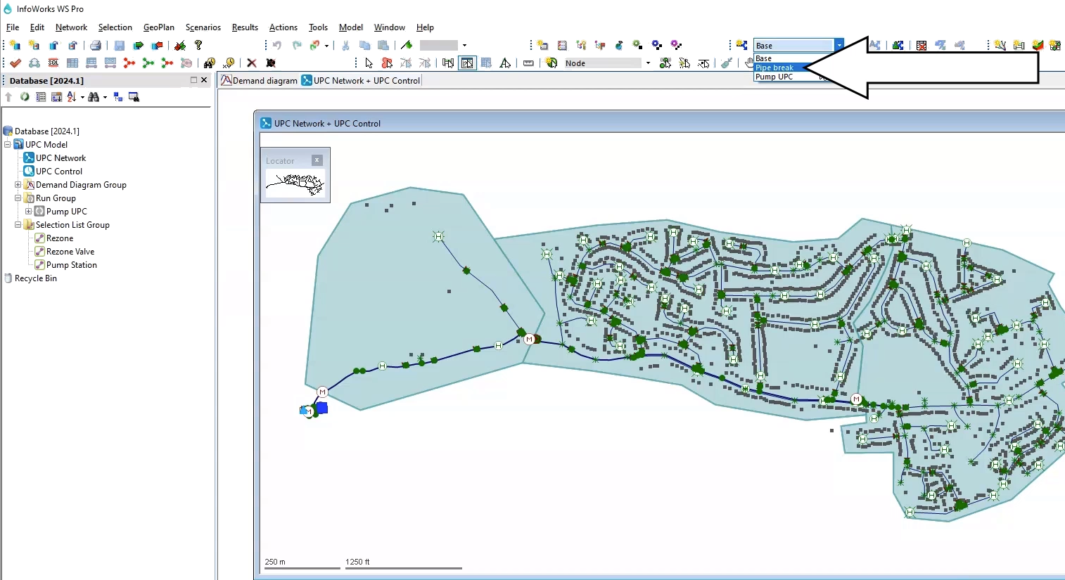
For this example, Pipe 109755 has been set to rupture between 08:00 and 12:00. When this rupture occurs and leaves the downstream network without water supply, the mitigation method is to rezone the DMA using valve 234298.
The Valve Control option is currently set to an Opening percentage of zero, meaning the valve is closed.
Now, create a UPC script that instructs the valve to open when there is a supply incident in the network, and then close when the network behavior returns to normal.
To run the Pipe break scenario:
Now, graph the results:
In the resulting graph, you can see that as the pressure drops at the control points, the rezone valve opens to allow water to bypass the rupture. Once the pipe is mended and the flow is restored, the rezone valve closes.
How to buy
Privacy | Do not sell or share my personal information | Cookie preferences | Report noncompliance | Terms of use | Legal | © 2025 Autodesk Inc. All rights reserved
Sign in to start learning
Sign in for unlimited free access to all learning content.Save your progress
Take assessments
Receive personalized recommendations
May we collect and use your data?
Learn more about the Third Party Services we use and our Privacy Statement.May we collect and use your data to tailor your experience?
Explore the benefits of a customized experience by managing your privacy settings for this site or visit our Privacy Statement to learn more about your options.