Step-by-step guide
RTC can be defined for one or more regulators—control elements that can physically regulate flow, depth, or velocity values in the network. This example uses RTC to store flow in an upstream tank to reduce the spill from the downstream storm tank, and to control the release of flow from the tank.
To complete this exercise, open the transportable database .icmt file for this tutorial.
- In the Model Group, open the 1D Simulation Model by double-clicking the network or by dragging it onto the GeoPlan.
Create a new scenario to apply the RTC:
- In the Scenarios toolbar, click Create scenario.
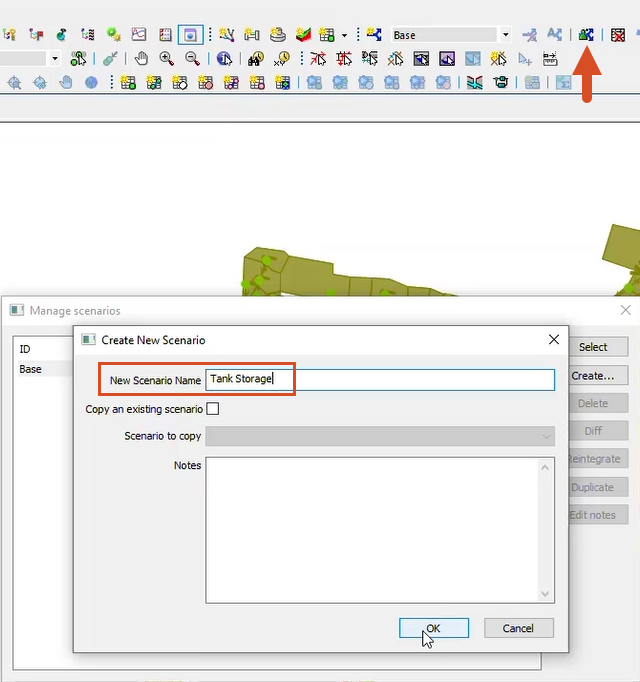
- OR, as shown in the image, click Manage scenarios, and then click Create.
- In the Create New Scenario dialog box, enter the name "Tank Storage", and then click OK.
- Click the Find in GeoPlan tool.
- Perform a Quick Find for Storm_Tank1.1.
- Close the Quick Find dialog box.
- Double-click the upstream node to open its properties.
RTC can only be applied to certain link types, or more specifically, to links with variable properties.
- Next to Link type, use the drop-down to change the type to VSGate, which is a variable vertical sluice.
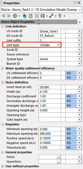
Once the change is made, regulator properties are added to the Properties dialog box.
- While still in the Tank Storage scenario, click the Grid windows drop-down and select RTC editor.
- In the RTC Window Editor, right-click Global and select Insert regulator.
The Select regulator popup appears, displaying all the regulator links in the model that can be controlled via RTC.
- Select Storm_Tank1.1.
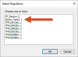
- Click OK.
The regulator is added to the RTC tree structure, and the rules can now be defined for it to follow.
In this example, the sluice gate is to remain shut, unless the level within the inlet channel is less than 41.00m AD.
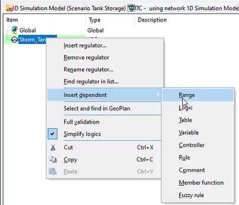
- Right-click Storm_Tank1.1 and select Insert dependent > Range.
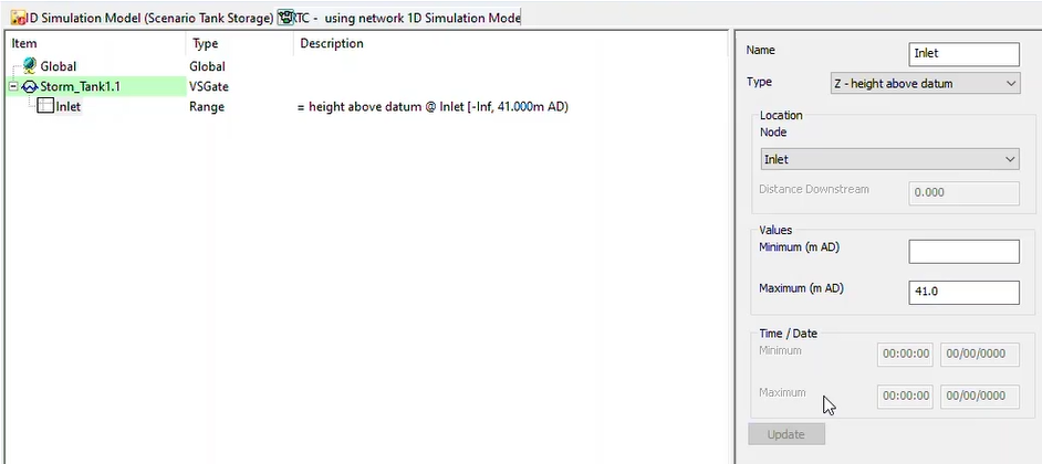
- Expand the Storm_Tank1.1 entry and select NewRange to display its settings in the right-hand pane.
- Set the Name as “Inlet”.
- Set the Type to Z - height above datum.
- Set the Location to Inlet.
- Set the Maximum (m AD) to 41.000.
- Click Update to save the information.
Now define the rules.
The variable for the VSGate is the opening height.
- Right-click Storm_Tank1.1 and select Insert dependent > Rule.
- Set the Condition to _Default_.
- Set the Type to POS.
- Ensure that the Setpoint Type is Fixed at 0.000 m.
- Click Update to save the information.
Next, define a second rule for when the sluice should open:
- Right-click Storm_Tank1.1 and select Insert dependent > Rule.
- Set the Condition to Inlet, which looks at the Range set earlier.
- Set the Type to POS.
- Under Setpoint Type, select Fixed.
- Enter a value of 0.150 m.
- Click Update.
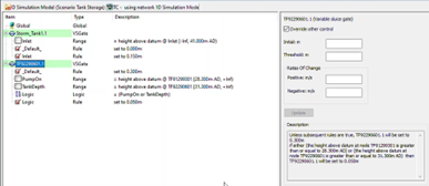
- Select the regulator Storm_Tank1.1.
- In the Description box, notice the description of the rules in plain English. This is useful to read and determine whether the RTC is logical.
Now, define the rules for the upstream storage tank. The tank should contain flow when the downstream pumping station is on, and hold back the water until the online tank has drained.
- Leave the RTC Window Editor open and switch back to the model on the GeoPlan.
- Click Find in GeoPlan.
- Perform a Quick Find for link TF92290601.1.
- Close the Quick Find dialog box.
To change link TF92290601.1 from a conduit to a regulator link, it needs to be deleted and then recreated.
- With only the link is selected, in the Selection toolbar, click Delete selection.
- Expand the New Object drop-down and select Link.
- Click the New object tool.
- Draw a link from TF92290601 to TF91299602.
- In the Create New Link dialog box, set the Type to Sluice.
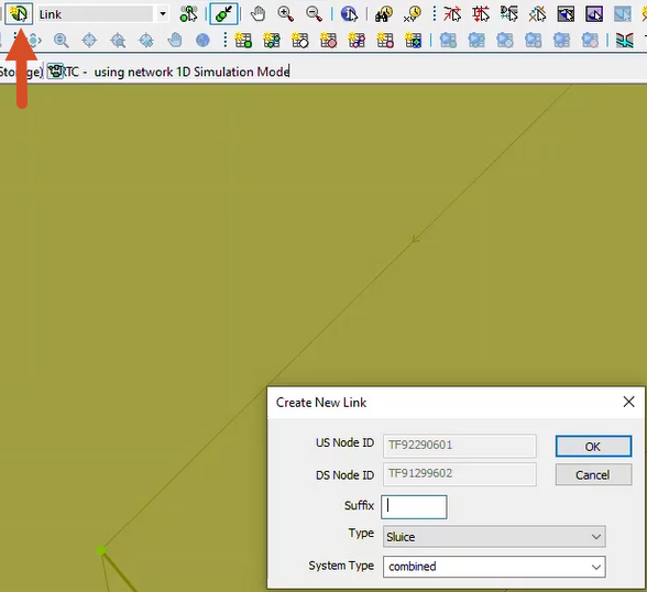
- Click OK.
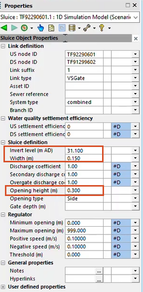
- In the Properties dialog box for the new sluice, set the Link type to VSGate.
- Under Sluice definition, set the Invert Level (m AD) to 31.100.
- Set the Width (m) to 0.150.
- Set the Opening height (m) to 0.300.
- Switch back to the RTC Window Editor.
- Right-click Global and select Insert regulator.
- In the Select Regulators dialog box, select TF92290601.1.
- Click OK.
Set up the rules for this regulator:
- Right-click TF92290601.1 and select Insert dependent > Rule.
- Expand the TF92290601.1 entry.
- Select the NewRange item to display its settings.
- Set the Condition to _Default_.
- Set the Type to POS.
- Set the Setpoint Type to Fixed at 0.3 m.
- Click Update.
- Right-click TF92290601.1 and select Insert dependent > Range.
- Set the Name to "PumpOn".
- Set the Type to Z - height above datum.
- Set the Node to TF91299301.
- Set the Values Minimum (m AD) to 28.300.
- Click Update.
- Set up a second Range with the Name "Tank Depth".
- Set the Type to Z - height above datum.
- Set the Node to TF92290601.
- Set the Values Minimum (m AD) to 31.300.
- Click Update.
The sluice should remain at a 50mm opening height during both of the range conditions. Use a logic table to set this up:
- Right-click TF92290601.1 and select Insert dependent > Logic.
- Set the Name to "Logic".
- Set the Operator to OR.
- In the Dependent Conditions drop-downs, select the two ranges that were previously defined, PumpOn and TankDepth.
- Click Update.
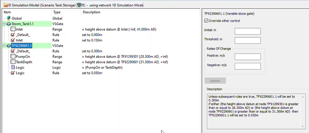
Finally, create a new rule that looks at the logic just created as its condition and sets the opening height of the sluice.
- Right-click TF92290601.1 and select Insert dependent > Rule.
- Set the Condition to Logic.
- Set the Type to POS.
- Set the Setpoint Type to Fixed at 0.050 m.
- Click Update.
The RTC is now finalized.
- Click regulator TF92290601.1 and read through the Description to make sure everything looks logical.
- Close the RTC Window Editor.
To use this RTC in a simulation, first, these latest changes need to be validated and committed.
- Click Validate.
- In the Network Validation popup, select the Tank Storage Scenario.
- Click OK.
- Ensure that there are no errors in the Output Window, and then click Commit changes.
- In the popup, add the comment "RTC added at two sluices".
- Click OK.
The impact that the addition of the sluice and RTC have on the model and the spills from the storm tank are ready to be tested.


