Step-by-step guide
To run the automatic calibration module, an appropriate live data configuration must be set up for the model.
To create a new Live Data Configuration object:
- In the Model Group, expand Calibration Model.
- Right-click the Calibration model group and select New > Live Data Configuration.
- Double-click the Live Data Configuration object to open it.
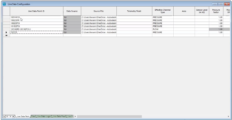
- In the Live Data Configuration dialog box, click the Live Data Points tab.
- Open a local file browser to access the dataset for this tutorial.
- Navigate to the Calibration Live Data folder and select all the text (.txt) files.

- Ensure the Live Data Point tab is active.
- Drag and drop the text files into the first cell.
The live data files automatically load into the table:
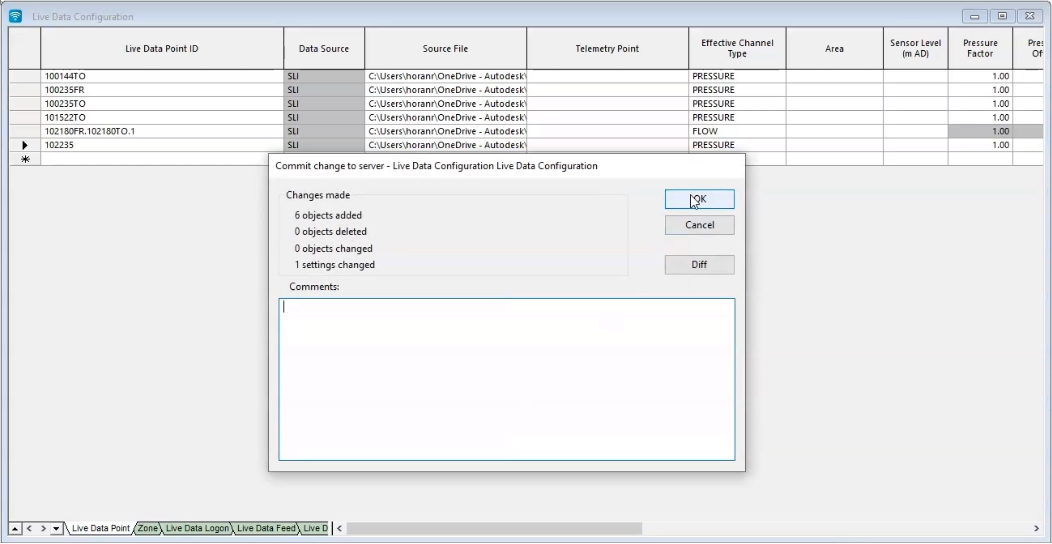
To commit the changes to the Live data configuration to the database:
- In the Model Group, right-click Live Data Configuration and select Commit changes to database.
- In the Warning dialog box, click Yes.
- In the Commit change to server – Live Data Configuration dialog box, click OK.
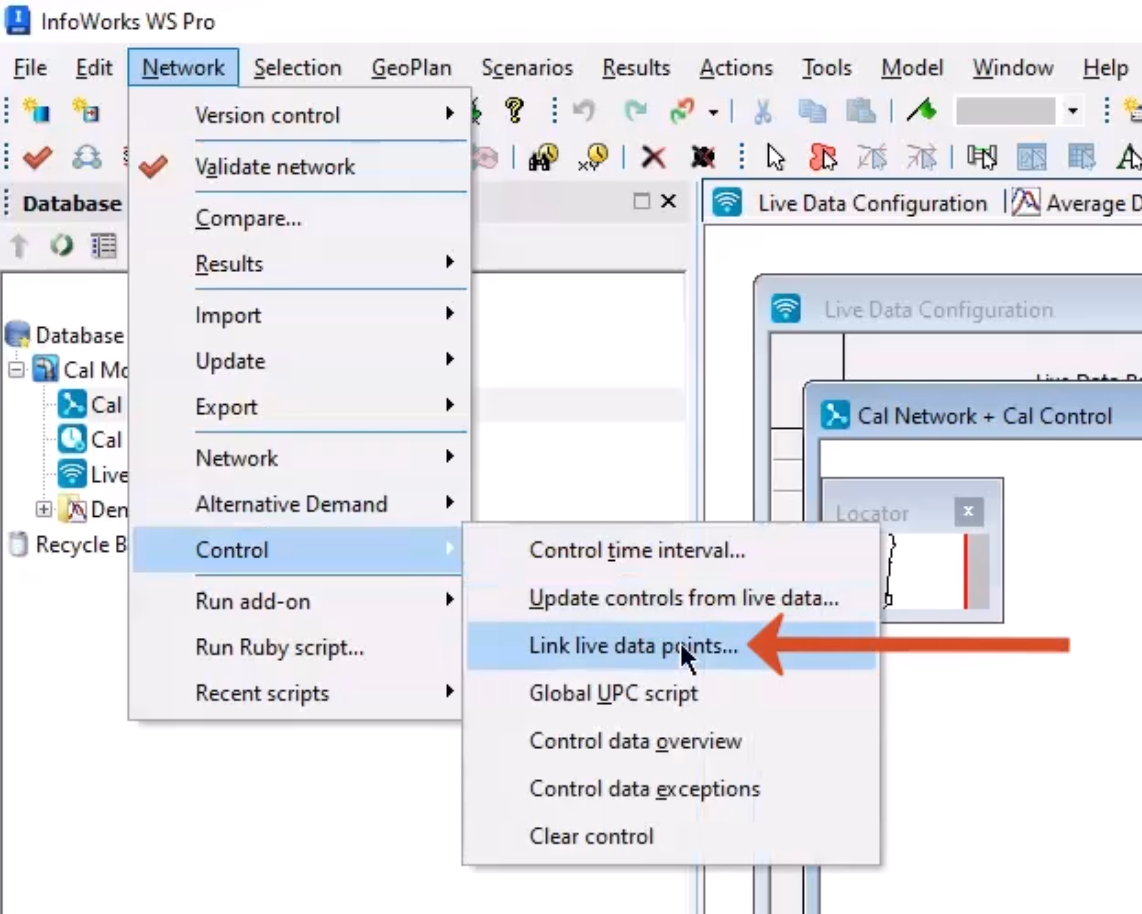
Before the live data can be used with the model, it needs to be associated with the network. This association is done using the control file in InfoWorks WS Pro.
Each logger data file is referenced in the Live Data Configuration using a Live Data Point ID. This field provides the link between the logger data and the model.
To associate the live data with the network:
- Ensure that the Live Data Configuration is open behind the BridgeTown Network and BridgeTown Control.
- In the Network menu, select Control > Link live data points to open the Link Live Data Points dialog box.
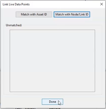
- Click the Match with Asset ID button.
- Click the Match with Node/Link ID button.
In this example, nothing is listed in the Unmatched: group box, which means that everything is correctly matched.
- Click Done.
To select and highlight all the objects with live data attached:
- Right-click the GeoPlan and click Selection > Select live data point objects.

- In the toolbar, click Clear selection.
- Commit any outstanding changes to the network and control to the database.


