& Construction

Integrated BIM tools, including Revit, AutoCAD, and Civil 3D
& Manufacturing

Professional CAD/CAM tools built on Inventor and AutoCAD

Integrated BIM tools, including Revit, AutoCAD, and Civil 3D

Professional CAD/CAM tools built on Inventor and AutoCAD
Create bank lines and build a bank connection using linear coupling.
Type:
Tutorial
Length:
10 min.
Tutorial resources
These downloadable resources will be used to complete this tutorial:
Transcript
00:04
In ICM, coupling at bank lines connects 1D model objects to multiple 2D element faces.
00:11
This can occur at either river reach banks or inline bank links,
00:16
both of which are built from bank line data.
00:19
In this tutorial, you create bank lines for river reach objects and build a bank connection.
00:26
To begin, from the File menu, select Open > Open transportable database.
00:33
Navigate to the folder where you downloaded the exercise files for this tutorial,
00:39
select the .icmt file, and then click Open.
00:44
If you see a popup about opening the database as read-only, click Yes.
00:50
In the transportable database window, right-click the top-level folder, and select Copy.
00:57
In the popup, click Continue.
01:00
Right-click the Database and select Paste (with children).
01:05
In the Copying pop-up, enable Copy ground models.
01:10
Click Continue.
01:12
In the Explorer window, double-click 1D/2D River Model to open it on the GeoPlan.
01:21
From the Database, drag 1m Ground Model and drop it onto the GeoPlan.
01:28
You can now import a 2D zone.
01:31
From the Network menu, click Import, then select Open Data Import Centre to open the ODIC.
01:40
In the Table To Import Data Into drop-down, select 2D zone.
01:46
Under Data Source, ensure the Source Type is set to Raw Shape File.
01:53
Click the More (…) button, navigate to the exercise files for this tutorial,
01:59
select 2D Zone.shp, and then click Open.
02:05
In the Field Mapping Configuration section,
02:08
click Auto-Map to search the import file for fields that match those defined in the network.
02:15
Click Import.
02:17
An import notification lets you know how many objects were imported.
02:22
Click OK, and then Close the ODIC.
02:26
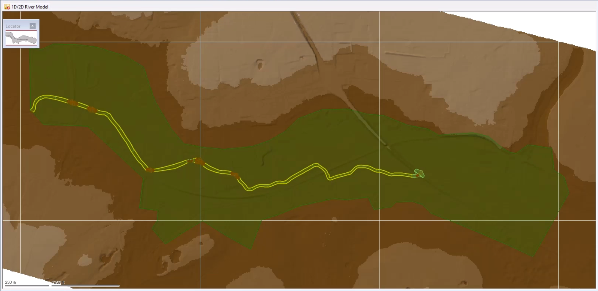
The 2D zone is imported into the model and is displayed as a green polygon.
02:33
Click the Select tool, and then double-click the 2D zone to open its Properties window.
02:40
Set the following mesh parameters:
02:43
Set the Maximum triangle area to 200
02:47
Set the Minimum element area to 20
02:51
Set the Mesh generation to Classic
02:55
Enable Terrain-sensitive meshing
02:58
Set the Maximum height variation to 0.2
03:03
Set the Roughness (Manning's n) to 0.04
03:09
With these changes made, you can generate the mesh.
03:13
Make sure the 2D Zone is still selected on the GeoPlan.
03:18
From the Model menu, select Meshing > Mesh 2D zones.
03:23
From the Database, drag the 1m Ground Model into the Mesh 2D Zones dialog
03:30
and drop it into the Ground Model group box.
03:34
Click OK to mesh the 2D zone.
03:38
In the Schedule Job(s) dialog, click OK.
03:43
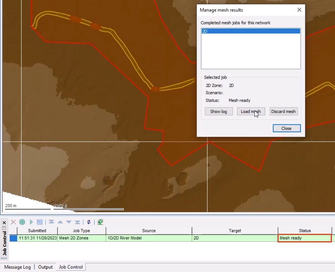
From the Window menu, select Job control window to display the status of the mesh job.
03:50
Once the mesh is complete, it can be loaded into the model.
03:54
From the Job control window, click the Mesh ready status
03:58
to open the Manage mesh results window.
04:02
Click Load mesh, and then Close.
04:06
Inspect the 2D mesh to see how the terrain sensitive meshing has affected the element sizes in different areas of the model.
04:14
It may be helpful to adjust the Ground Model theme to see the mesh better.
04:20
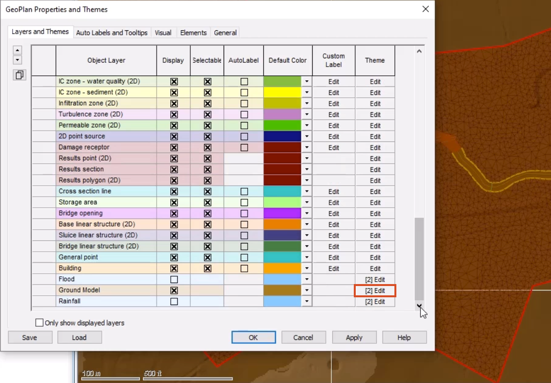
Right-click the GeoPlan and select Properties & themes.
04:25
On the Layers and Themes tab, for the Ground Model object layer, in the Theme column, click Edit.
04:33
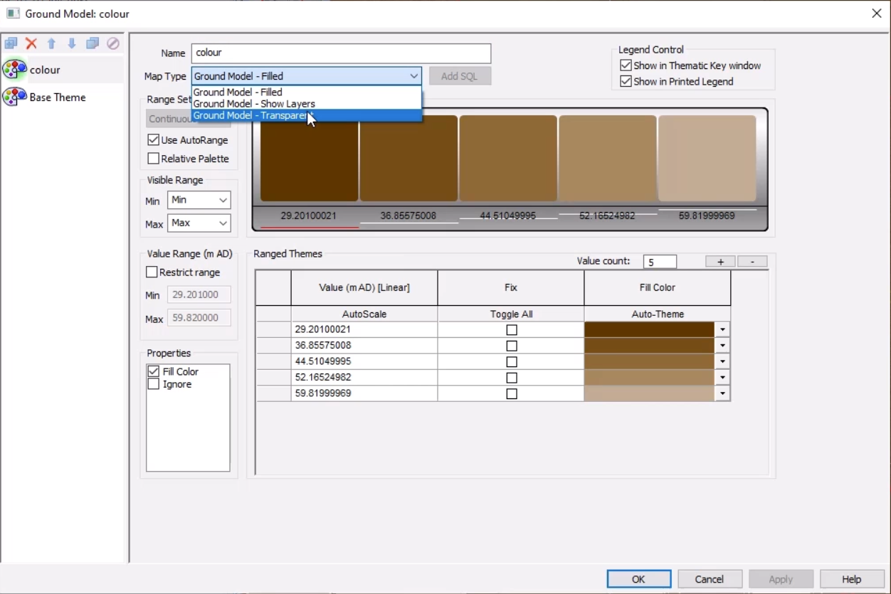
In the Map Type drop-down, select Ground Model – Transparent.
04:38
Click OK, then OK again to close the GeoPlan Properties and Themes window.
04:45
Notice that the 2D zone extends beyond the river model.
04:50
This is because this downstream area is complex and best represented in 2D.
04:56
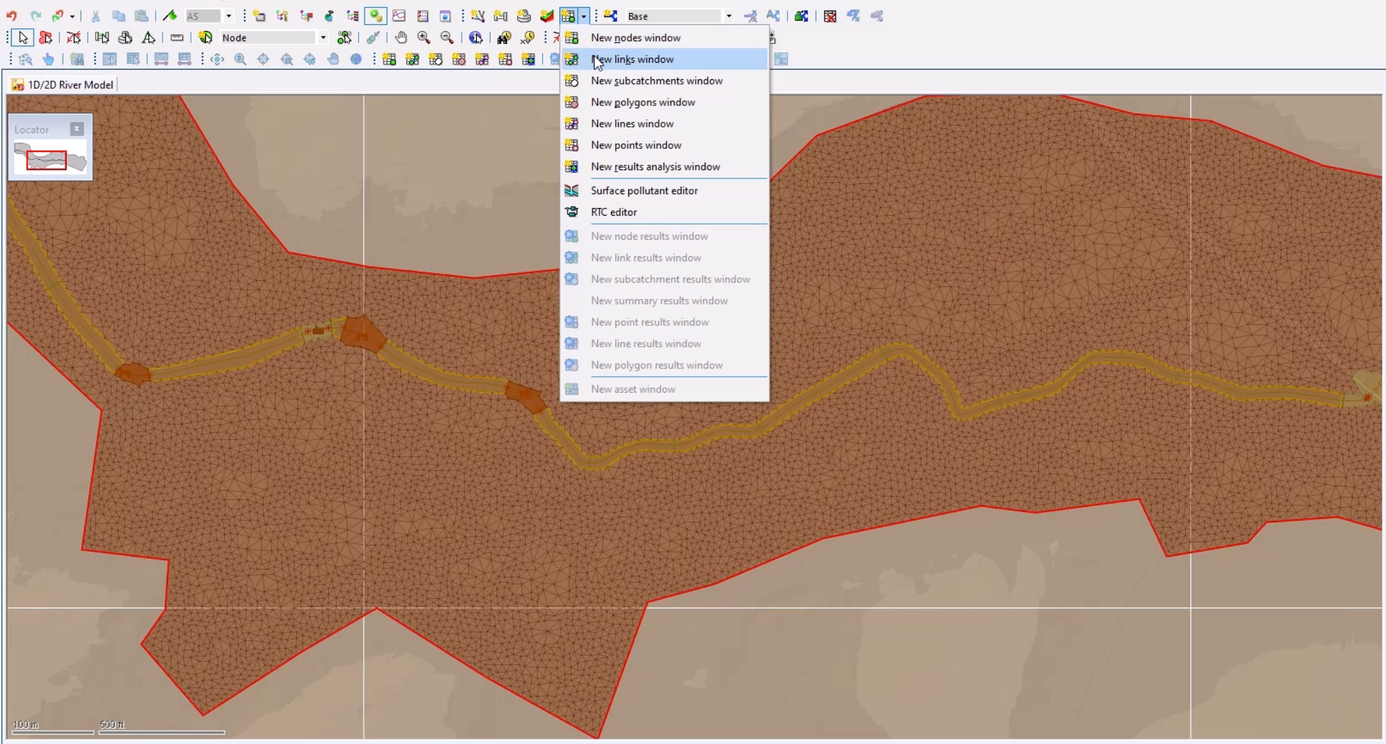
From the Windows toolbar, expand the Grid windows drop-down and select New links window.
05:04
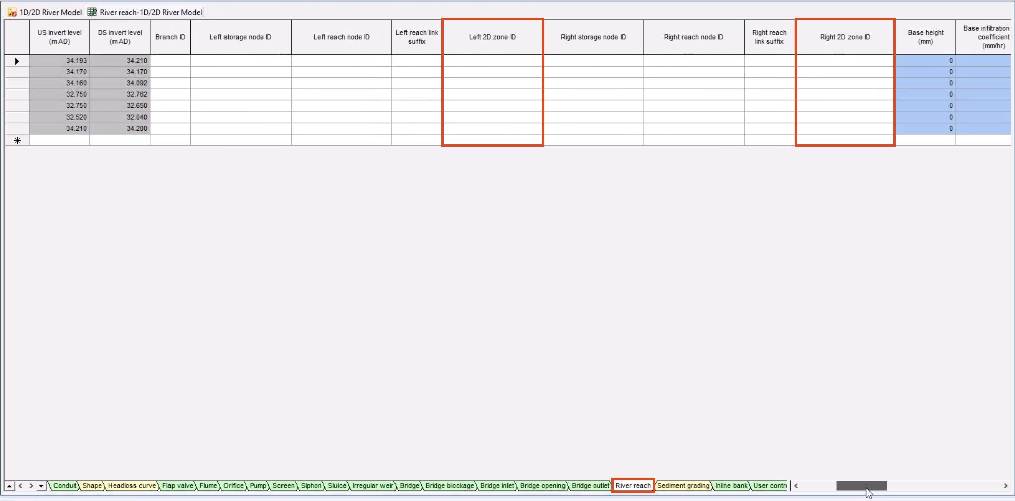
At the bottom of the grid window, select the River reach tab to view data for the seven river reaches.
05:11
Note that the Left 2D zone ID and Right 2D zone ID columns are blank.
05:19
Currently, if you ran a simulation on the model, there would be no exchange of flow.
05:25
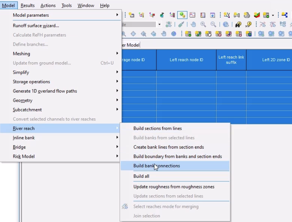
To connect the bank lines to the 2D zone, click the top left of the grid to select all the river reaches.
05:33
From the Model menu, select River reach > Build bank connections.
05:39
The Left 2D zone ID and Right 2D zone ID columns now display “2D”, the name of the 2D zone you imported earlier.
05:50
Close the grid window.
05:52
To help visualize the bank lines in the model, right-click the model on the GeoPlan and select Properties & themes.
06:01
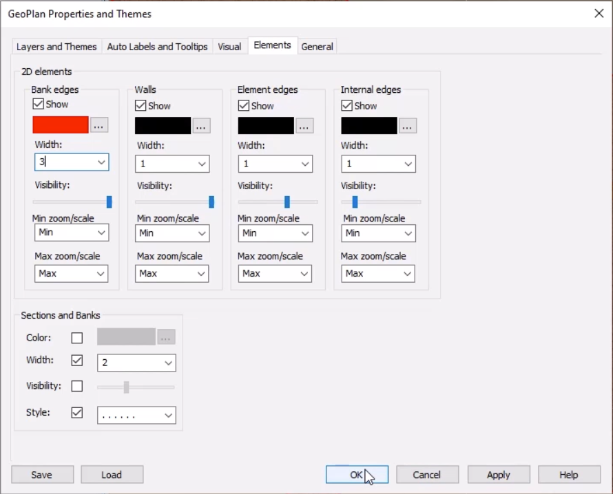
On the Elements tab, in the 2D elements section for Bank edges,
06:07
click More (…) to change the color to red, and then set the Width to 3.
06:15
Click OK.
06:17
At this point there are no bank connections, as you need to regenerate the mesh.
06:23
With the 2D zone selected on the GeoPlan, select Model > Meshing > Mesh 2D zones, and then click OK.
06:33
In the Schedule Job(s) dialog, click OK.
06:38
Once the mesh is complete, from the Job control window,
06:43
click the Mesh ready status to open the Manage mesh results window.
06:48
As you click Load mesh, note that the bank lines are correctly connected to the 2D zone,
06:55
highlighted by the red bank edges.
06:58
Select Close.
07:00
Click Validate to make sure there are no errors in your network, and then click OK.
07:07
Click Commit changes to database to save your changes.
07:12
Add a comment, such as "Added 2D zone and connected the banks".
07:20
Click OK.
07:21
You now have a 1D-2D river network that is coupled along the banks.
Video transcript
00:04
In ICM, coupling at bank lines connects 1D model objects to multiple 2D element faces.
00:11
This can occur at either river reach banks or inline bank links,
00:16
both of which are built from bank line data.
00:19
In this tutorial, you create bank lines for river reach objects and build a bank connection.
00:26
To begin, from the File menu, select Open > Open transportable database.
00:33
Navigate to the folder where you downloaded the exercise files for this tutorial,
00:39
select the .icmt file, and then click Open.
00:44
If you see a popup about opening the database as read-only, click Yes.
00:50
In the transportable database window, right-click the top-level folder, and select Copy.
00:57
In the popup, click Continue.
01:00
Right-click the Database and select Paste (with children).
01:05
In the Copying pop-up, enable Copy ground models.
01:10
Click Continue.
01:12
In the Explorer window, double-click 1D/2D River Model to open it on the GeoPlan.
01:21
From the Database, drag 1m Ground Model and drop it onto the GeoPlan.
01:28
You can now import a 2D zone.
01:31
From the Network menu, click Import, then select Open Data Import Centre to open the ODIC.
01:40
In the Table To Import Data Into drop-down, select 2D zone.
01:46
Under Data Source, ensure the Source Type is set to Raw Shape File.
01:53
Click the More (…) button, navigate to the exercise files for this tutorial,
01:59
select 2D Zone.shp, and then click Open.
02:05
In the Field Mapping Configuration section,
02:08
click Auto-Map to search the import file for fields that match those defined in the network.
02:15
Click Import.
02:17
An import notification lets you know how many objects were imported.
02:22
Click OK, and then Close the ODIC.
02:26
The 2D zone is imported into the model and is displayed as a green polygon.
02:33
Click the Select tool, and then double-click the 2D zone to open its Properties window.
02:40
Set the following mesh parameters:
02:43
Set the Maximum triangle area to 200
02:47
Set the Minimum element area to 20
02:51
Set the Mesh generation to Classic
02:55
Enable Terrain-sensitive meshing
02:58
Set the Maximum height variation to 0.2
03:03
Set the Roughness (Manning's n) to 0.04
03:09
With these changes made, you can generate the mesh.
03:13
Make sure the 2D Zone is still selected on the GeoPlan.
03:18
From the Model menu, select Meshing > Mesh 2D zones.
03:23
From the Database, drag the 1m Ground Model into the Mesh 2D Zones dialog
03:30
and drop it into the Ground Model group box.
03:34
Click OK to mesh the 2D zone.
03:38
In the Schedule Job(s) dialog, click OK.
03:43
From the Window menu, select Job control window to display the status of the mesh job.
03:50
Once the mesh is complete, it can be loaded into the model.
03:54
From the Job control window, click the Mesh ready status
03:58
to open the Manage mesh results window.
04:02
Click Load mesh, and then Close.
04:06
Inspect the 2D mesh to see how the terrain sensitive meshing has affected the element sizes in different areas of the model.
04:14
It may be helpful to adjust the Ground Model theme to see the mesh better.
04:20
Right-click the GeoPlan and select Properties & themes.
04:25
On the Layers and Themes tab, for the Ground Model object layer, in the Theme column, click Edit.
04:33
In the Map Type drop-down, select Ground Model – Transparent.
04:38
Click OK, then OK again to close the GeoPlan Properties and Themes window.
04:45
Notice that the 2D zone extends beyond the river model.
04:50
This is because this downstream area is complex and best represented in 2D.
04:56
From the Windows toolbar, expand the Grid windows drop-down and select New links window.
05:04
At the bottom of the grid window, select the River reach tab to view data for the seven river reaches.
05:11
Note that the Left 2D zone ID and Right 2D zone ID columns are blank.
05:19
Currently, if you ran a simulation on the model, there would be no exchange of flow.
05:25
To connect the bank lines to the 2D zone, click the top left of the grid to select all the river reaches.
05:33
From the Model menu, select River reach > Build bank connections.
05:39
The Left 2D zone ID and Right 2D zone ID columns now display “2D”, the name of the 2D zone you imported earlier.
05:50
Close the grid window.
05:52
To help visualize the bank lines in the model, right-click the model on the GeoPlan and select Properties & themes.
06:01
On the Elements tab, in the 2D elements section for Bank edges,
06:07
click More (…) to change the color to red, and then set the Width to 3.
06:15
Click OK.
06:17
At this point there are no bank connections, as you need to regenerate the mesh.
06:23
With the 2D zone selected on the GeoPlan, select Model > Meshing > Mesh 2D zones, and then click OK.
06:33
In the Schedule Job(s) dialog, click OK.
06:38
Once the mesh is complete, from the Job control window,
06:43
click the Mesh ready status to open the Manage mesh results window.
06:48
As you click Load mesh, note that the bank lines are correctly connected to the 2D zone,
06:55
highlighted by the red bank edges.
06:58
Select Close.
07:00
Click Validate to make sure there are no errors in your network, and then click OK.
07:07
Click Commit changes to database to save your changes.
07:12
Add a comment, such as "Added 2D zone and connected the banks".
07:20
Click OK.
07:21
You now have a 1D-2D river network that is coupled along the banks.
In ICM, coupling at bank lines connects 1D model objects to multiple 2D element faces. This can occur at either river reach banks or inline bank links, both of which are built from bank line data.
This example creates bank lines for river reach objects and builds a bank connection.
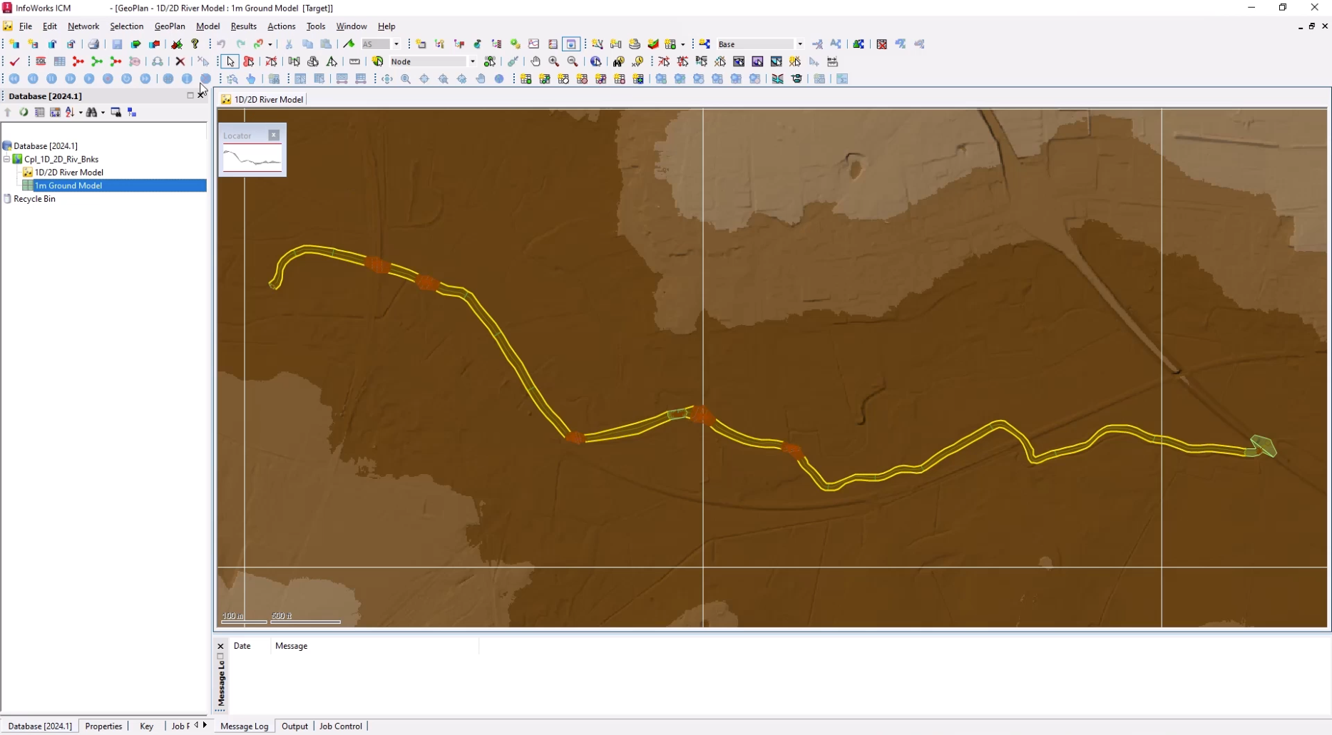
Now, import a 2D zone:
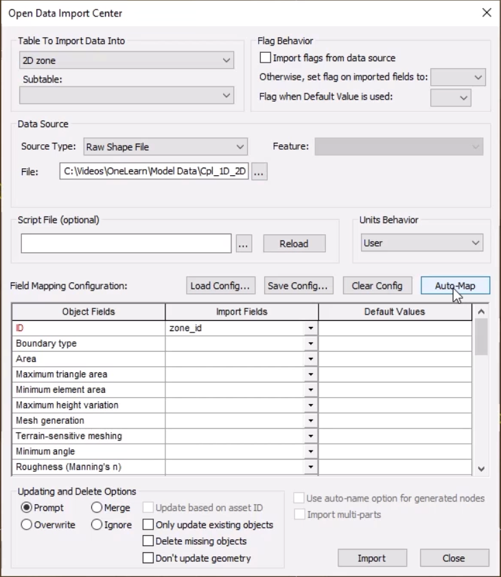
An import notification reports the number of imported objects.
The 2D zone is imported into the model and is displayed as a green polygon.
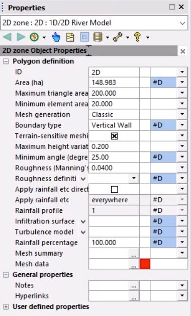
With these changes made, the mesh can be generated:
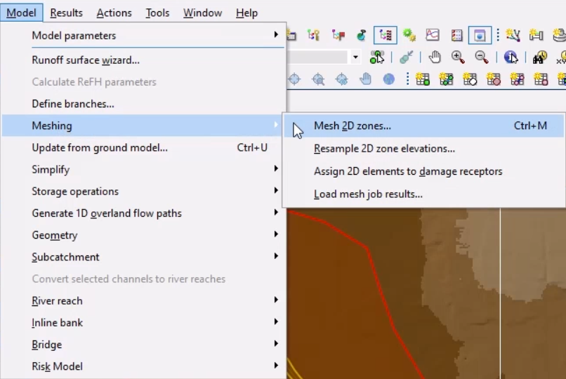
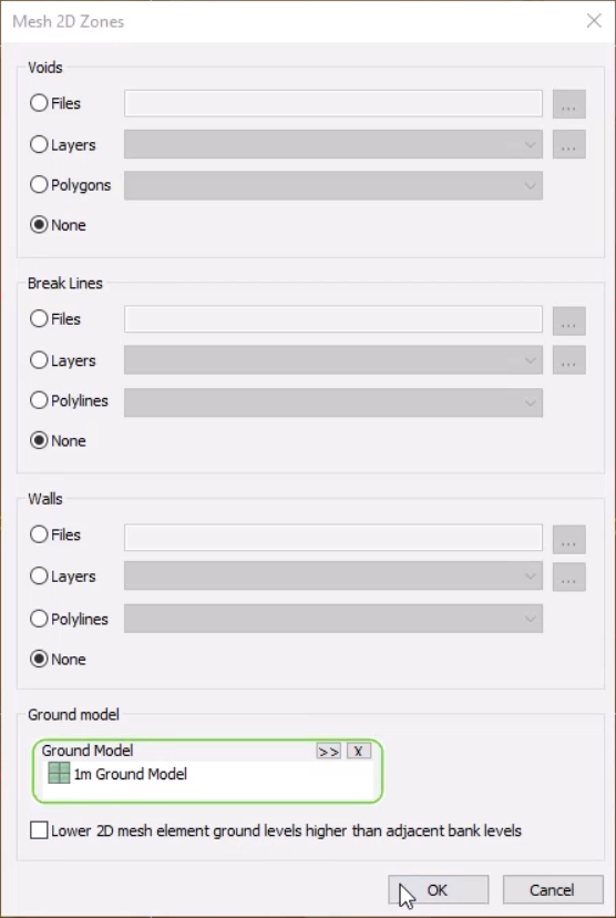
Once the mesh is complete, it can be loaded into the model.
It may be helpful to adjust the Ground Model theme to see the mesh better.
Notice that the 2D zone extends beyond the river model. This is because this downstream area is complex and best represented in 2D.
Note that the Left 2D zone ID and Right 2D zone ID columns are blank. Currently, if a simulation were run on the model, there would be no exchange of flow.
To connect the bank lines to the 2D zone:
The Left 2D zone ID and Right 2D zone ID columns now display “2D”, the name of the 2D zone imported earlier.

To help visualize the bank lines in the model:
At this point, there are no bank connections, as the mesh needs to be regenerated.
Note that the bank lines are correctly connected to the 2D zone, highlighted by the red bank edges.
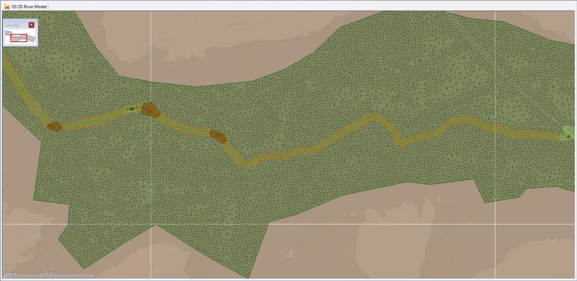
The 1D-2D river network is now coupled along the banks.
How to buy
Privacy | Do not sell or share my personal information | Cookie preferences | Report noncompliance | Terms of use | Legal | © 2025 Autodesk Inc. All rights reserved
Sign in for the best experience
Save your progress
Get access to courses
Receive personalized recommendations
May we collect and use your data?
Learn more about the Third Party Services we use and our Privacy Statement.May we collect and use your data to tailor your experience?
Explore the benefits of a customized experience by managing your privacy settings for this site or visit our Privacy Statement to learn more about your options.