Step-by-step guide
Revit provides electrical engineering load estimating workflows that allow decision-making early in the design process. Capturing the area-based loads and other electrical requirements natively within Revit allows users to determine what the preliminary building load will be.
To define the electrical analytical loads:
- Open the plan on which to base the electrical analysis.
- Open the System Browser.
Area-based loads can be created using a variety of reference data, such as an architectural RVT, DWG, or PDF.
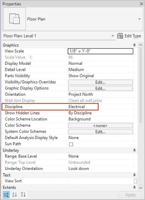
- In the Properties palette, set the Discipline to Electrical.
Before electrical area-based loads can be defined, a closed region must first be defined using area-based load boundaries.
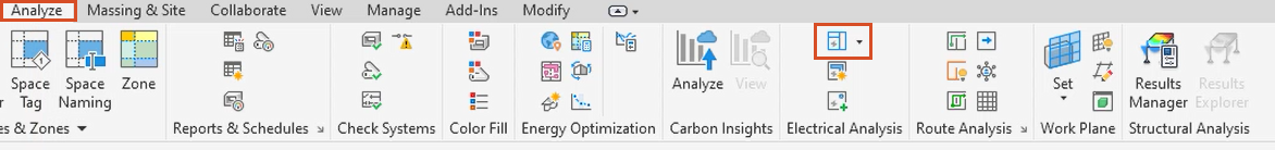
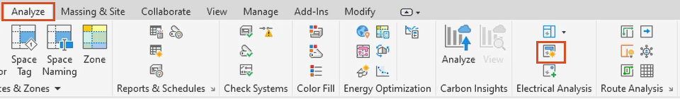
- From the Analyze tab, Electrical Analysis panel, select Area Based Load Boundary.
On the Modify | Place Area Based Load Boundary contextual tab, either use the Draw tools to sketch the area-based load boundary, or use the existing walls, lines, or edges to define the boundary.
To use existing lines:
- From the Draw panel, select Pick Line.
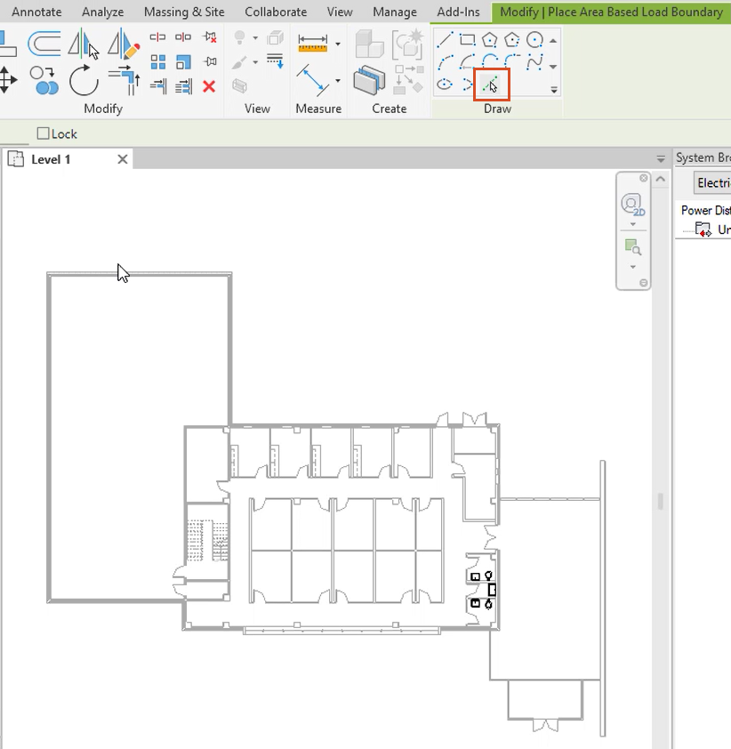
- In the drawing area, pick the lines of the boundary.
In this example, the plan includes curtain walls, which need to be cleaned up:
- After picking the remainder of the building perimeter, on the ribbon, Modify tab, Modify panel, select Trim/Extend to Corner.
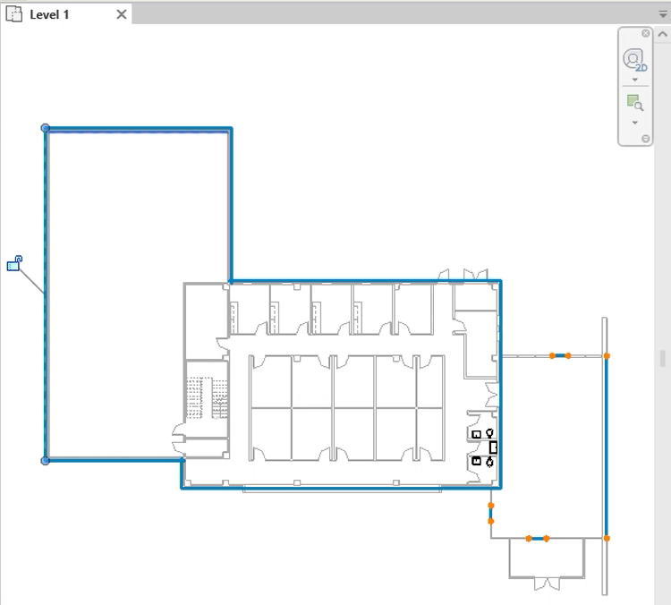
- In the drawing, select two unconnected elements to connect them, repeating this process until the perimeter of the border is continuous and includes the curtain wall.
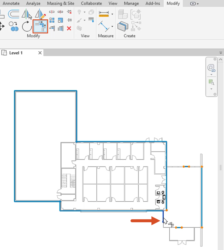
- Click Modify to complete the boundary.
With the area-based load boundary in place, define the electrical area-based loads within it:
- On the ribbon, Analyze tab, Electrical Analysis panel, select Area Based Load.
- In the drawing, select the area previously defined.
- To set the type, from the Properties palette, Electrical – Loads group, select Area Based Load Type.
- In the Electrical Analytical Load Type Settings dialog box, define the power requirements for the area-based load. If needed, create a new area-based load type, or duplicate, rename, or delete them. For this example, General Lighting is selected.
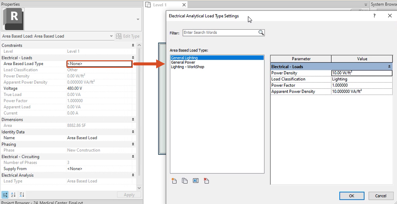
- For each area-based load type name, define the power density, load classification, power factor, and apparent power density. In this example, use the default values.
- Click OK.
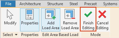
- Back in the ribbon, select Finish Editing.
Notice in the System Browser that the Area Based Load now displays under Unconnected.
- Select the load, and then rename it, either in the System Browser or in the Properties palette under Identity Data.
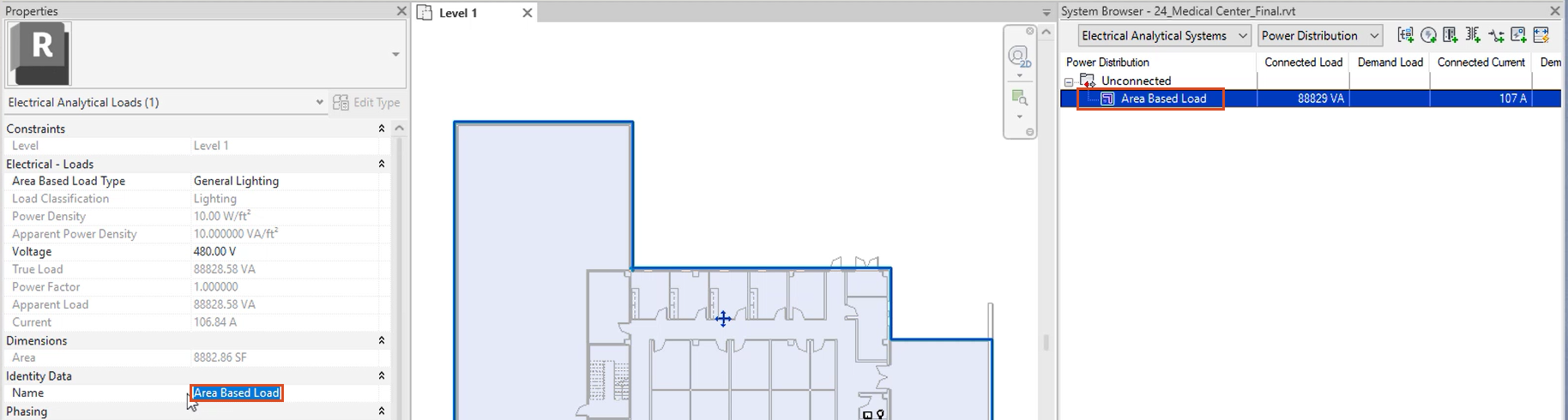
- In the Name field, enter a descriptive name, such as “LTG” for lighting in this example.
Now that the area for the load has been defined, the next step is to define the analytical system components.


