00:03
When preparing to import an InfoDrainage file into Civil 3D,
00:07
after you have configured the coordinate system, template, and project units,
00:12
you must set the pipe network catalog.
00:15
The pipe networks featured in Civil 3D reference a part catalog and a parts list that define the size, shape,
00:21
and behaviors of the pipes and structures that you insert into drawings.
00:26
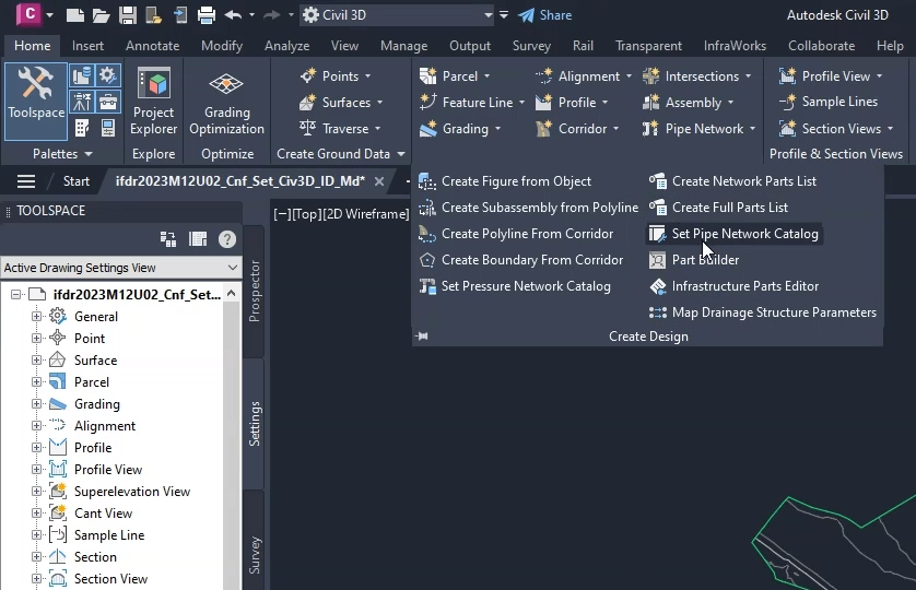
On the ribbon, Home tab, Create Design panel, click Set Pipe Network Catalog.
00:33
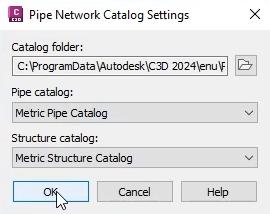
In the Pipe Network Catalog Settings dialog,
00:36
expand the Pipe catalog drop-down and select the Metric Pipe Catalog for this exercise.
00:42
Then, expand the Structure catalog drop-down and select the Metric Structure Catalog.
00:49
Next, you need to create the parts list,
00:52
which is a focused subset of the pipe network catalog.
00:55
It will include the specific parts you will use in the pipe network.
00:59
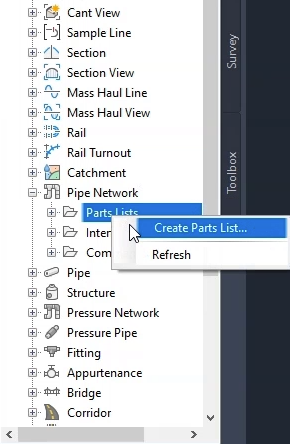
In the Toolspace, click the Settings tab.
01:02
Under Pipe Network, right-click Part Lists and select Create Parts List.
01:08
The Network Parts List – New Parts List dialog opens.
01:13
Click the Information tab.
01:16
For the Name, type “InfoDrainage specific”.
01:19
Then, click the Pipes tab.
01:22
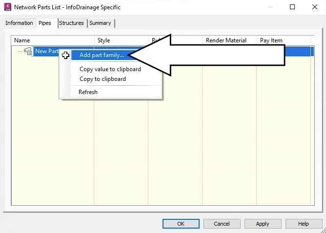
Note that the name of the dialog box updates to match the name you entered.
01:26
Right-click New Parts List and click Add part family.
01:31
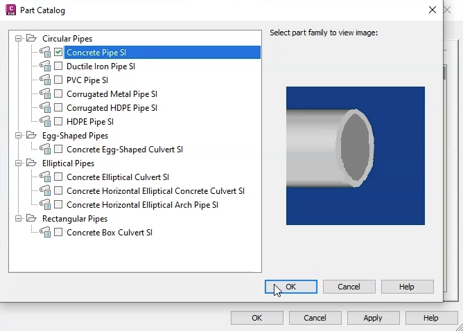
The Part Catalog opens.
01:33
Choose the Concrete Pipe SI part family, and then click OK.
01:38
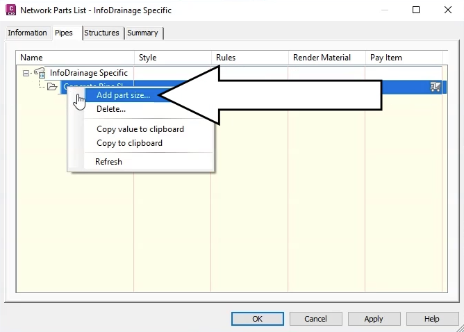
Back in the Network Parts List – InfoDrainage Specific dialog, click the Pipes tab.
01:45
Under Name, expand the node and ensure Concrete Pipe SI is highlighted.
01:50
Right-click it and select Add part size.
01:54
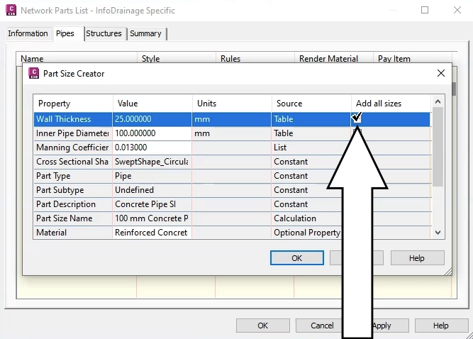
Then, in the Part Size Creator, in the table next to Wall Thickness,
01:58
ensure that the Add all sizes option is enabled.
02:02
Do the same for the Inner Pipe Diameter row as well.
02:07
Repeat this process to add the structures parts.
02:11
Click the Structures tab.
02:14
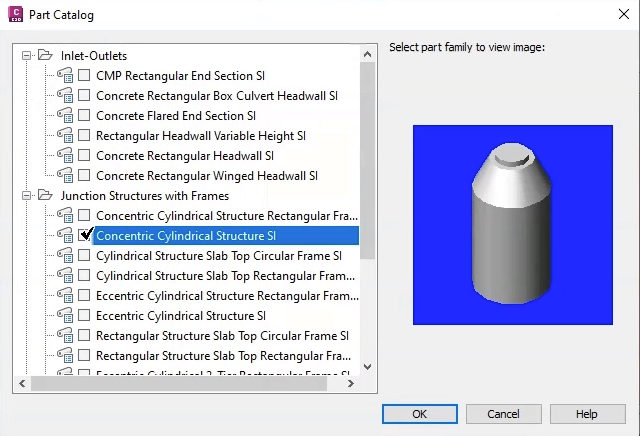
Again, right-click New Parts List and click Add Part Catalog.
02:19
This time in the Part Catalog, add the family Concentric Cylindrical Structure SI.
02:27
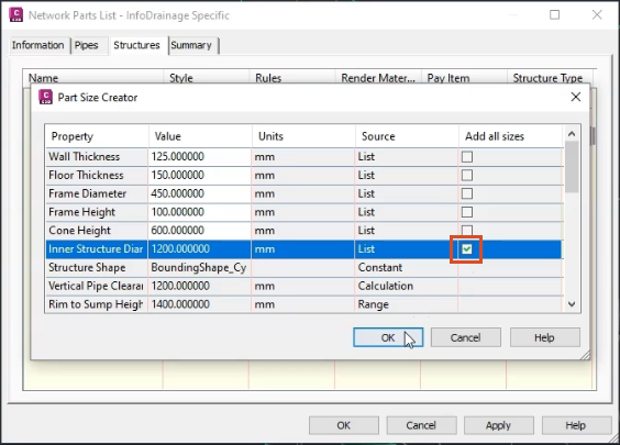
Back in the Structures tab, right-click it and select Add part size.
02:33
Then in the Part Size Creator, in the table next to Inner Structure Diameter,
02:40
enable the Add all sizes checkbox.
02:42
Be aware that the sizes provided in the parts catalog are all standard sizes.
02:48
If you have non-standard pipe sizes in your network,
02:51
you would need to use a different procedure.
02:54
Also, parts lists are saved with the drawing file,
02:57
but you still must designate the catalog that those parts lists reside in.
03:01
This is why the parts lists are subsets of the catalog.
03:04
For this exercise, save the file as “Surfacecreated.dwg”.