00:04
When you are importing and exporting surface data between Civil 3D and InfoDrainage,
00:08
it is very important to set up the coordinate system properly.
00:11
Often, when users run into problems with model objects and surfaces not lining up,
00:17
it is because the coordinate system has not been configured correctly.
00:20
The project units and the template also must be correct to ensure a smooth data exchange.
00:27
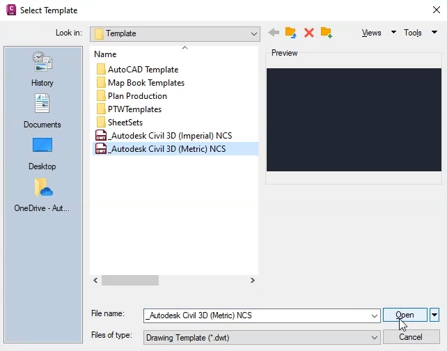
In Civil 3D, the first step is to choose the template.
00:30
Click Start > New > Browse Templates, and for this exercise, select Metric templates.
00:38
Be aware that this example is located in the United Kingdom, specifically, in Great Britian.
00:44
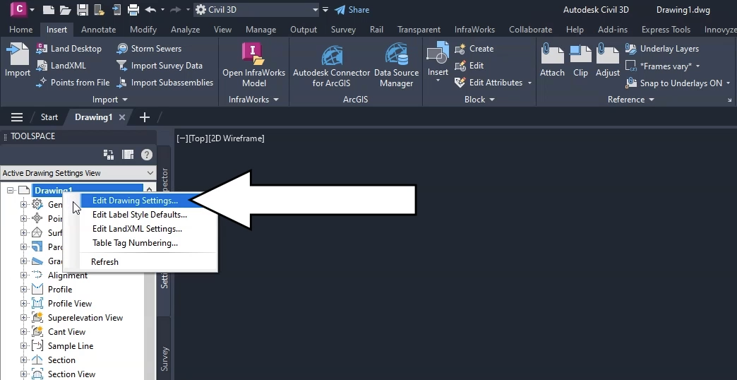
Next, set up the UK grid coordinate system.
00:47
In the Toolspace, click the Settings tab, then right-click the current drawing
00:52
and select Edit Drawing Settings.
00:55
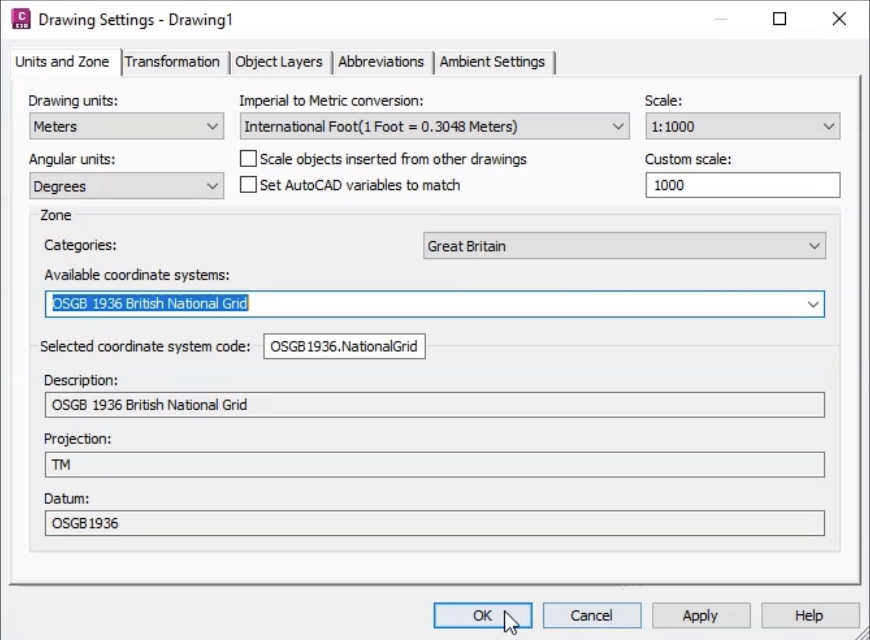
In the Drawing Settings dialog, you must set the categories and coordinate system according to your local standards.
01:02
For this example, under Drawing units, select Meters.
01:07
Under Angular Units, select Degrees.
01:11
Ensure that the Imperial to Metric conversion drop-down shows as International Foot,
01:17
and that the Scale is set at 1:1000.
01:20
In the Zone group, expand the Categories drop-down and select Great Britain.
01:25
Also, the Available coordinate systems, Selected coordinate system code,
01:30
and Description should all be set to OSGB 1936 British National Grid.
01:37
Next, you need to set up the surface data that is used to define, among other attributes,
01:42
manhole cover levels and pond perimeter levels.
01:45
On the ribbon, Insert tab, Import panel, click LandXML.
01:52
Browse to and select the file Road1.xml from the dataset.
01:58
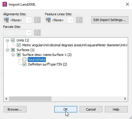
In the Import LandXML dialog, in the tree view,
02:02
expand the Surfaces node and the Surface description node,
02:06
and ensure that the SourceData node is deselected.
02:11
If any information boxes appear, close them.
02:15
The surface model appears in the drawing window.
02:19
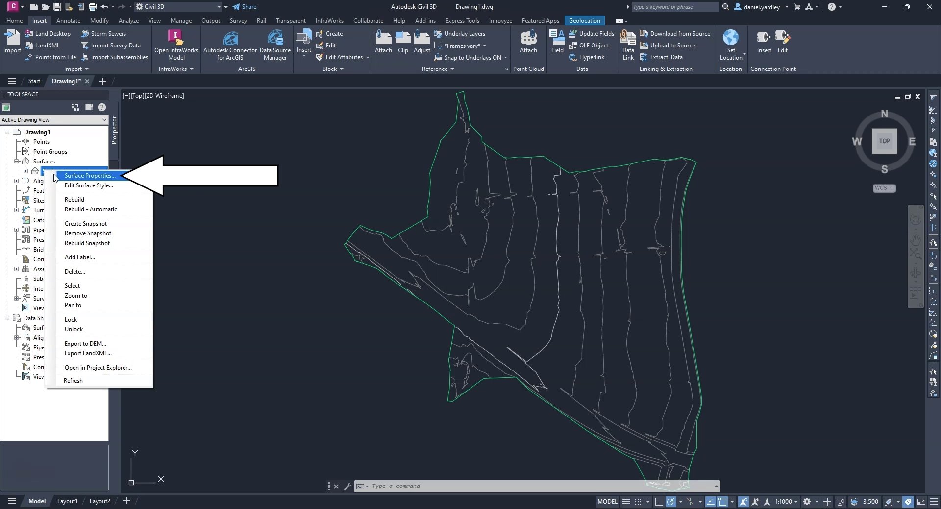
In the Toolspace, click the Prospector tab.
02:22
Expand Surfaces, and then right-click Surface1 and select Surface Properties.
02:29
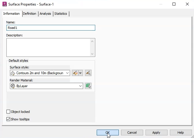
In the Surface Properties dialog for this surface,
02:32
you can edit the surface properties to change the name of the surface.
02:36
Rename it “Road1” to match the surface data.
02:40
Optionally, you can add a description or edit its default styles,
02:44
but for this exercise, leave them as-is and click OK.
02:48
The template, coordinate system, and surface file are now all configured.
02:53
Again, for your local projects, you would configure these settings to match your local standards.