00:03
When you are working with a Civil 3D project file that you intend to bring into InfoDrainage,
00:08
after you have configured the drawing template and set the coordinate system and parts lists,
00:13
the next step is to import the location data of the pipes and manholes that are to be created.
00:18
In the Toolspace, click the Prospector tab.
00:21
Then, open the file Pipe outline.dwg in a new drawing tab.
00:26
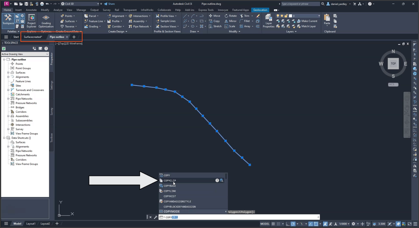
In the Pipe outline drawing, highlight all the pipes to select them, and copy them to the clipboard.
00:33
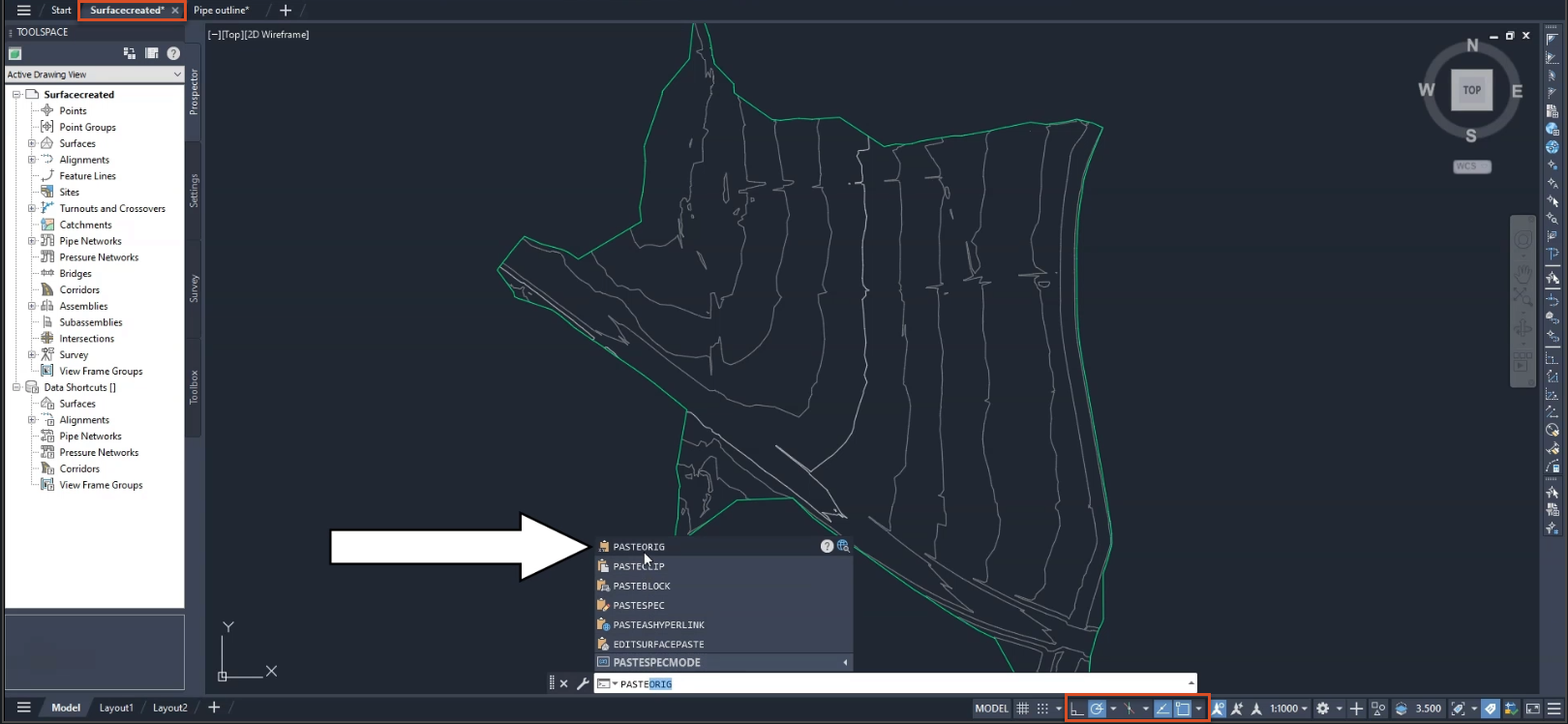
Then, paste the pipes into the Surfacecreated.dwg drawing.
00:39
Be sure to use the PASTEORIG command, so that the origin lines up and the pipes are placed correctly.
00:46
Make sure the Snap tools are on.
00:50
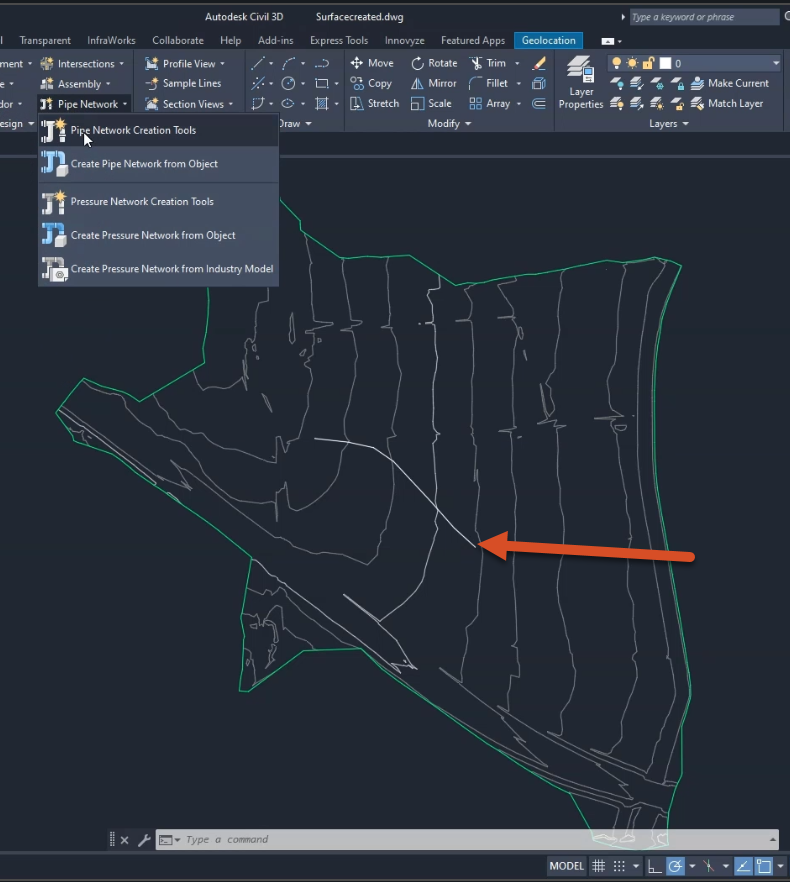
On the ribbon, Home tab, Create Design panel, expand the Pipe Network drop-down and select Pipe Network Creation Tools.
00:59
Or, in the Prospector tree, expand the Pipe Networks collection, then right-click the Networks collection,
01:05
and click Create Pipe Network By Layout.
01:09
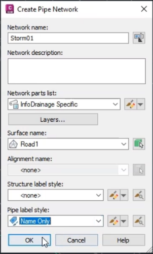
In the Create Pipe Network dialog, enter a unique Network name.
01:14
For this exercise, name it “STORM01”.
01:18
You have the option to enter a description for the network, but leave it blank for now.
01:23
To specify the parts list associated with this pipe network, under Network parts list,
01:29
expand the drop-down and select InfoDrainage specific.
01:34
Under Surface name, expand the drop-down and select Road1.
01:39
Keep the Alignment name to the default of none.
01:42
For the Structure Label Style, keep the default of none, and for the Pipe Label Style, select Name Only.
01:50
The Network Layout Tools toolbar is displayed,
01:54
and the pipe network name is displayed under the Pipe Network collection in the Prospector tab.
01:59
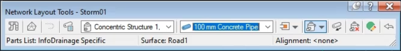
Here, in the Network Layout Tools toolbar, you select the parts you want from the Pipe List and Structure List.
02:06
For this exercise, expand the Structure drop-down and select the Concentric structures.
02:12
Then, ensure that the 100 mm Concrete Pipes are selected.
02:17
However, be aware that it does not matter what size you select for the the structure and pipe elements,
02:22
as these will be designed in InfoDrainage.
02:25
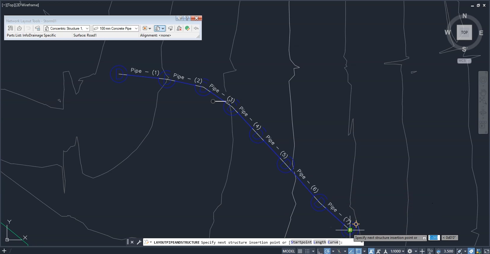
In the drawing, create the network.
02:29
Make sure the Snap tool is ON and zoom into the drawing.
02:32
Hover the cursor over the end of the pipe network, and the manhole highlights.
02:37
Click to create the first structure, then continue clicking along the line,
02:42
being careful to click every manhole.
02:45
Press ESC to finish, and the network is complete.
02:49
Save the file as “Pipesandmanholes.dwg”.