Step-by-step:
One type of sustainable drainage solution (SuDS) is a swale. Swales can be manmade or natural, and often take the form of shallow channels in low-lying areas. InfoDrainage gives you several options for designing swales and adjusting their infiltration rates and volumes.
- Open a file that contains a swale, such as Swale design.iddx.
- In the ribbon, Plan tab, Modes panel, enable the Snap mode.
- In the Toolbox, click the Select tool.
- In the Plan View, zoom into the outline of the swale.
- Click the pipe inside the outline for the swale.
- Press DELETE.
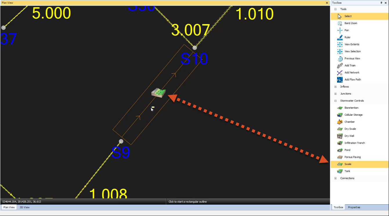
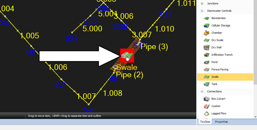
- In the Toolbox, expand the Stormwater Controls node.
- Click and drag the Swale icon to the swale outline in the Plan View and drop it somewhere inside its boundaries.
Notice that the cursor changes to show it can be used to digitize the outline of the swale.
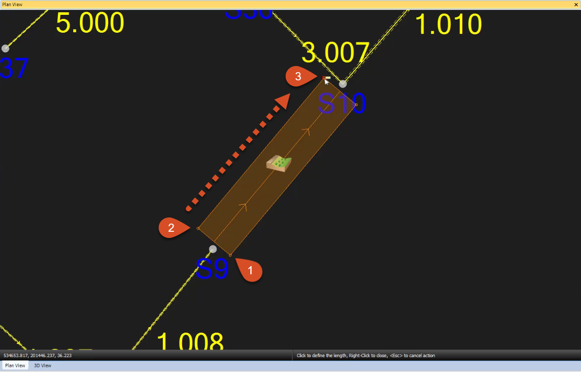
IMPORTANT: Unlike other types of structures—like ponds, for example—the order in which you digitize the corners of a swale must be deliberate because you must specify dimensions for length and width.
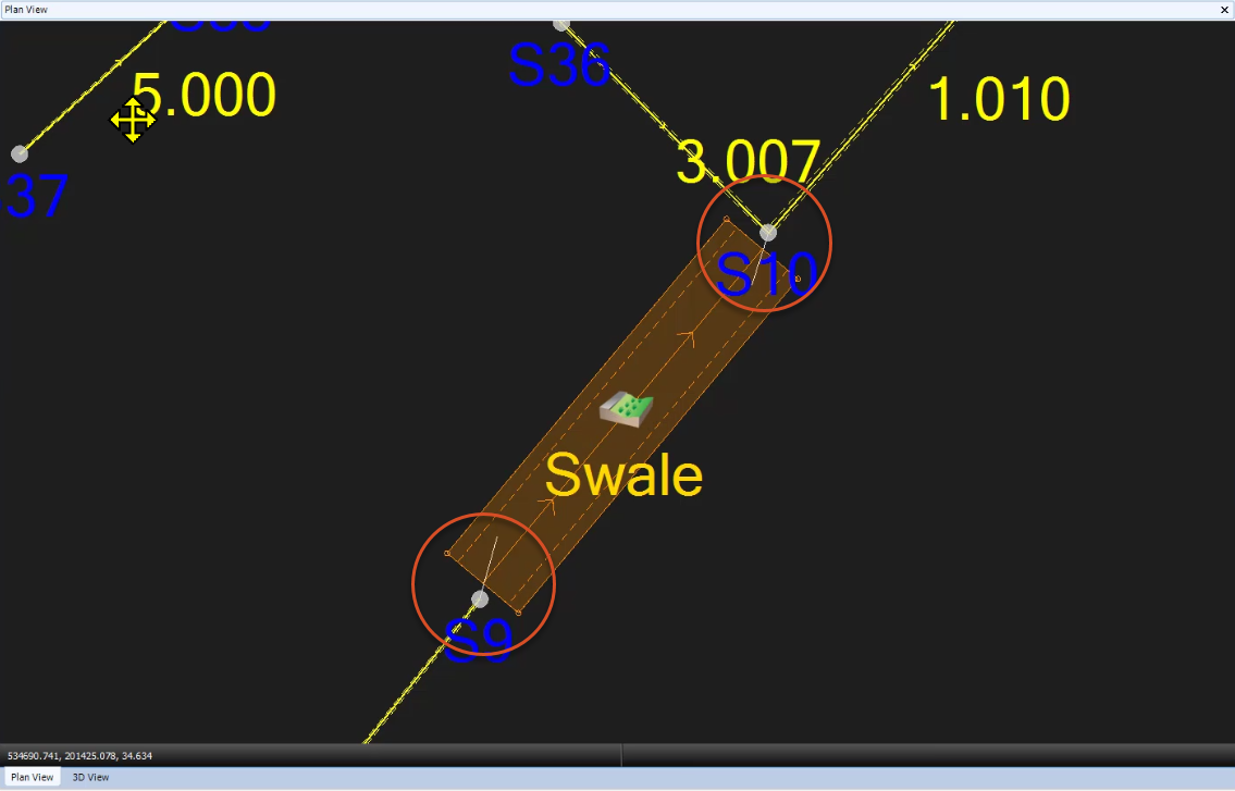
- To digitize the swale outline, click the upstream corner just to the right and below manhole S9.
- Then, click the other upstream corner. At this point, the digitization cursor locks to the width dimension with an adjustable length.
- Drag the cursor downstream to the other end of the swale and click again to complete the swale.
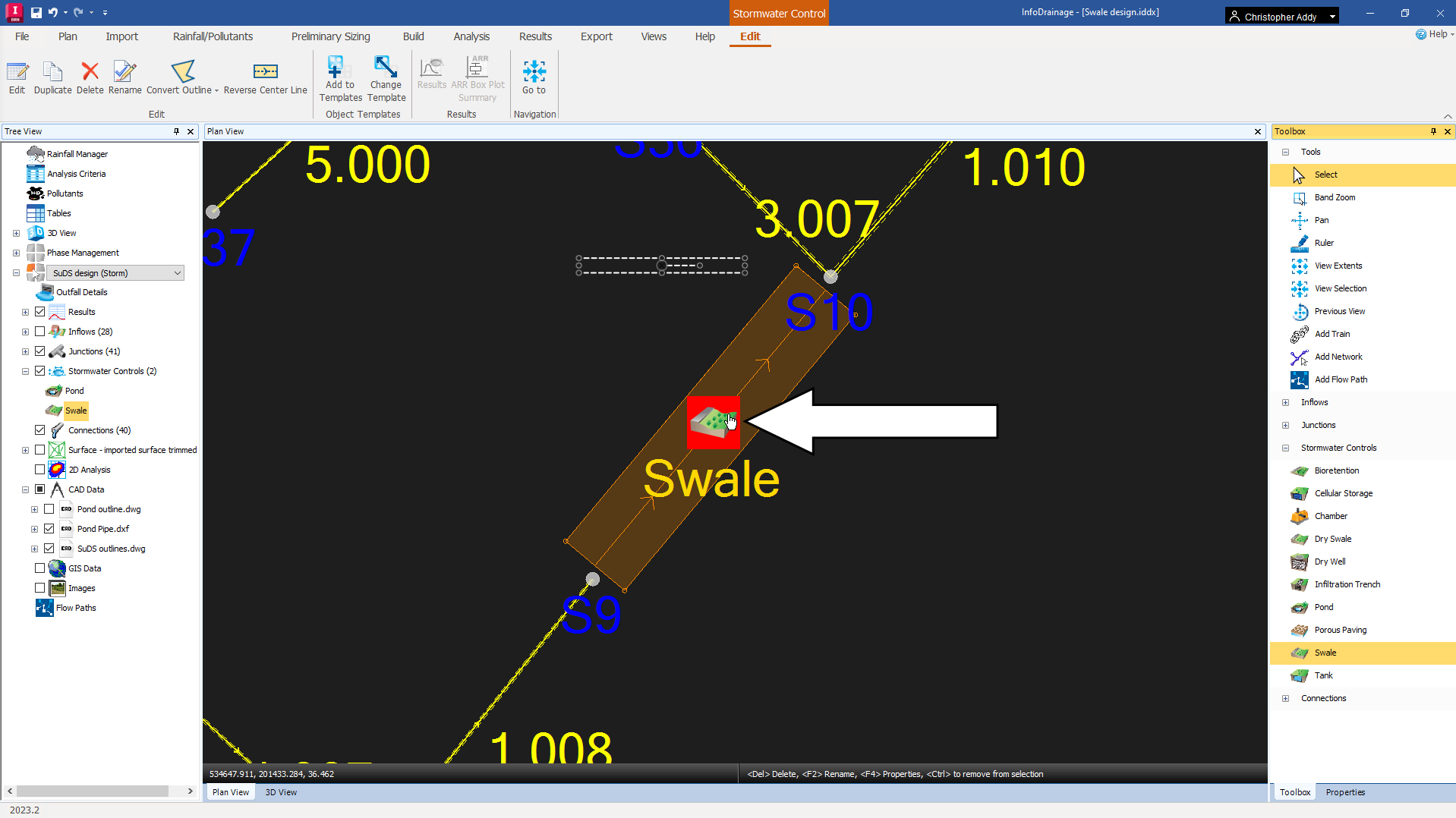
- Click the Select tool to end the swale creation.
- Double-click the Swale icon to view its properties.
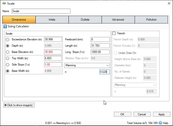
- In the Swale dialog box, toggle ON the Depth field.
- For the Base Level, enter 35.
- Set its Side Slope to 1.
- Enter a Longitudinal Slope of 1000.
- Enter a Manning’s n (roughness) value of 0.020.
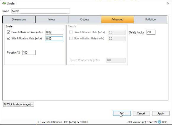
Another defining characteristic of SuDS structures is that they allow water to permeate out of them into the surrounding soil, so you must set infiltration rates. This swale will permeate through both the bottom and sides of the swale.
- Click the Advanced tab.
- Enable the Base Infiltration Rate. Set it to 0.02 meters per hour.
- Enable the Side Infiltration Rate. Set it to 0.02 meters per hour.
- Close the dialog box.
- The swale must now be connected to the rest of the network. In the Tree View, right-click CAD Data and select Import Data.
- In the Load CAD Wizard, click Select.
- In the Open dialog box, navigate to and select SuDS pipe.dxf. This file serves as a background CAD layer that defines the location of the connecting pipes.
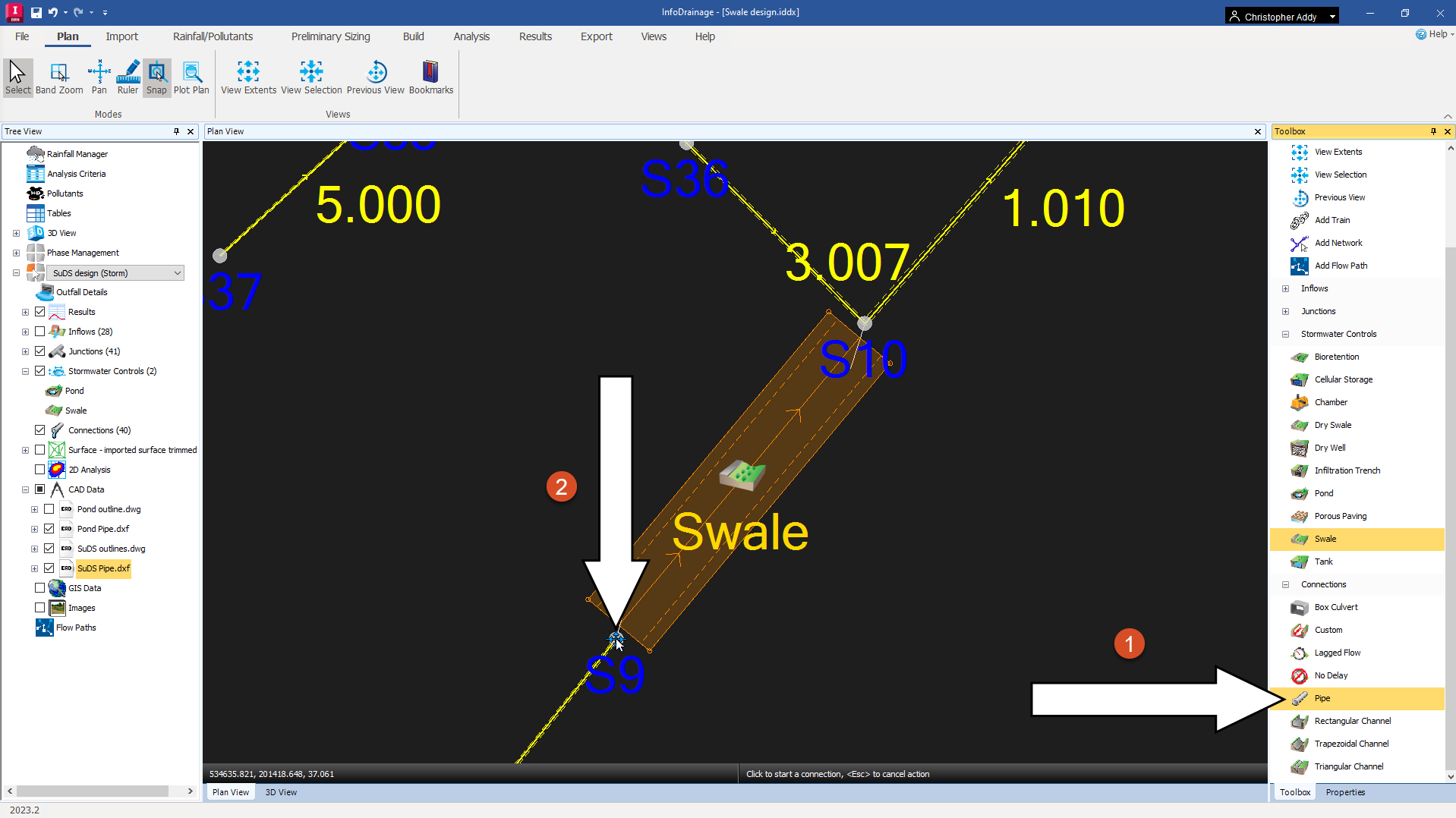
- In the Toolbox, expand the Connections node.
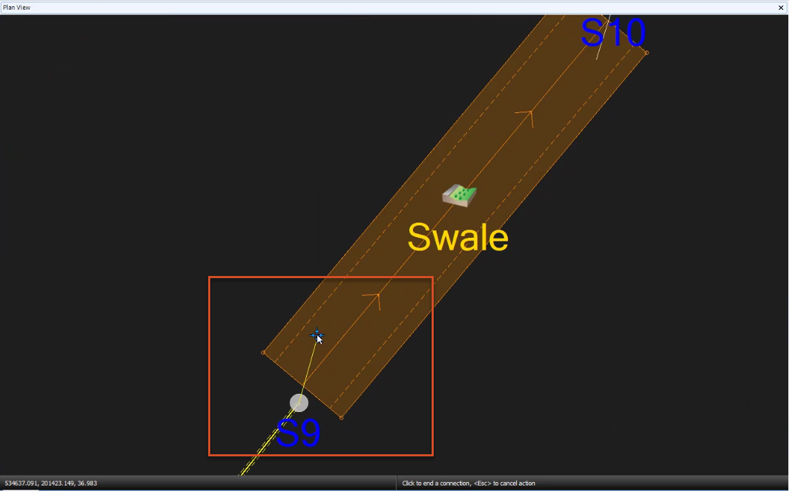
- Click and drag a Pipe onto manhole S9.
- Connect the downstream end of the pipe to the end of the background pipe.
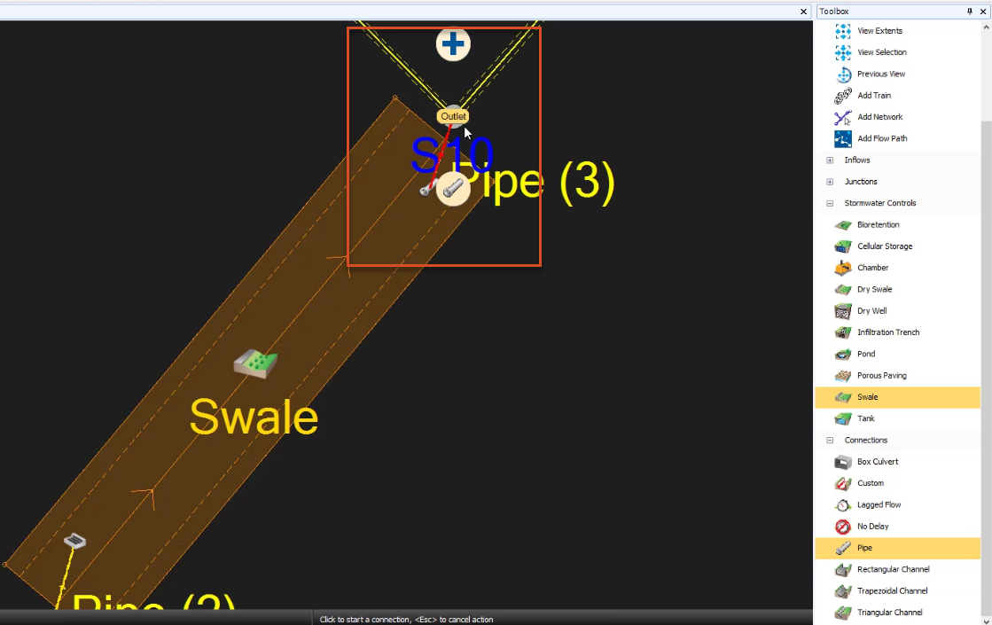
- From the Toolbox, click and drag another Pipe onto the image of the pipe leaving the swale.
- Connect the downstream end of the pipe to manhole S10.
- Click the Outlet option.
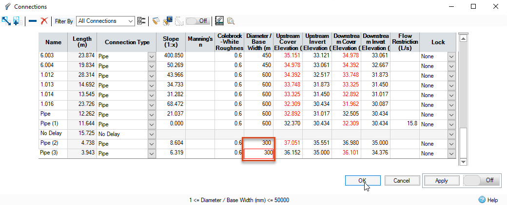
- Using the Select tool, double-click either of the new pipes.
- Set the diameters of both pipes to 300 mm.
- Click OK.
You will use an orifice to control the discharge from the swale. It must be designed in a way that maximizes the swale’s storage capacity without causing flooding. In this case, the swale has a volume of 184.189 cubic meters. The task, therefore, is to define an orifice diameter that limits the discharge such that this amount of storage is utilized during the 1-in-30-year design storms.
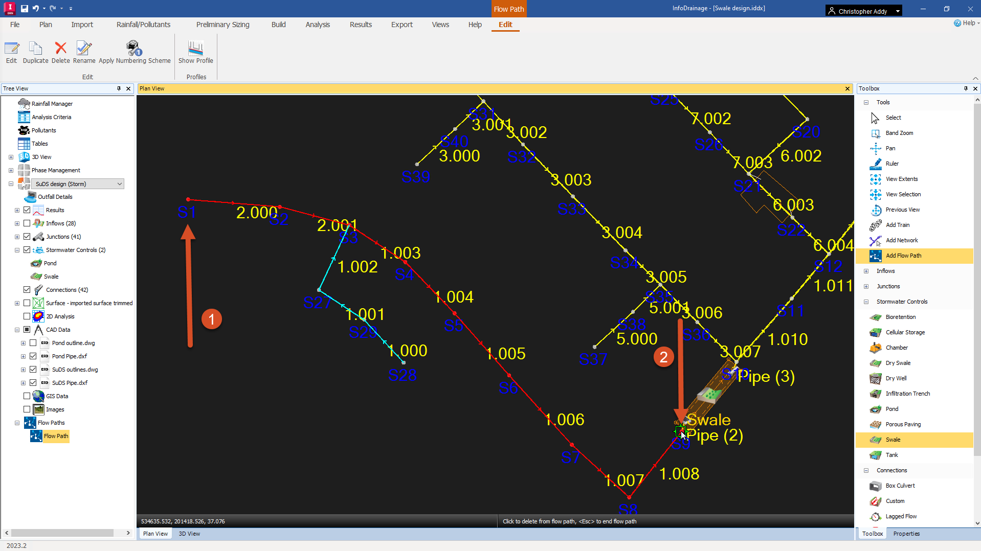
- In the Tree View, right-click Flow Paths and click Add.
- Click manhole S1 to start the flow path, and then manhole S9 to complete it.
- In the ribbon, Results tab, Reports panel, click Inflow Summary.
- In the Inflow Summary dialog box, note the Area Analyzed value of 0.654 hectares.
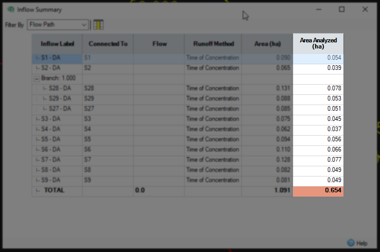
- Close the Inflow Summary.
- On the ribbon, Preliminary Sizing tab, Calculators panel, select Quick Storage Estimate.
- In the Quick Storage Estimate dialog box, set the Area field to 0.654.
- Set the Volumetric Runoff Coefficient field to a value appropriate for winter, in this case, 0.840.
- Estimate a Discharge Rate of 6.0 liters per second.
- Enter an Infiltration Rate of 0.02.
- Enable SRP Wizard FSR.
- Click Calculate.
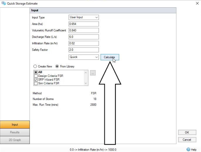
The displayed results tell you that with infiltration and the discharge rate you just set, the swale’s storage should be somewhere between 128 and 217 cubic meters.
- Click the Input tab.
- Change the Discharge Rate to 4.
- Click Calculate again.
The Results should now report a range with infiltration of 136 to 232 meters cubed.
- Click OK.
- Click the Select tool.
- In the Plan View, double-click the Swale icon to view its properties.
- In the Swale dialog box, click the Outlets tab.
- Expand the Outlet Type drop-down and select Orifice.
- Click Calculate Diameter.
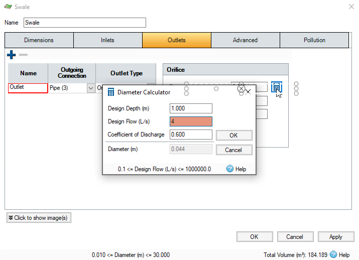
- In the Diameter Calculator, set a Design Depth of 1 meter.
- Set a Design Flow of 4 liters per second.
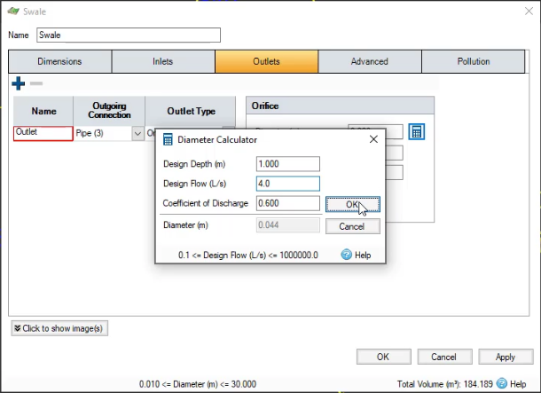
- Click OK to close the calculator.
- Click OK again in the Swale dialog box.
- In the ribbon, Analysis tab, Criteria panel, click Analysis Criteria to verify the criteria are correct.
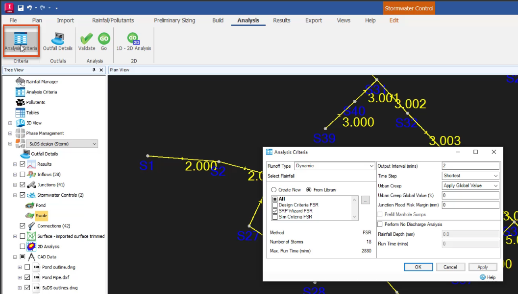
- Click OK to close the Analysis Criteria dialog box.
- In the Analysis panel, select Validate.
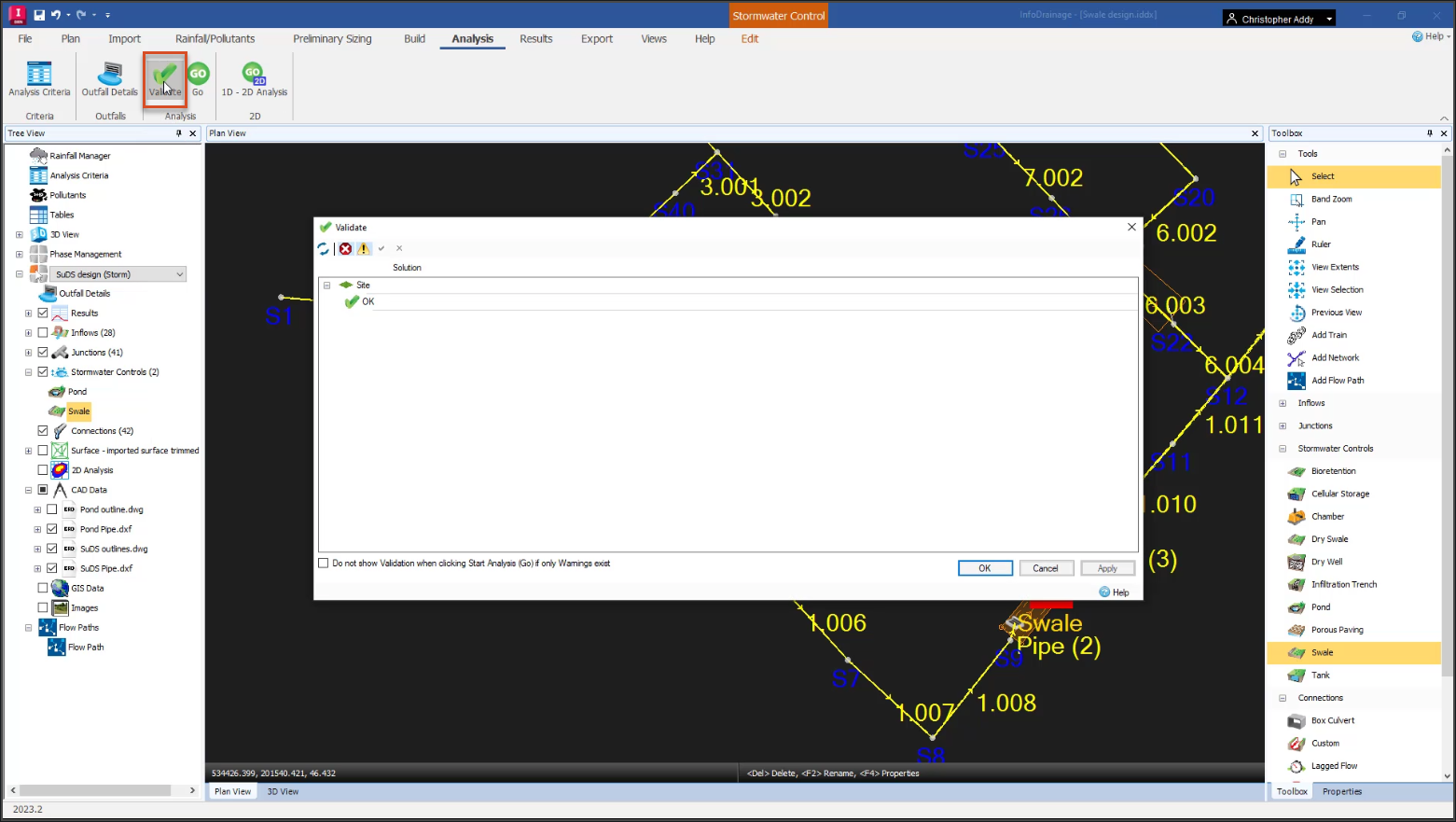
In this example, there are no errors.
- Click OK to close the results.
- Save the file.


