
The Smisto Hydropower project is a new hydropower project currently being constructed in Norway. It has become one of the first projects challenging the traditional use of 2D drawings as a design basis in a project. It comprises two individual high head power plants, both with a low discharge and a large reservoir capacity.
This article focuses on the use of 3D/BIM-models in the design and construction processes, with an emphasis on communicating the design to the contractor for civil and underground works without the use of conventional 2D drawings. Under an EPC contract arrangement, the continuous interaction between the contractor and the consultant has led to the development and implementation of several BIM-strategies for the engineering, design and construction works with several benefits experienced for the execution of the project.
We'll explore the following regarding integrated use of 3D/BIM-models in design and construction through collaboration and innovation in order to achieve working without drawings:
1. Is it possible with technology today?
2. Is it desirable to users?
3. Is it viable?
Background
The Smisto HPP
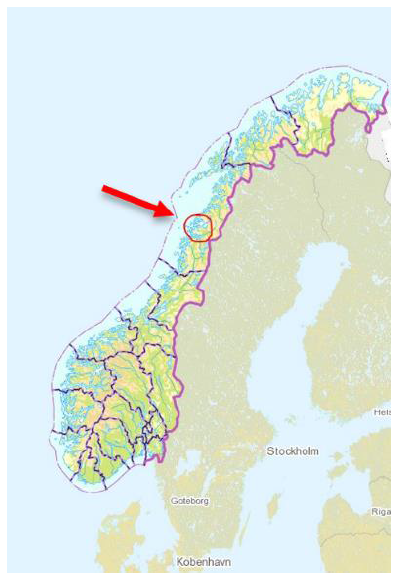
The Smisto Hydropower project is one of the major new hydropower projects being constructed in Norway since the beginning of the 20th century It comprises two separate high head power plants with low discharge and a large reservoir capacity. The two power plants, Smibelg of 33MW and Storåvatn of 25 + 8MW, is located in Nordland in the north of Norway. The construction works started in the summer of 2015 and the commissioning of hydroelectric generation is to be completed in three stages during 2019.
The main features of the project include a total of 27 km of unlined underground waterways through tunnels and shafts, two underground power stations, eleven intakes, a pump station and six underwater tunnel piercings in addition to several smaller dams.
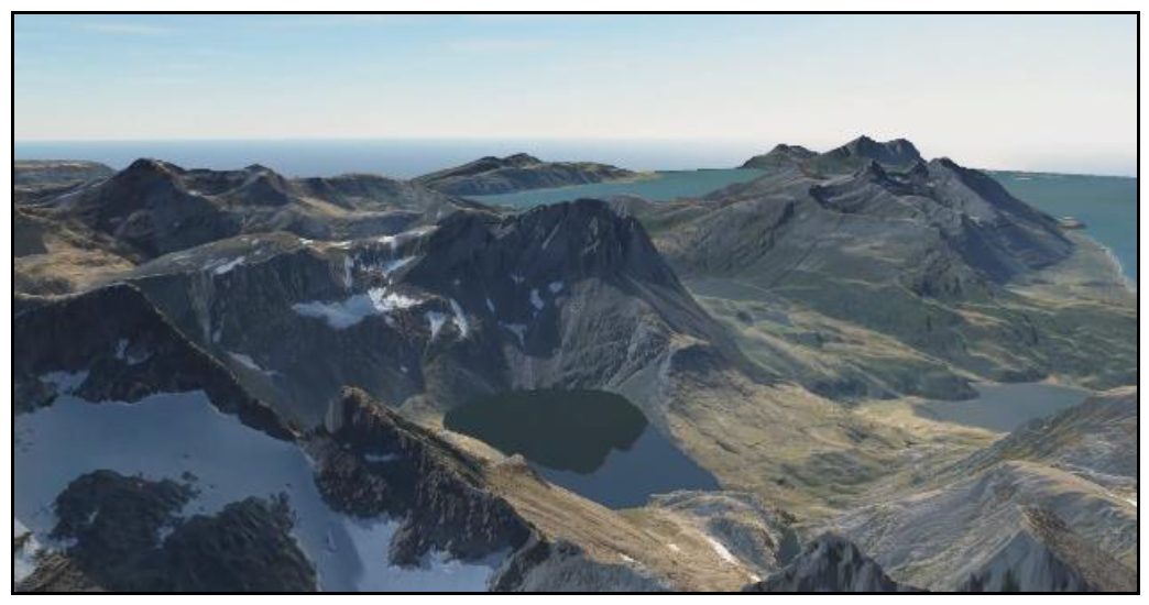
The project is located in a remote coastal area with great climatic variations between the fjord and mountains in terms of wind, rainfall and temperature. The site is only accessible by sea with most of the intake sites only accessible by helicopter, something that places great demands on both the planning and logistics of execution.
Basis for Execution of the Project
The project owner Smisto Kraft AS awarded the contract for execution of all civil and underground works to the Norwegian contractor Hæhre Entreprenør AS under an EPC contract arrangement. The hydromechanical and electromechanical equipment are provided and installed by suppliers, contracted and coordinated by the project owner. The Engineering, Procurement, and Construction (EPC) contracting arrangement implies that the EPC Contractor is made responsible for all the activities from design, procurement, construction, to commissioning and handover of the project to the project Owner.
On behalf of the contractor, Multiconsult ASA are carrying out the design and consultancy for all civil works in addition to coordination towards the different hydromechanical and electromechanical suppliers, contracted by the project owner.
The use of EPC contracts for civil works is unconventional for the execution of Norwegian hydropower projects, where the consultant traditionally performs the design on behalf of the project owner. Nevertheless, the EPC setup in the project has created an opportunity for expanded collaboration between the EPC-contractor and the consultant. Through early clarification rounds, the two parties managed to unite their goals for the project execution, with a focus on continuous interaction in order to achieve:
• Cost-effective technical solutions
• Efficient execution on-site
• Efficient workflows from concept to construction
• Fulfillment of required plant performance and documentation of the construction works
As a supplementary common ambition with potentially high excess value for both parties, it was decided to challenge conventional methods for both design and construction by carrying out all design and drawing works in 3D/BIM-models. Further to this, the design is communicated to the contractor via the models, without the need of preparing traditional 2D drawings.
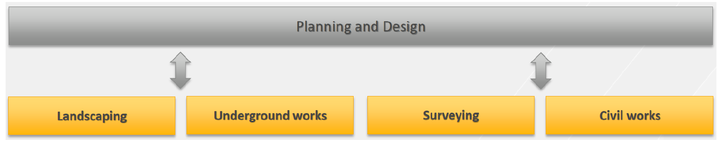
Planning and Design Process
The unusual contracting arrangement in combination with the unconventional communication of design to the contractor via 3D models introduced the need of changes in the planning and design process. Changes both in terms of the workflow but also in the use of tools has been identified.
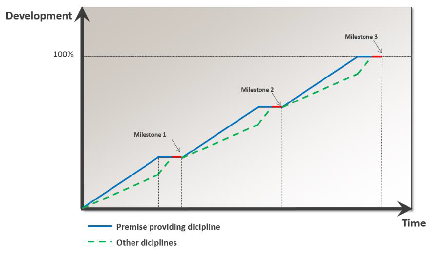
A design process is an iteration between the involved disciplines, one always being the premise providing discipline. By applying a linear approach for structuring the overall processes into sub-phases, where work on the next phase is not started until a certain milestone is attained by all disciplines, smaller iteration cycles and a more streamlined design process is attained.
The workflow for the project execution is based on the Multiconsult philosophy, but is adapted in order to achieve the project specific goals. The final workflow that has been applied include the following consecutive sub-phases:
1. Initialization of design works
2. Interdisciplinary design process
3. Detailed design
4. Follow-up of construction works
The sub-phases define the involvement of the contractor, suppliers and project owner throughout the process, in addition to what work to be done, in what order and until what level of detail.
The suggested workflow has proved to streamline the design works, and also reduce the number of revisions typically involved in similar projects. Both of these advantages result in cost reductions. Further to this, the new workflow offers an improved platform for project planning and follow-up, as it is visualized in specific quality levels as described in Chapter 4.
Methodology for Development and Implementation of Model-based Execution
To accommodate for the ambition of direct retrieval of information from 3D/BIM-models at the construction site without any preparation of traditional 2D drawings, it was focused on potential improvements of conventional methods within the following areas:
• Different use of existing software for both design and construction
• Rationalizing the way information is transferred from the consultant to the contractor, based on utilization
• New products, replacing the traditional 2D drawings
• Allow for extended communication through models
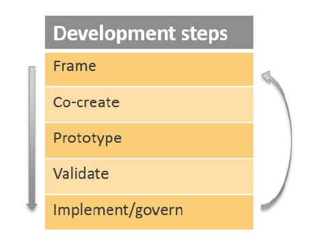
To develop and implement concepts where usability at the construction site is in focus throughout the design phase, the mind-set of a Braided Design Model was applied. This model was chosen because it aligns design, strategy and use of technology through five consecutive development steps, and through several iterations.
With both parties involved in the continuous development of different concepts, it gave the ability to consecutively test functionality at the construction site and iterate towards new concepts that has led to several developments, as further described in this paper.
How Models Are Being Used
In combination with geometry, a certain set of properties must be defined for a designed civil element to form a representation of what is to be constructed. On a traditional 2D drawing, geometry is given as plan views and sections with reference to coordinate points, while specifications on the drawing provide information on materials, installation techniques, and quality standards.
Differently from a 2D drawing, a 3D model provides the complete element geometry and location in final coordinates. Combined with assigned properties for each element, the 3D model forms a digital representation of the design.
For the Smits project, it was decided to define a customized set of information parameters and properties. This information is designated to each modelled element and include: Quality level, sequencing, element ID, design provision, explanations, fire resistance requirements, material requirements, quantities, etc.
Combined with element geometry, the information parameters make all information from the design available when needed, with the only, but significant, barrier being the necessary use and understanding of a computer program at the construction site. To structure and facilitate for the retrieval of information, the models are prepared and coordinated in a hierarchy as follows:
1. Compilation model
• Illustration of overall composition and control of exterior interfaces between rock- and concrete works
2. Integrated models for each main structure (e.g., power plant, dam) in the Colibri Software
• Interface handling, clash detection and interdisciplinary coordination
• Construction simulation • Work instructions for civil works
3. Design models, Autodesk Civil 3D for tunneling and landscaping works and Revit for all other structures
• Export of IFC-models to the integrated models
• Export of specific models, enabling for the direct retrieval of surveying data at the construction site
Sequencing
As previously described, the hydromechanical and electromechanical equipment are provided and installed by suppliers contracted by the project owner, with contractual requirements of detailed design being provided through 3D-models. Combined with the structured civil structural models, the supplier’s models allow for physical interface handling, clash detection at an early phase and interdisciplinary coordination in the integrated models.
The civil structures are labelled according to the planned construction sequence and combined with the supplier’s individual models based on installation order. This labelling system allows for a more advanced coordination of construction and installation sequencing in the design phase.
Quality Levels
In order to control the described planning and design process in a model, the development of all components is structured into specified quality levels, illustrating the status and quality achieved regarding design, interdisciplinary control and construction status of each element. The current quality level is visualized together with the planned construction sequence in the integrated models.
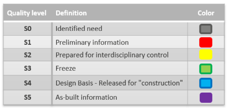
The civil structures are labelled and developed according to planned construction sequences. Combined with the quality levels, the achievement of functionality is ensured, and the visualized development of the process offers a great platform for project planning and follow-up, in addition to a communication platform for all involved parties.
At the intersection between design and construction, the complete structure is provided in the models to visualize the totality, but the contractor cannot commence with any components labelled lower then S4.
The label S5 is given to elements completed on site where the execution is controlled and in correspondence with the design according to the contractors control system, including surveying of the executed elements. Where execution has deviated from the design, the models is adjusted accordingly before the label S5 is given. The continuous upgrading to “as built”-documentation will potentially create a functional tool for operation and future maintenance works of the hydropower plant.

The quality level describes the maturity of each element in the design process and does not correspond to a certain level of detail or information. The level of detail and information in modelling are carried out until the appropriate level for construction, agreed upon between the parties before the design process starts. In theory, an element can pose a high degree of detail in an early phase even though it is not sufficiently prepared for construction. On the contrary, an element may exist without geometric details, yet with sufficient information for the purpose of construction.
Adaptation of Design Basis According to Execution
The design models are prepared and coordinated as presented for the model hierarchy in order for the correct information to reach both the contractor’s site management, as well as the construction workers. With modern equipment at the construction site, including equipment for machine control and surveying, 2D drawings is not always the most efficient form of communicating design basis for execution. This requires different approaches for the different features of the project, taking into account the characteristics of different software and the planned method of execution:
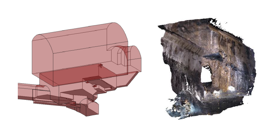
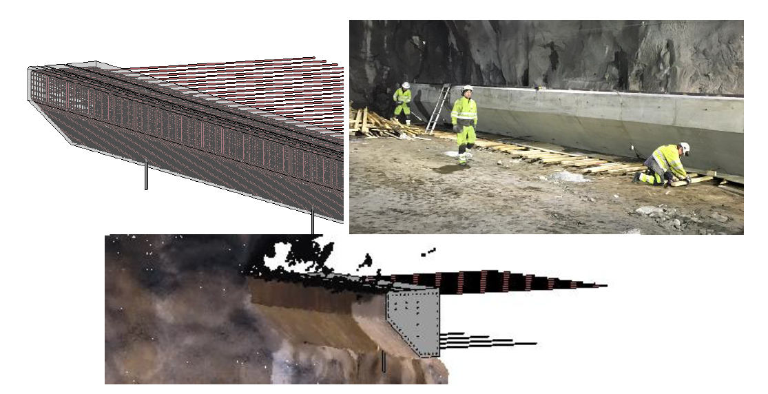
• Models prepared for tunnels, landscaping and excavation of rock caverns where machine control is central in the execution
• Models for the concrete works, reinforcement and other installations in the power stations with the need of detailed geometric control and assembling procedures
Where it is not needed with the allocation of more than one property in addition to geometry, the Autodesk Civil 3D software is used for the design of the following features of the project:
• Shafts and tunneling works; defining the centerline and cross-section requirements, needed for the contractor to prepare drilling plans
• Landscaping works; defining shape and barriers
Autodesk Revit software is used for all other features of the project. This software is chosen because it allows for the structured allocation of properties of 3D elements. Revit is used for the design of the following main features:
Underground work:
• Rock caverns and cuttings; defining volume of blasting and minimum outer boundaries to facilitate for the preparation of drilling plans
• Rock bolts; defining depth, location, orientation, and dimensions of the bolts and requirements for execution.
All other civil work, including:
• Concrete form and reinforcement, including embedded details, block outs, etc.
• Technical installations such as earthing, light electrical installations, heating, ventilation and sanitation
The direct flow of information through the models forms the basis for all communication about design, including design meetings. In addition, model viewpoints also form the basis for communicating issues, mark-ups and questions between the parties directly in the models through BCF files.
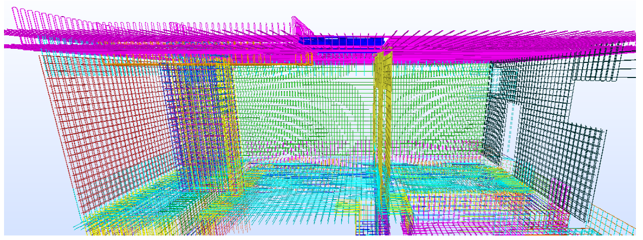
Design Basis for Concrete Work
For the concrete works, all elements are modelled according to the planned casting sequence, including construction joints. This gives an accurate basis for design works such as impacts on the structural calculations, correct specification of reinforcement bar length and splice locations. As a supplementary benefit for the contractor through direct quantification, it provides the possibility for construction planning and procurement at an early stage.
For concrete works, the complete design basis is implemented in the integrated models for the structure. However, to facilitate for the retrieval of information, increasing the availability, a sorting of information is provided in the models by the following measures:
• A combined set of model viewpoints for each construction sequence, displaying planned sub-sequencing and highlighting of critical information such as block outs and embedded parts
• Bar bending schedule
• Relation between concrete element ID and reinforcement bars. The reinforcement (and other relevant details such as embedded parts, inclination of floors) is assigned to its hosting concrete elements.

Conclusions
Through continuous interaction between contractor and consultant, several BIM strategies in the engineering, design and construction works has been developed and implemented in the execution of civil and underground works.
• Streamlined value creation from concept to construction through the integrated use of 3D/BIM models
• Modified approach for design and construction works without the preparation of traditional 2D drawings Integrated use of 3D/BIM models in design and construction through collaboration and innovation – zero drawings:
1. Is it possible with technology today?
2. Is it desirable to users?
3. Is it viable?
The BIM models, combining element geometry and information parameters, makes all information from the design phase available when needed, with the only, but significant, barrier being the necessary use and understanding of a computer program at the construction site. However, after attaining a certain competence level in using the software, the direct data flow between the parties through the 3D/BIM-models has presented significant improvements, such as:
• Minimized time-consuming manual operations, such as the need of establishing and maintaining a complete set of drawings, which also reduces possible sources of errors.
• Excellent platform for exchange and retrieval of information
• Enhanced interdisciplinary coordination and control
• Efficient tool for scheduling, this includes the design as well as the execution works
• Visual tool providing an excellent overview of a construction project
• Direct retrieval of relevant quantities at any given stage of the project and simplified volume calculations
Herman B. Smith is a civil engineer and project manager for design and consultancy works.
Gøran A. Hansen is a civil engineer and BIM manager.