Description
Key Learnings
- Learn about the methods available for creating custom bridge components for the InfraWorks-centered workflow.
- Learn how to create custom bridge components using Inventor.
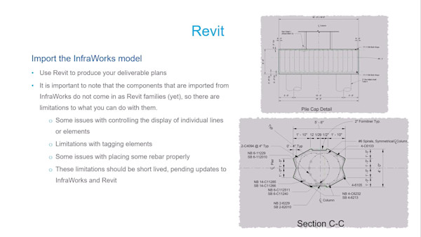
- Learn how to create custom bridge components using Revit.
- Learn about the workflow required to implement and modify the created components for use.
Speaker
- Andrew ManzeAndy's background is in structural engineering. He has also worked on a variety of novel civil and structural engineering projects over the years, before holding a combination of technical and business development positions, joining Autodesk 10 years ago.
ANDREW MANZE: Hi, everyone, and welcome to this class on Building Custom Bridge Components for Idiots. My name is Andrew Manze. I'm technical marketing manager here at Autodesk. OK, let's get started.
OK, so before we actually get into the class itself, I've just got to direct you to this safe harbor statement. And this is basically just suggesting that we may have some forward-looking statements or software in this presentation and that you shouldn't really base any of your buying decisions based on what you see today, although everything that you see, we are fully intending to deliver. But in any case.
OK, so let's have a look at what we're going to talk about today. So we are here to talk and explore the workflow with Inventor and Revit parts. But to give some context, I am going to go over briefly at the beginning where that fits into the workflow. So we'll talk about the workflow itself, which includes the main products, which are Civil 3D, InfraWorks, Inventor, Revit, and Structural Bridge Design and/or Robot.
We'll then look at the custom components. We'll explore what the different component categories are. And then we will get into the worked examples themselves for both Inventor and Revit. So we'll be looking at both methods. And this is where we'll spend most of our time doing this.
OK, so let's have a look at the workflow itself. So if you can look at this slide, you'll see that we have those products that I've just mentioned. And you'll notice that InfraWorks is in the middle. So InfraWorks is the hub for all the data that we're going to be creating. So the bridge model is created in InfraWorks, but that data can then be shared out to Civil 3D and Revit for various purposes.
So we usually start in InfraWorks. So we can create the alignment and the conceptual design and develop that all in InfraWorks. However, sometimes we might have an alignment available to us in Civil 3D, and we can bring that into InfraWorks right at the very beginning of the project and use that as the basis for the bridge as well. And as time goes on where the alignment is changed, InfraWorks can automatically update itself in accordance with that new data.
Now, that same data that we're sending from InfraWorks to Civil 3D can also be picked up by Revit for the purposes of creating the documentation. You'll notice there's also a line to Structural Bridge Design. So we can also send the InfraWorks data to Structural Bridge Design for the purposes of designing out the structure and the components building the bridge. And so also, I've got their custom parts. So that's what we're going to be looking at today where we can take parts created in Inventor and Revit into InfraWorks if the native parts that are supplied with the vanilla product aren't sufficient for your purposes.
So let's just have a quick look at the workflow itself very briefly. So we're in Civil 3D here. And we're pulling that alignment or corridor into InfraWorks. Then we can just use the bridge tools to create the initial bridge structure. We can then interact with it. It's very parametric in nature.
We can also use spreadsheets if we want to to define the geometry if the geometry is repetitive or you've got geometry dependent on formula. We can also then send that data to Autodesk Structural Bridge Design, which is running internally in this particular case at the early stages, to give us a design on those girders. And then when we move on to more complex bridges, or even just later in the stages of the design, we can send it to the full version of Autodesk Structural Bridge Design to do advanced analysis, including finite elements as you saw there.
OK, so once that's done, we can then export that data, or connect really, to Revit for the purposes of creating the documentation. So you can see it pulling the bridge there in its entirety. Any changes that we make in the InfraWorks model while documentation is being created can be sent to Revit as a managed update, and it will automatically update all the documentation.
Of course, while we're in Revit, we can do any number of document phases including rebar, general sections, elevations, and plans as you see here. And this is just the regular stuff that you would get in Revit. And then the bridge itself can be sent from InfraWorks back to Civil 3D, and that can be used to assist in grading tasks or the creation of other documentation such as long sections. Now, of course, we're in the InfraWorks product here. And for this, we can now do, of course, nice visualizations to sell our projects to other stakeholders within the project.
OK, so that's enough of the workflow really. So now, we're going to get stuck into what we're really here to talk about, which is creating these custom components. And this is part of the workflow that we're here for.
So let's talk about the custom components to start with. So there are two types of custom components. There are 2D types and 3D types. So for the simple 2D ones, these are only really applicable to decks and girders where we provide a 2D version of our custom component and then InfraWorks will automatically extrude it as necessary. So they're the very simplest forms.
But what we're here to talk about today are the slightly more complex ones where we actually create a full miniature 3D model, if you like, of the component and then take that to InfraWorks. So they are available for piers, which is what we'll do today, abutments, foundations, and then generic objects, which can really represent anything. And then we can attach that to the bridge.
So moving on to the detail of what we're going to do, we are going to create a super simple pier using both methods, using the methods coming from each of the products, say, from Inventor or Revit. So this is a "for idiots" session. And there are many, many videos and presentations out there showing how complex we can go with this workflow. That's not for today. Today is just to get people started that may feel a little bit intimidated by this workflow. So we're going to keep it super simple. That's what we're going to create.
And the first thing to know is that InfraWorks, when it sees one of these custom components, it will expect to see three, in the case of a pair, required parameters. And these parameters are going to be driven by InfraWorks. So if we look at pier height, for instance, we will define what the pier height is going to be inside the model that we're going to create. And then when that eventually ends up in InfraWorks, it will be InfraWorks which will decide what value that is going to be.
So it calculates that on the fly for us. The same with PiercapLeftWidth and PiercapRightWidth. Now, the reason that we have two of those to define the width of the pier is that we may have an offset alignment, so we need to be able to position ourselves correctly underneath the deck.
Now, in this case, I've shown it in its simplest form where the PiercapLeftWidth and RightWidth define the edges of the pier cap. But in real life, we may need to offset that. And we can do that by defining the PiercapLeftWidth or RightWidth into a point in space and then have a user dimension from that to provide the additional flexibility. But again, I don't want to get into too much detail on that today. I'm just going to keep it super simple, just knock something out that we can all understand.
OK, so those-- just to say, those parameters are required, and they are height-sensitive as well. So you have to be careful as you're typing. So they're case-sensitive. OK, so you see, from Inventor and Revit, the plan is to create two types, and we'll hopefully end up with the same thing.
So once we've created these, the next step is to be able to get it into InfraWorks. And the process for that is the same for both types. You just go to the Style Palette where we add all new content for InfraWorks, and we pull it in through there. It's very simple, and you'll see me doing that at least two times. OK, and then once it's actually in and modeled, we can then configure it using the panel. And I'll show you how that works as well.
So let me start off by going to the InfraWorks model. So this is the model that we are going to be looking at. So I'm going to a twin screen system. So I'm going to be looking over here as I'm working. So this is the InfraWorks model.
We've got two bridges here, as you can see, pretty much identical. And what I thought we would do, we would go through this process, and we will create one bridge with piers made from Inventor, and then the other side, we'll make them in Revit. And cross fingers, they'll be identical.
OK, so the first method we're going to go with is Inventor. So I've got Inventor running here. What we're going to do is, straight away, we're just going to go to New.
OK, so it asks you for a template, and there's many in here. And I am going to use the standard metric one because I-- you may have noticed from my accent-- I'm from the UK. And we like metric here. But it works for both systems, metric and imperial customer unit. And so the process is identical. So I'm just going to create that from there. And now, we have an empty screen for us to start modeling.
So the first step really is just to orient ourselves correctly so that we're going to build the component in the right orientation. So if you can imagine looking on plan, we have the x and y-coordinates like we normally do. The z is coming up vertically. So if we are going to be creating the part primarily from the front view, we want to be working in the xz plane.
So if we go over here and we just expand this folder, you'll see there are some planes already set up for us, and one of them is the xz plane. So all I have to do is to right-click on that and hit New Sketch. And that gives us somewhere that we can start working. So the process for this is that for the more complex piers, or components in general, is that we will create a number of sketches with geometries in different orientations, extrude all those together to build up our whole part.
But ours is quite simple today because we're just learning how to do this, the basics. We're just going to take one extrusion from one of those sketches in one orientation. So we're looking at the front. And so we're just going to build the-- just going to trace the profile, and then we'll extrude it.
So the first thing to do is just to go to the Line Tool, and-- we're just going to trace the profile basically. So I'll click here and just let it snap to the origin. And then I can pull this rubber band out, and I'm just going to let it snap to a parallel path, parallel to the axis. And I'm just going to say, take that to maybe 3 meters out.
OK, and I will have to zoom out so we can see this. And then from there, I'm going vertically, I don't know, say, 8 meters. And zoom out a little bit again. Then out perpendicular, this time I'll say 2 meters maybe. 2 meters, not 20 meters. And then vertically again 1 meter, and then we're just going to come back and snap perpendicular.
OK, so that is half of our pier. I'm just going to get rid of these dimensions because we don't need those right now. OK, so I'm just going to draw a line down here. And then I'm going to mirror everything that's been before over to that side. Then we can get rid of that. OK, so that's going to be the basis of the elevation of our pier.
So now, what we can do is we can start to dimension the geometry. So we'll start with the required parameters. So we do this by hitting Dimension, and then we will go from this point to this point, and we will drag it off. And then we've got a dimension line.
Now, the pier height is actually one of the required parameters. So it's going to be required-- I was going to say best to, but it's required-- that we now change this to an actual parameter rather than a fixed value. So if we just click on that, scroll to the front, I can just type in that parameter now. So if I say pier height and then type equals, it should then turn black.
And we can click on that, and it looks as though nothing's happened. That's because we haven't set up this correctly. So if we just set that to expression, you'll see now that this dimension is a parameter. Its name is pier height, and its current value is 9 meters, although that will change according to the model when we get it into InfraWorks.
OK, so let's continue this. So we also need one from the origin there to that point. And this one is going to be called PiercapLeftWidth equals, PiercapLeftWidth, yeah. And then we get another one from there to there. And this one is going to be PiercapRightWidth equals.
Just make sure I've got the right spelling and making sure that I'm compliant with the case sensitivity as well. Otherwise it won't work. Looks all right to me. So those are the three required parameters. But of course, we need other dimensions to fully define this. So I'm going to create some more now.
So we will probably want one to define this depth here. So we can call that tap CapDepth. So these now can be called anything you want from this point on. OK, we've got that there. And then we'll want to define it on the other side. So same dimension there.
Now, if we want the ability to make them different, we just put it in a different name. But if you want something in one part of the model to be replicated from somewhere else, we can also do that. So if we want both the left- and the right-hand depths to be the same, what we can do is we can just say, sort of typing in the values, we can just say equals and then just type in the name of the parameter, so CapDepth like so.
OK, and then that is a parameter, which is automatically generated, D8. But it's going to replicate CapDepth, which is this value over here. And then I think the only two we really need now are these overhangs. So I can give a dimension there. So we can call that OverhangLeft equals. And then we'll have another one there, OverhangRight equals.
OK, so that would be enough really to define the geometry on the elevation for this. But the process of going through this, it can get quite complicated. And it's very important that we stress test the parameters and how we're dimensioning it to make sure that it's all going to work correctly when we get to InfraWorks. So we don't want to complete all this, create the extrusions, pull it into InfraWorks, and then find it doesn't work correctly. But we can test it all here to make absolutely sure.
So we can do that simply by changing on these values and seeing what happens. So if I click on this one here, now let's say, OK, let's change that to 8 meters. OK, so the height is going to change. So what have we got here?
So you can see on the left-hand side, this is behaving as expected. The height has reduced. But this has been maintained, the overhang has been maintained. This has been shortened. It all seems fine.
On this side, it's gone haywire. And we can find out why that's happened by turning on what we call the constraints. So if I turn that on, we can see these symbols. Oh, excuse me-- we can see these symbols, and they are to denote the core constraints or restrictions on the movement between the different elements.
So in this case, you can see we've got this one, which is, if you go out here, you will see this is a perpendicular constraint. So we got-- we basically told it right angle only there, there, there, and there. And then this one at the bottom, this has to be perpendicular to this axis. And you'll notice on this side we don't have any of those. Because we mirrored it, they weren't applied. So we now need to add some here.
So if I just undo that-- so here, let's turn on-- let's keep those on. And then we'll go up to this constraint, and we'll say, yeah, right angles, please. And I want that to be a right angle, I want that to be a right angle, and I want that to be a right angle. OK, so that looks good to me.
So now, what's going to happen if I change that to 8 meters? OK, so now, it works perfectly. So that's great. And then, of course, we can also check these as well. Maybe we make that 5 and 1/2. And that stretched out solid.
Check that one. It seems to be working. Maybe change the overhang, maybe bring that down to 1,500. This all seems to be working to me. So just check these last two. So you make that 1,500 as well. Yeah.
And then the depth, which we said was the term, let's make that 1,500. And we're hoping that both of those will change now as well. And they do. So that's a fully working arrangement for this type of pier.
OK, so now, we can move on to the next stage, which is actually creating the extrusion itself. So let's just finish that sketch. And very conveniently, it pulls it flat. So we have to change that view just a little bit. We'll move it around so we can see what we're doing.
So now, we're going to extrude it. So if we go up over here at the top left, you'll see all these 3D modeling tools. And we're just going to be using the Extrude one today. So if I just hit Extrude, and then you'll see I can actually pick this up and change it.
But obviously, we want to be able to control the thickness within InfraWorks. So we need to make this a parameter. So we want this to be set out from the middle. So at the moment, you'll notice when I pull that, it's coming from one side. So there's the origin here. This is where it is.
But if we switch that to center, when I move it, it moves from the center now. So the value itself is not going to be a specific value as such. I want to make it a parameter. So I'll just call it Thickness equals and then whatever the initial value I want it to be. So let's say 1,500. OK, so that is a fully defined pier.
So what we need to do now is we need to do one more thing before we just save it and pull it into InfraWorks. And that is to tell Inventor which parameters to include. So I'm just going to move that recording thing out of the way. And then you'll notice there's a little button right at the top, fx. And if I click on that, this screen comes up.
So it's got all the parameters that we've got inside the model. So you'll notice these ones. These are the ones that we created. And then there's these automatically created ones. So what we need to do is we need to tell the system which ones we want to include.
Now, my recommendation is that you just tick everything. There's no real point in going through, what about that one, do I need that one, don't I need that one? Don't worry about that. Click them all. Send them through, and then we can just deal with that in a much easier way inside InfraWorks.
OK, so export everything. OK, that's done. And then we just need to save it. So I'm going to save it's in here. So you always get lost where you're going to put these things. So I'll create a folder there. So I'll put it in here. And I'm going to call this Andy'sNewPier. And we'll save that.
OK, so that's done. We've actually created that component now. So now, all we need to do is pull it into InfraWorks and see if it works. So let's go to InfraWorks. So here we just need to go to Content and Style Palette. That is where we import everything into InfraWorks.
So we need to go down on these tabs to Parametric Models. And you'll see there's a folder called Bridges. Hit that. Piers, there's all the other ones in here, of course, which we can also apply this workflow to.
But we're doing Piers today. And you can see there's some piers that were in here. These are the original ones, the ones that are supplied. You can see I've been playing around a little bit at the top here. But all we need to do to add one is to say, add a new style. So we click on that. And then we're going to find it.
So again, I'll have to scroll through all my things. They've got Andy'sNewPier, and we're going to open that, and it will load it into this interface. So if you're creating sort of non-bridge parts, you need to define what it actually is. And however, if it finds in the file that you have defined the required parameters for a particular type, it will automatically know that.
So I've got three ticks here. So it knows what PierHeight is. It knows what PiercapLeftWidth is. It knows what PiercapRightWidth is going to be. So it knows, OK, it's definitely going to be a bridge, and it's definitely a pier that we're talking about.
OK, so that's great to see that, and you get a little thumbnail down here to show you what it's seeing. So there's three tabs across the top here. So obviously, Model Details, that's the one we've just been looking at, and then Part Sizes. So I'm not going to do anything with this one.
But just to let you know that if you are creating models for yourself, you probably won't be needing this particular part. But if you're making models that you're showing them around with the team or for other people, you might have some company standards that you want to comply with. And what you can do is you can set up any number of standard arrangements with this screen here.
So you can put in different names and have different sets of dimensions for certain standards that you might want. But as I said, we're not going to do that today. But just so you know, you can do it.
But if we go to the User Interface Appearance, this is interesting because this is how it's going to display the parameters to you once it's actually in InfraWorks. So you can see it's got the actual names of the parameters here. And then it's got a label. So it defaults to the same name.
But you can actually come in here, and-- you can change you can change these around to whatever label you want to set. You can also add a tool tip if you want to. And then you can determine which parameters are going to be visible and which ones are going to be editable.
So again, if you're creating them for yourself, you'll probably just pull them all in. But if you're creating content that might be used by other people, you might want to make a nicer experience for them or make certain restrictions to the part that you've created. So in this case, I'm going to leave them all on apart from these two here.
So these were the automatically created ones. We don't need to get access to those. So I'm turning those off. And then I'm going to leave everything else is visible and editable.
And now, you'll see PiercapLeftWidth, RightWidth, and the PierHeight are going to be there. But you won't be able to edit them anyway because they're controlled by InfraWorks. But I'll leave them in just so that you can see that there are values assigned to them directly from InfraWorks. So that's covered all of that. If we just click OK, it'll appear here.
You'll be able to create a custom name if you want to. Or if you just click, it will just provide the name for you. OK, so we can now get rid of that because that is now in InfraWorks, and it's now part of the system.
So what we can do now is we can have a look at one of these piers. So let's click on one. OK, so it's currently set to a Standard Pier. So if we click that, we now get that library we were just looking at in the Style Palette but presented in a list for us.
So what we have to do, we have to run up and down this, and we've got to find the pier that we've just done. So there's Andy'sNewPier, so we'll put that in. We'll use that one. And there we are. It's built it for us. OK, so it's already selected, obviously.
But if we look to the right-hand side, we'll now see that we have all these values here that we can edit. So for instance, let's zoom in a little bit so we can see what's going on. So the overhangs, for instance, are currently 1 and 1/2 meters. Let's make those 2 meters just so that we can see something changing. So you can see that that's now changed.
Maybe change the CapDepth also to 2 meters. Fantastic. And then maybe thicken it up a little bit. Maybe we want to zoom around and be able to see a little bit better. OK, so currently that thickness, and if we make it 2 meters, that will get thicker. So that's working.
And then, of course, we can right-click here and say, apply it to all piers. So it's going to take that pier, apply it to all the other ones in that bridge. And of course, what it will do, because it's all parameterized and there's nothing left for us to do, it already knows what height it should be at each point, and it's modeled it accordingly. So that's one.
So now, what about if we were going to do this but we were choosing to use Revit? Right, so let's fire up Revit, and we'll go through this process. So first thing we need to do is just hit-- we're going to go to Families. And so it's going to ask us-- to select a template. So we are just looking for Generic Model. We're going to use that.
And basically, that's-- just going to set up two views, a number of views for us, that we can then work off. So at the moment, we've got a reference level, which I'm going to use as the base. And then it's created a left view for us, a front view for us, and then a 3D view, which is obviously empty.
OK, so the process is similar in some ways and then completely different in other ways to the way we've just done it Inventor. So the way we do it in Revit is that we create a framework for the geometry first, and then we lock the geometry into that framework. So the framework is going to be these reference planes. And we have two reference planes here. We will create a variety of those, and then create some geometry and extrusion, and then lock it all into that framework.
So I'm going to do this from the front in the same way as we did with the Inventor one. So we're looking on the front elevation, if you like. And the first thing I'm going to do is I notice that this reference level marker is right over the top of this reference plane. And you'll see later why that's going to cause me trouble. So I'm just going to select it, and I'm just going to move it out of the way just a little bit. Right.
OK, so now, we need to create some reference planes. So we can do this all in one go really. So go to Create and then Reference Plane. And then we come down here, what's about 2, meters, something like that. So we need a little bit more than that. So we'll scroll out. That would be about right, something like that.
And then we'll create another one on the other side. And then we'll want the top of the pier. So we can draw one across there. The underside of the pier maybe could be like that. And then to determine the overhang, we want some edges, something like that.
OK, so you could imagine that this-- let me just pull that up-- that this is going to be the elevation for the pier. So the bottom here, we're going to come up here, across, around, down, and then back. So that's basically what we're going to do. So the first thing we need to do is to basically dimension it.
So we're going to apply the dimensions. We're going to make them parameters basically. So the first thing I'm going to do is go to Annotate and then go to Aligned.
So the first thing I'm going to do is the height. So I'm going to click in there to there, and then I'm going to pull that right out to the side. So that's quite small. We can't really see what that is. So let me just change the scale a bit so we can see what's written there.
So that is dimensioning these two reference frames. But we need to make that a parameter. So I'm going to click on it. And then we go up to Labels. So there's none in there at the moment. So we need to hit this New, and that's going to create a parameter for us.
So this one, we are going to call that PierHeight. And then we're going to make it an instance so we can see it and use it more easily. So we click OK for that. And we can see that that is now in there.
And then we're going to continue this process. And then we're going to flex it. So again, we're going to go to Annotate, Aligned. And so from this edge here, I'm going to go from there to there, put it there, and then there to there. We do want them to be separate. And then we'll probably want one for the CapDepth, which is going to be there.
And then we'll want the overhangs, one there and one there. OK, so now, we're going to make these parameters. So I'm going to click on this one. We'll have to create all of these from new. So this is going to be PiercapLeftWidth as an instance. Then we're going to do the same with that one. This one's going to be PiercapRightWidth.
And then the depth, same for that one. So we called this, in the last example, didn't we call it CapDepth? You can call it whatever you want. Once you've done the required parameters, you can call these whatever you want. And then we've got the same for left-- oh, that's right-- left, right, call that RightOverhang. And then this one is going to be LeftOverhang. And it's an instance. OK, so-- we've got all those done.
And now, we can think about actually creating the geometry. But we need to flex it first just to make sure. So let's have a look at these.
So you can do that by clicking on this Family Types button. And it brings these up for us. It's quite big. Let's just have that a little bit smaller so we can see what's actually going on. So PierHeight, let's change the PierHeight. Let's make that a tiny bit taller. So make that 7.5. OK, that all worked. Yeah.
And then we can also check maybe the widths. So we make each one of these 4 meters maybe. That worked. Make that 4 meters. That seemed to work OK.
The depth of the cap, maybe round that up to 1,500. That all worked. We can see the framework moving. Let's try the left overhang. So let's round that to 1,500. That seemed to work OK. And the wide overhang-- OK, they all worked perfectly. So now, we've got a framework there that is good for us, and we can use that.
OK, so now to the geometry. So we're going to go to Create, and we're going to create an extrusion. OK, so when we come in here, it is very tempting to think that we're going to just trace over these lines. And you can do it that way, but it's very fiddly. And-- you must have extensions for your reference planes in the right place and stuff like that.
So you can do it that way. But what I tend to do is I clearly make sure that my geometry is outside the reference plane, and it's going to make it really easy to align it and lock it on. So I'm going to just draw it around the outside like this down to here. And also, this is a good way of showing it for-- you might not have something as simple as this, and this might be the only way you can do it. So that's my geometry in.
OK, now, what we want to do is lock each one of these geometry faces to the reference plane. OK, and then we need to lock it on. So what I'm going to do is I'm going to Align, and we click the reference plane first and then the geometry. So reference plane first then the geometry.
So you see it's now aligned over the top. And then you need to lock it off. You need to do that. OK, lock it.
And then so reference plane, geometry, lock it. Reference plane, geometry, lock it. Reference plane, geometry, lock it. Reference plane-- and that's why I moved this out of the way. Reference plane, geometry, lock it. Reference plane, geometry, lock it. Reference plane, geometry, lock it. And reference plane, geometry, lock it.
OK, so that's all that's all done. And if I make a change-- so maybe change some of these dimensions again. Let's change the height. So if we just reduce it in height just a tiny bit, yeah, you can see how the geometry being locked onto the reference plane now adjusts. OK, so that's working.
Now, what it has done is created a default thickness of extrusion. So if we go to the 3D view, you'll see it's created that for us. But as you can see, it's quite thin. That's because it's just created that default thickness for us. But we want to be able to control that.
So if we go to the reference level-- so we're just looking on plan-- you can see this is the bottom of the pier. And we've got the reference planes that were originally here, so one there, and there is one under there, which we can't see. But if I just move that out of the way, you'll be able to see it. So those are the original ones. And these are the ones that we've added as we've been proceeding in the other view.
So what we need to do is we need to create some reference planes in plan and then just lock the two edges to it. So we'll do that quickly. Reference plane there and reference plane to there. OK, so what we need to do is obviously annotate those, so dimension that from there to there to there, so that we've got a continuous set of dimensions there. Because I want to be able to make those equal all the time.
So when we adjust the thickness, it's going to go from the center. And then we need another dimension from there out to here. And then we will create a new parameter for that called Thickness.
And then the last thing to do is to lock the geometry. So same as before, Align, so reference plane, geometry, lock it off, and then reference plane, geometry, lock it off. We can quickly test that just by going to the parameters, change the thickness. Why don't we change that to 1,500? And that seemed to work right.
We can see now we have our pier. So all we need to do now is just save it somewhere and see what it does in InfraWorks. So Save, go in and find our session, we're going to put it in there. And we're going to call that Andy'sRevit here. Save that.
OK, so now, we can go back to InfraWorks. And we go to the other side. And we're going to replace these piers. So let's pull it in through the Style Palette as we did before, go to Parametric Models, Bridge, Piers.
And then we're going to Add. And we're going to go and find Andy'sRevit here. There it is, created just a moment ago. We're going to open that. And I'm hoping that it will find the parameters for us.
Give it three ticks. Sometimes you have to wait for a moment. There we go. All right, that's good news. So I've got one, two, three ticks. So it's found the required parameters. It knows it's a bridge. It knows it's going to be a pier inside that bridge.
I've got my little thumbnail down at the bottom. Part Sizes I'm not really interested in. User Interface Appearance-- this is a good example, actually, of how you might want to make a change. With the generic template came a number of parameters built in, but we might not want to see those. So actually, what I can do is I can turn some of these off. So I don't want to look at Cost, Default Elevation, Description.
All these ones I don't need, but I'll keep that one, not that one, only that one, and then turn that one off, that one off, and that one off. OK, so it's going to pull through CapDepth, the overhang, PierHeight, Left and RightWidth, the other overhang, and the thickness. I'm hoping I've clicked the right ones there.
And I'll just say OK. And it will default to Andy'sRevit here. So we can get rid of that. We can now click on our pier. And we can change it in the same way as we did last time. So let's click on that, ah, Andy'sRevitPier, so that was the old one. That was the one we did with Inventor.
This is the one we've just added, Andy'sRevitPier. Let's put that in. OK, there it is there. Looks like it's modeled it correctly. And then if we look over onto this side here, we've only got those parameters which we said we wanted to be visible.
And now, we can start to edit it. So overhang, 2 meters maybe on each side. OK, let's move. And then maybe the CapDepth, we'll make that 2 meters. Looks good. And maybe we need to thicken it up again. I think we had the other ones on the other side at 2 meters as well, didn't we? OK, there we are.
And the last thing we want to do is just apply that to all the other piers in the bridge itself. So we'll just give it a moment to do that. OK, there we are. We're all done.
And again, as with the other ones, it doesn't matter where they are on the bridge. InfraWorks is passing the dimensions to the pier, and it's modeled it correctly at each position even though the environment in that position is different. So there we are.
Two sets, I'd say they were pretty much identical-- I think they are identical-- created by each of the two methods. As far as choosing which method is the best method, I don't think there is any best method. I think it will come down to familiarity with tools.
So if you have been used to Revit, then Revit is an easy way to start. In terms of complexity, Inventor is a highly capable modeler. You can create and you can model engines in Inventor. So if you find you get something hyper-complex that you're struggling with in Revit, it might be an option to drop onto Inventor if you do have access to it.
OK, so that is really the end of the presentation. I hope you enjoyed that. And I hope that you do have a go. Thanks very much.