& Construction
Integrated BIM tools, including Revit, AutoCAD, and Civil 3D
& Manufacturing
Professional CAD/CAM tools built on Inventor and AutoCAD
Integrated BIM tools, including Revit, AutoCAD, and Civil 3D
Professional CAD/CAM tools built on Inventor and AutoCAD
Learn how to start a new drawing or modify an existing one.
Type:
Tutorial
Length:
10 min.
A drawing template file allows you to specify and save settings for text, dimensions, linetypes, and several other features.
Click New to choose from several drawing template files:
Using and creating your own drawing template files will help save time and improve your workflow.
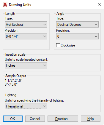
When you start a new drawing, decide what the length of one unit represents—an inch, a foot, a centimeter, a kilometer, or some other unit of length.
The UNITS command lets you control several unit display settings, including format (or type) and precision.
If you plan to work in feet and inches, use the UNITS command to set the unit type to Architectural, which displays the appropriate symbols when you specify object length in inches. If you plan to use metric units, leave the unit type set to Decimal.
Tip: Create your drawings at full size (1:1 scale). Later, when you create the layout, you'll specify the scale for printing a drawing on a standard-sized specified sheet.
The UCS, or user coordinate system icon, shows you the direction of the Cartesian coordinate system axes.
The UCS defines:
By default, the UCS icon appears in the lower left corner of the drawing window. Watch this video to understand more UCS basics.
Transcript
00:03
The UCS icon, or User Coordinate System icon, shows you the direction of the Cartesian coordinate system axis.
00:11
By default, the UCS icon appears in the lower left corner of the Drawing window.
00:17
The UCS icon indicates the direction of the X and Y axes.
00:22
By default, the UCS icon appears white, but you can change its appearance to be color-coded with the X axis shown in red,
00:30
and the Y axis shown in green.
00:33
You can control the display of the UCS icon using tools on the View ribbon, in the Coordinates panel,
00:39
or by right-clicking on the UCS icon itself.
00:43
If you do not see the Coordinates panel on the View ribbon,
00:46
with the view ribbon selected, right-click any tab in the ribbon
00:50
and choose Show Panels Coordinates, to toggle on the Coordinates panel.
00:57
In the Coordinates panel, you can control the display of the UCS icon.
01:02
When you choose Show UCS icon at origin, the UCS icon will always appear at the origin, which is the 00 coordinate location.
01:12
When this option is selected, if you pan the drawing,
01:16
the UCS icon moves because the origin (the 00 coordinate location) has also moved.
01:23
If the grid display is toggled on, you can see that the UCS icon is located at the origin,
01:29
because the icon aligns with the red X axis, and the green Y axis.
01:36
If you pan the drawing so that the corner is no longer on the screen, the UCS icon goes back to the lower left corner.
01:45
With the grid visible, you can see that the UCS icon no longer aligns with the X and Y axes.
01:54
If you choose Show UCS icon, the icon will always remain in the lower left corner of the drawing,
02:01
regardless of where the origin is actually located.
02:04
So, as you pan the drawing, the UCS icon stays in the lower left corner.
02:10
With the grid display toggled on, you can see the X and Y axes, as indicated by the red and green grid lines respectively,
02:18
and you immediately see that the UCS icon is not located at the origin.
02:24
You can also control this setting by right-clicking the UCS icon itself.
02:29
When you right-click the UCS icon, and expand the UCS Icon Settings option in the shortcut menu,
02:35
you can see that the Show UCS icon at Origin option is currently not selected.
02:41
When you click this option to toggle it on, the UCS icon immediately returns to the origin.
02:48
In the Coordinates panel of the View ribbon, you can also choose Hide UCS icon, in which case the UCS icon is no longer visible.
02:59
These settings are saved with the drawing file, and the changes you make to these settings only affect the current drawing.
03:06
You can also adjust other properties of the UCS icon, such as the icon style, line width, size, and color.
03:16
To adjust these properties, you can click the UCS Icon Properties button in the Coordinates panel of the View ribbon,
03:25
or right-click the UCS icon and choose UCS Icon Settings Properties.
03:32
AutoCAD LT displays the UCS icon dialog.
03:37
By default, the program displays a 3D style icon, but the axes are white.
03:43
That is because the Apply Single Color checkbox is selected.
03:47
If you clear this checkbox, the program displays a 3D style icon with colored axes (red for the X axis, and green for the Y axis).
03:58
When the Apply Single Color checkbox is selected, you can choose the color of the UCS icon when it appears in model space.
04:07
When displayed using the 3D style, you can increase the line width of the UCS icon.
04:14
If you prefer, you can switch the icon to a 2D style, in which case the UCS icon will look a bit different.
04:23
To change the style of the UCS icon, enter a different value or drag the slider.
04:31
The default UCS icon size is 50.
04:36
You can also change the color of the UCS icon that appears in layout tabs when working in paper space.
04:43
The default color is AutoCAD Index color 160, which is a shade of dark blue.
04:49
The changes you make in the UCS icon dialogue are saved as part of the AutoCAD LT Environment,
04:56
and remain in effect for all drawings.
Video transcript
00:03
The UCS icon, or User Coordinate System icon, shows you the direction of the Cartesian coordinate system axis.
00:11
By default, the UCS icon appears in the lower left corner of the Drawing window.
00:17
The UCS icon indicates the direction of the X and Y axes.
00:22
By default, the UCS icon appears white, but you can change its appearance to be color-coded with the X axis shown in red,
00:30
and the Y axis shown in green.
00:33
You can control the display of the UCS icon using tools on the View ribbon, in the Coordinates panel,
00:39
or by right-clicking on the UCS icon itself.
00:43
If you do not see the Coordinates panel on the View ribbon,
00:46
with the view ribbon selected, right-click any tab in the ribbon
00:50
and choose Show Panels Coordinates, to toggle on the Coordinates panel.
00:57
In the Coordinates panel, you can control the display of the UCS icon.
01:02
When you choose Show UCS icon at origin, the UCS icon will always appear at the origin, which is the 00 coordinate location.
01:12
When this option is selected, if you pan the drawing,
01:16
the UCS icon moves because the origin (the 00 coordinate location) has also moved.
01:23
If the grid display is toggled on, you can see that the UCS icon is located at the origin,
01:29
because the icon aligns with the red X axis, and the green Y axis.
01:36
If you pan the drawing so that the corner is no longer on the screen, the UCS icon goes back to the lower left corner.
01:45
With the grid visible, you can see that the UCS icon no longer aligns with the X and Y axes.
01:54
If you choose Show UCS icon, the icon will always remain in the lower left corner of the drawing,
02:01
regardless of where the origin is actually located.
02:04
So, as you pan the drawing, the UCS icon stays in the lower left corner.
02:10
With the grid display toggled on, you can see the X and Y axes, as indicated by the red and green grid lines respectively,
02:18
and you immediately see that the UCS icon is not located at the origin.
02:24
You can also control this setting by right-clicking the UCS icon itself.
02:29
When you right-click the UCS icon, and expand the UCS Icon Settings option in the shortcut menu,
02:35
you can see that the Show UCS icon at Origin option is currently not selected.
02:41
When you click this option to toggle it on, the UCS icon immediately returns to the origin.
02:48
In the Coordinates panel of the View ribbon, you can also choose Hide UCS icon, in which case the UCS icon is no longer visible.
02:59
These settings are saved with the drawing file, and the changes you make to these settings only affect the current drawing.
03:06
You can also adjust other properties of the UCS icon, such as the icon style, line width, size, and color.
03:16
To adjust these properties, you can click the UCS Icon Properties button in the Coordinates panel of the View ribbon,
03:25
or right-click the UCS icon and choose UCS Icon Settings Properties.
03:32
AutoCAD LT displays the UCS icon dialog.
03:37
By default, the program displays a 3D style icon, but the axes are white.
03:43
That is because the Apply Single Color checkbox is selected.
03:47
If you clear this checkbox, the program displays a 3D style icon with colored axes (red for the X axis, and green for the Y axis).
03:58
When the Apply Single Color checkbox is selected, you can choose the color of the UCS icon when it appears in model space.
04:07
When displayed using the 3D style, you can increase the line width of the UCS icon.
04:14
If you prefer, you can switch the icon to a 2D style, in which case the UCS icon will look a bit different.
04:23
To change the style of the UCS icon, enter a different value or drag the slider.
04:31
The default UCS icon size is 50.
04:36
You can also change the color of the UCS icon that appears in layout tabs when working in paper space.
04:43
The default color is AutoCAD Index color 160, which is a shade of dark blue.
04:49
The changes you make in the UCS icon dialogue are saved as part of the AutoCAD LT Environment,
04:56
and remain in effect for all drawings.
Industry:
Architecture, Civil / Site development contractors, Site Development (General civil engineering), Finishing contractors, Building products and fabrication, Structural engineering, Building owners and operators, General contractors
Role:
Technical and engineering manager, Product engineer, Environmental Engineer
How to buy
Privacy | Do not sell or share my personal information | Cookie preferences | Report noncompliance | Terms of use | Legal | © 2025 Autodesk Inc. All rights reserved
Sign in for the best experience
Save your progress
Get access to courses
Receive personalized recommendations
May we collect and use your data?
Learn more about the Third Party Services we use and our Privacy Statement.May we collect and use your data to tailor your experience?
Explore the benefits of a customized experience by managing your privacy settings for this site or visit our Privacy Statement to learn more about your options.