& Construction

Integrated BIM tools, including Revit, AutoCAD, and Civil 3D
& Manufacturing

Professional CAD/CAM tools built on Inventor and AutoCAD

Integrated BIM tools, including Revit, AutoCAD, and Civil 3D

Professional CAD/CAM tools built on Inventor and AutoCAD
Connect inlets and outlets to a pond in a drainage system model.
Type:
Tutorial
Length:
5 min.
Tutorial resources
These downloadable resources will be used to complete this tutorial:
Transcript
00:03
Once you have designed a pond and incorporated it into a drainage system model,
00:08
you must properly connect it to the model.
00:11
This includes designing an inlet that connects it to upstream pipes
00:15
and an outlet that connects it to the discharge control point downstream.
00:20
He was a background image to position these pipes correctly.
00:24
So load the pond pipe dot D xf file into the cad data.
00:32
Make sure the snap tool is activated
00:34
in the planned ribbon.
00:36
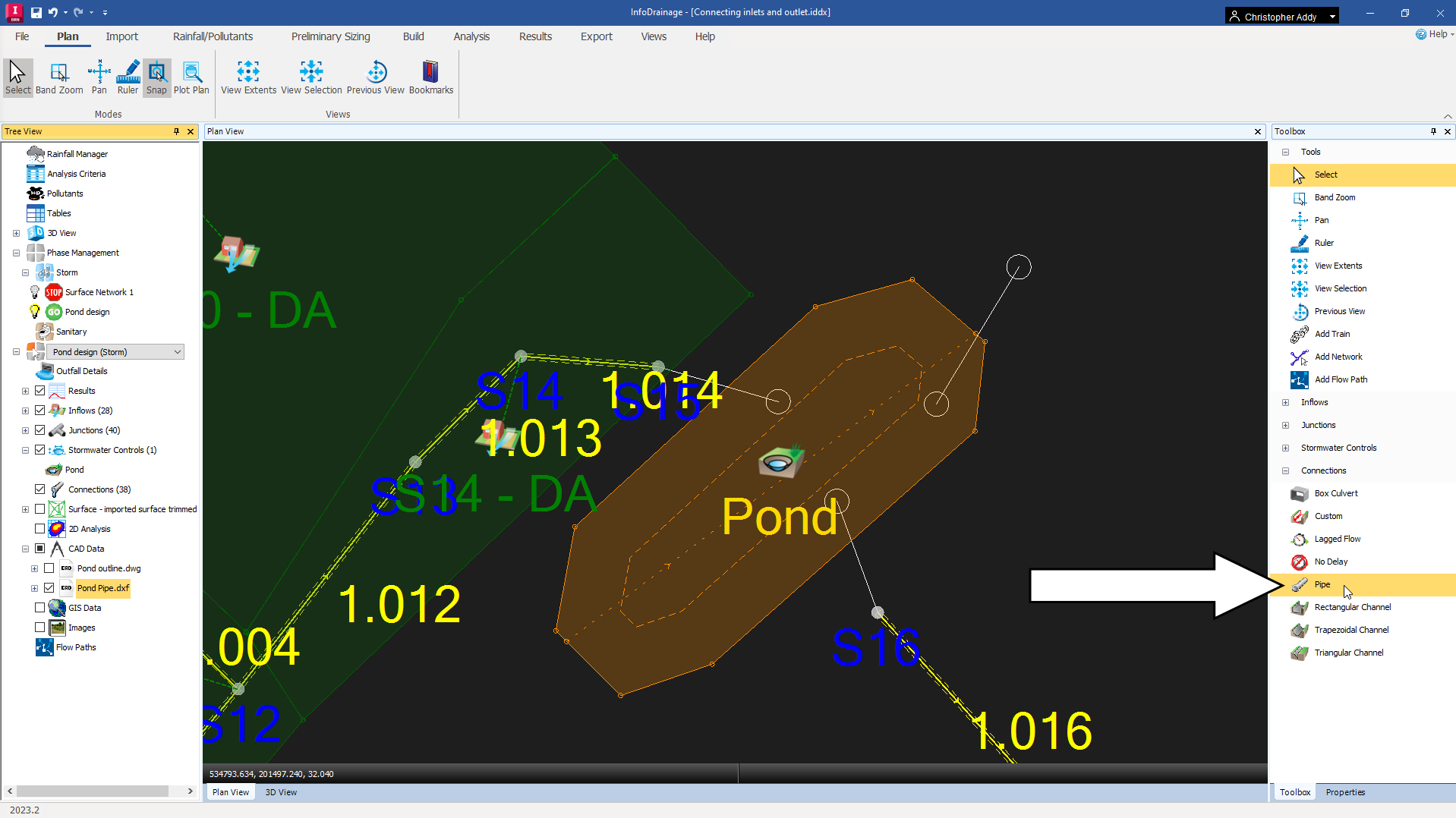
To start, you must first select a connection type
00:40
with a model open in the plan view,
00:42
navigate to the toolbox and expand the connections node.
00:46
Here there are several different connection types available.
00:50
Pipe is one of the most common connections used
00:53
so selected from the toolbox,
00:56
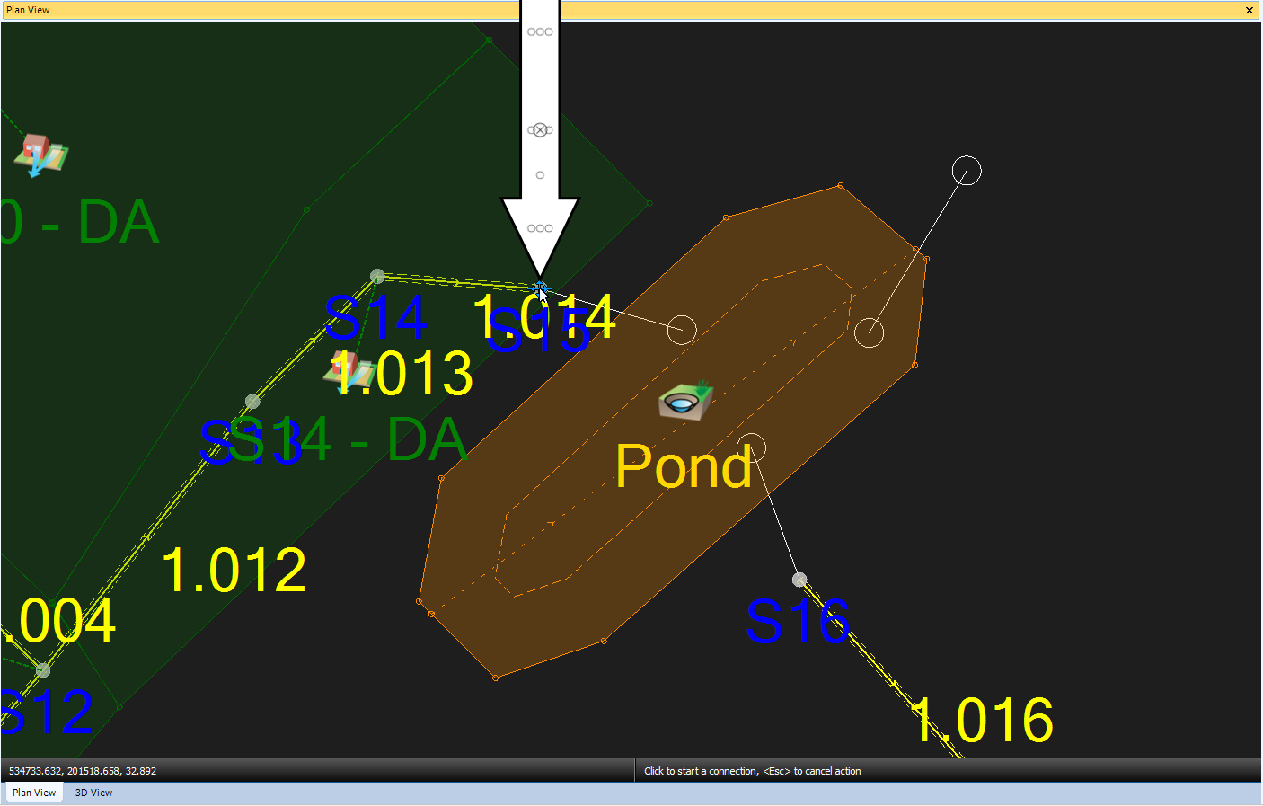
click and drag the pipe connection to anchor its start 0.2 manhole S. 15.
01:02
Then with the connection still attached to the cursor,
01:05
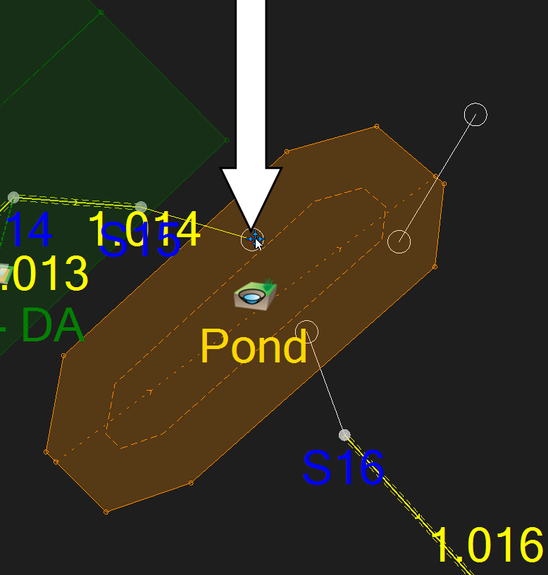
click again following the background image to place the connection endpoint,
01:10
you may need to zoom in to snap this correctly.
01:13
It is best practice to then reactivate the
01:15
select tool to avoid creating additional connections.
01:19
You can now double check this connections properties.
01:22
By double clicking the pond icon.
01:25
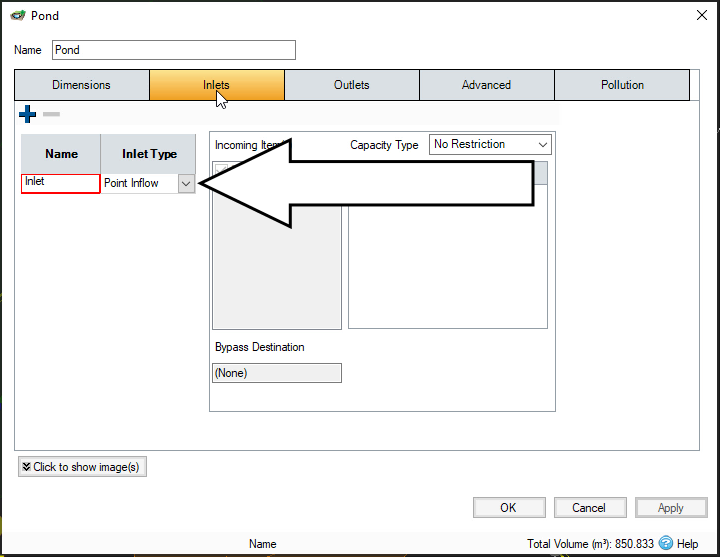
In the pond dialog select inlets.
01:28
The inlet type drop down is set to point in
01:31
flow by default for the single inlet you just created,
01:35
click ok
01:37
with the pond's inlet set,
01:39
it is now time to connect an outlet
01:42
again, click and drag the pipe connection to the pond,
01:45
making sure to drop the start point to snap to
01:48
the background image of the pipe leaving the pond.
01:51
Then
01:52
drag the end point to the receiving Manhole which is Manhole s. 16 in this example
01:59
notice that when you hover the cursor over the manhole icon,
02:02
it now presents contextual options for new
02:05
or inlet depending on the cursors location.
02:09
Situate the cursor so the manhole icon says inlet.
02:13
Then click again,
02:15
click the select tool from the toolbox before you continue working,
02:19
an outlet icon now appears in the pond.
02:23
Double click it to open its properties.
02:26
By default, the outlet type is set to free discharge,
02:30
expand the drop down menu to change it to an orifice.
02:34
You must now calculate the diameter of the orifice so that
02:38
it limits the discharge from the pond to 16.1 L per second
02:42
which was a value calculated earlier
02:46
in the pond dialog,
02:47
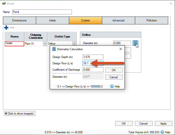
click the diameter calculator icon and set the design depth field to 1.675 m,
02:54
the maximum depth in the pond up to the free board level
02:58
and the design flow field to 16.1 liters per second.
03:03
Lead the coefficient of discharge set to 0.600. As it is in this example,
03:11
You will see the diameter field is grayed out with a value of 0.077 m.
03:18
Keep in mind that if you believe the diameter will be
03:21
small enough to be susceptible to blockages during rainfall events,
03:24
you may need to incorporate a cage or perhaps use a different control device,
03:30
click OK
03:32
Back in the pond, dialogue notice that the orifice diameter now displays as 0.077.
03:40
You must now provide diameters for the two pipes which were recently added
03:45
using the select tool.
03:47
Double click the pipe entering the pond.
03:50
The connections table opens
03:53
The pipe entering the pond is currently called pipe and the one leaving is pipe one
03:59
Set the Diameters for both pipes to 600.
04:03
And then click OK.
04:05
It is now time to make sure the pond is properly connected
04:08
to the rest of the drainage system,
04:11
navigate to the tree view.
04:13
Right, click the flow paths node
04:15
and select add
04:17
You could click any manhole upstream of the pond to
04:20
set a start point for a new flow path.
04:22
But for this example, select manhole? S. one
04:27
then
04:27
hover your cursor over the manhole. S. 17 downstream from the pond,
04:32
you will see the cursor turn green,
04:35
click the manhole to set the new flow path which highlights in red.
04:40
Lastly
04:41
you can check the profile view of the new flow path to see if there are any errors
04:47
in the tree view, expand the flow paths node and right click flow path,
04:51
then select show profile.
04:54
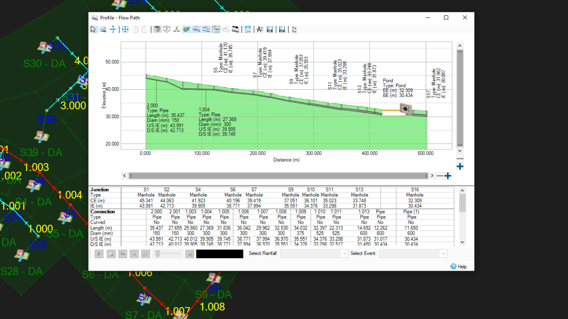
This opens the profile flow path dialog which displays the flow
04:58
paths elevation in relation to its start and end points.
05:03
The profile also shows the ponds inlets and outlets.
05:08
When you're finished with your review.
05:10
Close the dialog
Video transcript
00:03
Once you have designed a pond and incorporated it into a drainage system model,
00:08
you must properly connect it to the model.
00:11
This includes designing an inlet that connects it to upstream pipes
00:15
and an outlet that connects it to the discharge control point downstream.
00:20
He was a background image to position these pipes correctly.
00:24
So load the pond pipe dot D xf file into the cad data.
00:32
Make sure the snap tool is activated
00:34
in the planned ribbon.
00:36
To start, you must first select a connection type
00:40
with a model open in the plan view,
00:42
navigate to the toolbox and expand the connections node.
00:46
Here there are several different connection types available.
00:50
Pipe is one of the most common connections used
00:53
so selected from the toolbox,
00:56
click and drag the pipe connection to anchor its start 0.2 manhole S. 15.
01:02
Then with the connection still attached to the cursor,
01:05
click again following the background image to place the connection endpoint,
01:10
you may need to zoom in to snap this correctly.
01:13
It is best practice to then reactivate the
01:15
select tool to avoid creating additional connections.
01:19
You can now double check this connections properties.
01:22
By double clicking the pond icon.
01:25
In the pond dialog select inlets.
01:28
The inlet type drop down is set to point in
01:31
flow by default for the single inlet you just created,
01:35
click ok
01:37
with the pond's inlet set,
01:39
it is now time to connect an outlet
01:42
again, click and drag the pipe connection to the pond,
01:45
making sure to drop the start point to snap to
01:48
the background image of the pipe leaving the pond.
01:51
Then
01:52
drag the end point to the receiving Manhole which is Manhole s. 16 in this example
01:59
notice that when you hover the cursor over the manhole icon,
02:02
it now presents contextual options for new
02:05
or inlet depending on the cursors location.
02:09
Situate the cursor so the manhole icon says inlet.
02:13
Then click again,
02:15
click the select tool from the toolbox before you continue working,
02:19
an outlet icon now appears in the pond.
02:23
Double click it to open its properties.
02:26
By default, the outlet type is set to free discharge,
02:30
expand the drop down menu to change it to an orifice.
02:34
You must now calculate the diameter of the orifice so that
02:38
it limits the discharge from the pond to 16.1 L per second
02:42
which was a value calculated earlier
02:46
in the pond dialog,
02:47
click the diameter calculator icon and set the design depth field to 1.675 m,
02:54
the maximum depth in the pond up to the free board level
02:58
and the design flow field to 16.1 liters per second.
03:03
Lead the coefficient of discharge set to 0.600. As it is in this example,
03:11
You will see the diameter field is grayed out with a value of 0.077 m.
03:18
Keep in mind that if you believe the diameter will be
03:21
small enough to be susceptible to blockages during rainfall events,
03:24
you may need to incorporate a cage or perhaps use a different control device,
03:30
click OK
03:32
Back in the pond, dialogue notice that the orifice diameter now displays as 0.077.
03:40
You must now provide diameters for the two pipes which were recently added
03:45
using the select tool.
03:47
Double click the pipe entering the pond.
03:50
The connections table opens
03:53
The pipe entering the pond is currently called pipe and the one leaving is pipe one
03:59
Set the Diameters for both pipes to 600.
04:03
And then click OK.
04:05
It is now time to make sure the pond is properly connected
04:08
to the rest of the drainage system,
04:11
navigate to the tree view.
04:13
Right, click the flow paths node
04:15
and select add
04:17
You could click any manhole upstream of the pond to
04:20
set a start point for a new flow path.
04:22
But for this example, select manhole? S. one
04:27
then
04:27
hover your cursor over the manhole. S. 17 downstream from the pond,
04:32
you will see the cursor turn green,
04:35
click the manhole to set the new flow path which highlights in red.
04:40
Lastly
04:41
you can check the profile view of the new flow path to see if there are any errors
04:47
in the tree view, expand the flow paths node and right click flow path,
04:51
then select show profile.
04:54
This opens the profile flow path dialog which displays the flow
04:58
paths elevation in relation to its start and end points.
05:03
The profile also shows the ponds inlets and outlets.
05:08
When you're finished with your review.
05:10
Close the dialog
Once a pond design has been incorporated into a drainage system model, it must be properly connected to the model. This includes designing an inlet that connects it to upstream pipes and an outlet that connects it to the discharge control point downstream.
First, create the inlet connection.
Once the inlet of the pond is set, connect an outlet.
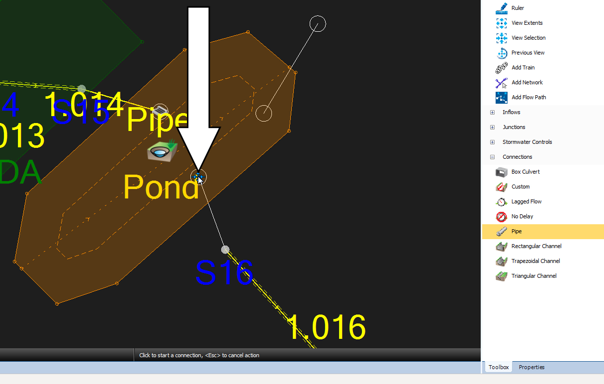
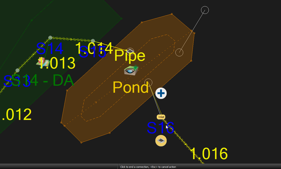
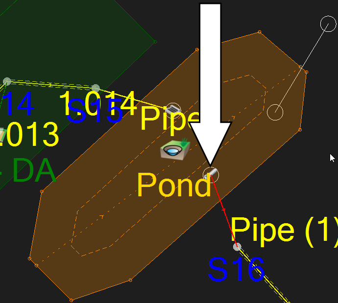
To calculate the diameter of the orifice, so that it limits the discharge from the pond to 16.1 l/s:
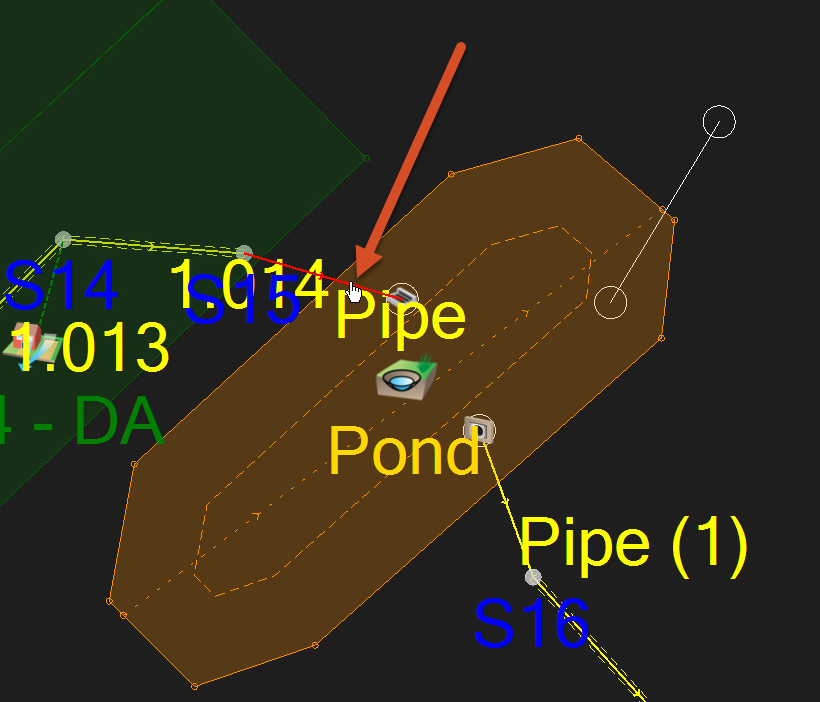
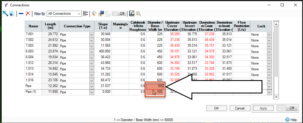
To make sure the pond is properly connected to the rest of the drainage system, check the flow path.
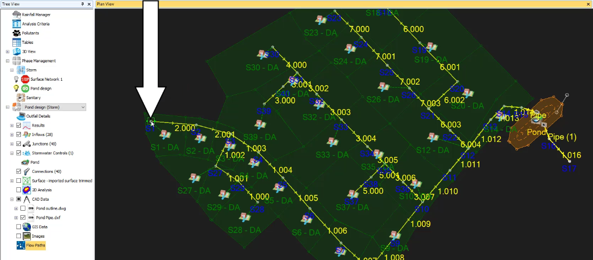
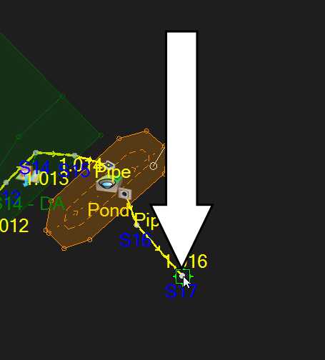
Note: the flow path is highlighted in the model and its path runs through the inlet and outlet created in the pond.

How to buy
Privacy | Do not sell or share my personal information | Cookie preferences | Report noncompliance | Terms of use | Legal | © 2025 Autodesk Inc. All rights reserved
Sign in for the best experience
Save your progress
Get access to courses
Receive personalized recommendations
May we collect and use your data?
Learn more about the Third Party Services we use and our Privacy Statement.May we collect and use your data to tailor your experience?
Explore the benefits of a customized experience by managing your privacy settings for this site or visit our Privacy Statement to learn more about your options.