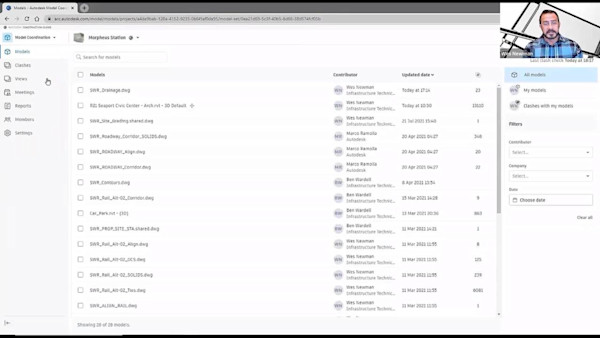
Description
Key Learnings
- Learn about solving the challenges of combining Revit and AutoCAD Plant 3D workflows.
- Learn how to implement cloud-based collaboration workflows for design and coordination.
- Learn about integrating building and industrial piping design for issue management.
- Learn about connecting design and construction.
Speakers
- Jose ArizaJose Ariza joined Autodesk in 2017. He works as a Technical Sales Specialist for EMEA focusing on Autodesk’s building and construction portfolio. Before joining Autodesk, Jose had worked as a BIM consultant freelancer and also as a BIM Manager for a Spanish Autodesk Partner. As a result, for more than 8 years so far Jose has helped the main companies in the AEC sector during the BIM implementation process and in the development of both national and international interdisciplinary projects using Autodesk technology. Moreover, he has collaborated with the University of Córdoba (Spain) as Associate Professor. Born in Córdoba, Jose holds a BSc in Technical Industrial Engineering and a MD in Architectural and Engineering Layout Techniques and Design Methods from the University of Córdoba. When he's not installing a new version of Autodesk products, Jose spends his free time playing football, karting and watching series and MotoGP, as he's a bike lover.
- Alexandre Mihalache CotreantiMy role is Senior Technical Solution Executive in the European AEC technical specialists team at Autodesk. I'm based in France and have a structural engineering background. Over the last years, I have worked with structural analysis, collaboration for the AEC sector, as well as Plant design. I help spreading the Autodesk BIM and collaboration vision for both Autodesk partners and customers.
JOSE ARIZA: Welcome to the session about how to collaborate like a Pro using Revit and Plant 3D in the cloud. It's really a pleasure to be part of Autodesk University again.
Before starting, we need to share the safe harbor statement. As this is a recording, we highly recommend you pause the video and take your time to read it before continuing.
My name is Jose Ariza. I'm a mechanical engineer, and I have been with Autodesk for more than five years as technical sales specialist, focused on cloud collaboration and digital transformation for different industry segments in EMEA. I have the honor to co-present this session with my colleague and friend, Alexandre Mihalache. Do you mind to introduce yourself?
ALEXANDRE MIHALACHE: Hi. thanks a lot, Jose. My name is Alexandre Mihalache. I have a structural engineering background. And I've been with Autodesk for 14 years now. Just like Jose, I'm part of the technical specialist team, and I'm based in Paris. Through the years I've been working on structural design, industrial piping, and cloud collaboration.
JOSE ARIZA: Thanks, Alex. We have a very ambitious agenda to really build up your confidence, to improve your performance and collaboration skills for industrial plant projects. We will start with an introduction to set some fundamentals about what is Revit, Plant 3D, and Autodesk Construction Cloud. We will continue with design collaboration workflows, where we are going to explain how to properly work and collaborate with the design solutions in the cloud. And last, but not least, we will end talking about how to leverage the cloud to speed up your coordination workflows and issue management activities.
Let's start then with the introduction. What is Revit and Plant 3D? This is a question you might already know, but we want to make sure we are on the same page and really understand what each solution does. Plant 3D is the solution for design and layout of process plant facilities.
Plant 3D uses a spec-driving technology and standard parts catalogs. You can create [INAUDIBLE] quickly from industry standard symbol libraries, use data validation to quickly identify possible errors, create and edit an accurate 3D model for process piping, and customize equipment to fit many process applications. And using a fully database environment where we can generate reports, list, and bill of material in seconds, and automate the creation of isometrics and orthographic drawings in order to produce [INAUDIBLE] deliverables.
On the other hand, Revit is a multidisciplinary solution that allows to work in a full database, file-centric, and parametric environment, bringing architects, structural engineers, MEP engineers, designers, and contractors to work together in the same construction project. All the documentation is created quickly with sections, views, and schedules generated automatically, all of them coming from the 3D BIM model. All the changes are automatically propagated to all the documentation.
But why we need to collaborate with Revit and Plant 3D? Well, this is a very common question from customers. And the answer is that we need to use the right solution for the right discipline and coordinate the overall industrial plant design. Plant 3D is the right solution for all the process piping and equipment, while Revit will help with all the structural regular MEP and architectural design. Building up collaboration between these two solutions will allow us to work without silos across the different project disciplines.
Now, Alex will continue talking about Autodesk Construction Cloud.
ALEXANDRE MIHALACHE: Thanks a lot, Jose. This section introduces the foundation of Autodesk Construction Cloud, which is the Common Data Environment, or CDE. Autodesk developed for a few years now a common data environment for all trades and people involved in the construction project. In this class, we will focus on the design and preconstruction phases of such a project.
Our common data environment connects all team members, whether they use Plant 3D, Revit, Navisworks or an open BIM exchange format, such as IFC. Data can be managed and used with a desktop software, a web browser, Windows File Explorer, or eventually a mobile app.
Let's now put a name on the cloud solutions we will discuss in this session. The common data environment is Docs. Based on Docs, project members will organize and perform project collaboration and coordination using BIM Collaborate. Designers will use the Pro version of BIM Collaborate to co-author projects in Revit and Plant 3D. A BIM Collaborate Pro subscription comes with BIM Collaborate and Docs. A BIM Collaborate subscription comes with Docs.
We would like to provide a quick overview of the Docs main features here. The CDE Docs allows teams to control security, access, and provides different ways of sharing projects, such as models, documents, or markups. In order to collaborate, we need the proper setup first. We will discuss that in this section.
A hub is your company's space name on the Autodesk Cloud. This is where you create projects and new members, companies, or specific roles. The process can be manual or automated by using a template project previously created. Based on this, you can assign permissions to individuals, companies, or roles that can be also customized. Permission can be granted to access folders or to interact with data through issues, for example. We will discuss that later.
As a general guideline, for Plant 3D design settings, when you use Plant 3D for industrial piping projects, permissions to access 2D documentations or office documents, such as PDF, Excel, Word, is set up using the Docs module. To allow co-authoring, design teams will work with 3D models using the design collaboration module.
This video around co-authoring team management illustrates how to access the settings in the design collaboration module. This allows us to create and manage the design teams. In a team, we can assign permissions and set up its specific working folders. Permissions are assigned by individuals, groups, or companies, of course. In this case, we selected the 3D model's Plant subfolder as the team's working folder, as you can see here.
This is another example of how to set up Plant and Revit to work together with the cloud. Let's take a look. This shows how to start cloud collaboration in Revit. And it's a two-step process. First, I will create a publishing set to select the content we would like to publish to the cloud. The published views and sheets will be the only data that will be visible to a web browser or the mobile app.
The second step is to initiate cloud collaboration, which saves the central model to a specific project or new hub, like the EMEA collab district, the ACC projects that we show in this video. Once synchronized, it can be used by all the users on the local machine.
In Plant 3D, the cloud collaboration initiation is very similar to the Revit one. Using the Collaboration tab and the Share Project command, the project will be saved to the root of your Docs project. Should you need to save the master plant project to a specific subfolder of your Docs project, you can move it once uploaded. This will be useful if you've created a team's folder structure before initiating cloud collaboration. As you can see here, the Plant Project folder comes at the root, and we can easily move it to the correct work in progress design collaboration folder in the specific table.
Once the cloud plant project has been moved, use the design collaboration module to specify the 3D design folder to be used for a specific theme. This way the cloud system will only parse and consider these folders in the design collaboration module. It will disregard the many other files, such as the XML or specs, included in the plant project. This will show you the steps of selecting the folders and pointing at them to force the system to consider only the relevant data, meaning the 3D models in the hierarchy of folders in a plant project.
Now the cloud space is ready let's talk about the day to day collaboration. After comparing server-based and cloud collaboration, we'll describe co-authoring in Revit, and then in the AutoCAD Plant 3D. Server-based collaboration using a Local Area Network, LAN, or a Wide Area Network, WAN, has been available for a long time now. Users work locally and synchronize the data with the company servers.
For Plant 3D, it usually involves one or multiple SQL server instances hosting the master project, and for Revit, one or multiple servers hosting the central models as well. The cloud collaboration eliminates the need for servers and directly connects users' local models to the master central project on the cloud. Cloud co-authoring works with Revit, Plant 3D, and also with Civil 3D.
We'd like to take a moment to define a few basics about private cloud collaboration. This example shows a team working on the same models. When collaboration is initiated by user A, the Revit Cloud worksharing service automatically published two new versions of the central model to Docs. Users A, B, and C in this case can then work locally on this model and synchronize with the cloud central model, which creates new versions. These new versions are only visible in Revit.
Once the co-authoring team decides the work needs to be made available in the web browser interface for the other trades, one of its members will publish, which will create the version 3 in Docs. The team can also set up an automatic publishing, of course, using a predefined frequency.
Let's take a look at a short illustration on how to collaborate in Revit. The example prepared by Jose here is about an MEP, so a Mechanical Electrical Pumping model, in Revit, which is hosted on the cloud. When opened, the user will have his local model updated from the cloud automatically. And what we are showing here is how to link another model, a structural Revit model here directly from the project that is also on the cloud and in the team's space, in the team's work-in-progess space.
So the added value here, of course, is to have everything up to date, including the linked files, because they come from the common shared space on the cloud, on Autodesk Docs. As you can see, we illustrated here that the saved path is, of course, on the cloud, on Autodesk Docs. The last two steps, of course, are as usual when we're working with a workshop model to synchronize it. So basically to save the changes to the cloud to the central model. And of course, should we want to make it available for viewing in a web browser, we should always publish. Publishing is usually made in Revit 2023 directly from Revit.
The Revit Cloud worksharing service has been optimized for performance. Revit Cloud worksharing infrastructure brings cloud optimization and local cache optimization together. Cloud optimization is based on Amazon Web Services data centers. The geographically closest data center is used for caching data, which highly accelerates all the transfers-- data transfers, of course.
The local infrastructure is based on a process that runs on your computer. This process is called Revit Accelerator, as you can see it here. It uses two cache systems, the collaboration cache and the Personal Accelerator cache. When the user synchronizes, most of the data that has changed in the Revit model and its linked models has already been cached automatically using these two systems. Caching speeds up data transfers. This covers both changes made by the user and changes made by other users who synchronize their own local models with the cloud central model.
Let's now see why and how to use Plant 3D with the cloud. On the why side, cloud workflows are built on a service called collaboration for Plant 3D. This requires a BIM Collaborate Pro subscription. The collaboration for Plant 3D service is similar to the Revit Cloud worksharing service. It doesn't require servers or database replication as it used to do with a server-based workflow. Local collaboration cache uses a SQLite database, which is, by definition, lighter than the SQL server one.
Moreover, only the needed files use drawings. And their external references are downloaded locally. Collaboration for Plant 3D also allows admins to change settings while users are working on the project, which was just impossible with a server-based workflow. It also brings viewing the drawings on the models and, of course, the intelligence in those models, meaning the object properties. So it makes really easier to review the BIM data and all the data in the project, just by using a web browser or eventually the mobile app.
Interaction between local cache and cloud seems different from what we set for Revit. On the check out operation, the DWG is locked on the cloud and downloaded locally so the users can have write access in Plant 3D. A new version of that file is created locally. Other users can open the DWG read-only. On the check-in operation, the DWG is updated with the user's changes on the cloud, which creates a new version of that model, of course, and unlocks the file to be used by other users in Plant 3D. Revit doesn't really expose this to the user, but also applies a check-in, check-out system to work sets, for example.
To illustrate the check-in, check-out system, we have created an animation here. When user A first checks in a DWG drawing, version one is automatically published to Docs. To continue working on this file in Plant 3D, user A needs to check it out. User A can modify the drawing while it is locked for the users. Other users can open it read-only, as we said. Once user A finishes modifying the file, he or she checks it back in, which creates version 2 on Autodesk Docs, and makes it available for user B to check out. User B can now work on the DWG and check it back in to create version 3 on the cloud.
Let's now take a look at how co-authoring in Plant design works. On the left side, you have user A. The right side you have-- right-hand side, you have user B, who are working on the same project. The idea here is that user A would create a new drawing, and then link-attach the drawing that user B has opened on his computer on the right-hand side to continue drawing from that user B model.
He created the new drawing here and the Project Explorer shows that the model is only local. Then we use the collaboration attachment to attach user B model, user B DWG from the cloud directly from Autodesk Docs. Once this is done, user A will have to check it in, so save it to the cloud to make it available to the rest of the team. He can also keep it open on his own computer to continue working on it. So this is the check-in operation, which, of course, saves it locally and saves the changes that user A made on the cloud.
Now we are switching to user B. We would like to see changes made by user A, meaning the creation of the new drawing. So he just has to refresh his project that you can see in the project manager here. And the result, of course, is that the drawing user A just created appears. And we can read the status.
Going back to user A, he will start using the attachment file and start that routing pipe from specific equipment that user B owns in each drawing. Now we hit the problem here. User A hits a problem. The nozzle doesn't fit. So he asks user B to modify his model, which can be made simultaneously, of course. And user B here on the left-hand side of the screen can actually change the pressure glass and make it available by checking back the drawing to the cloud.
Once it's saved on the cloud, user A will have to download changes by refreshing his project from the cloud, again, using the project manager, which manages all design files, including P&IDs as well, of course, and specs. And then he can use the updated attachment to start routing the pipe directly from the attached equipment. You can observe that now the pipe has been automatically attached because it respects everything that has been set up before.
Now, back to user B, who could be working on his side, and this would be even simultaneous. User B will on the right-hand side here is adding a specific support to this pipe. And of course, Max's work available on the master project on the cloud by checking-- by just performing a check-in operation. Once this is done, user A, depending on the alerts that had been set up in Plant 3D, he would either refresh directly from the project browser or be alerted that the attached file has been changed. So he can easily refresh his file, and of course, see the impact of the changes made by the equipment owner, who is user B. As you can see it on the screen, we can now see the support in the attachment file.
So we would like to take a few minutes also to discuss best practices. So we call them dos and don'ts when working with cloud Plant 3D projects. Basically, as I said, use the project manager to manage all project files from within the Plant 3D. And when attaching XREFs, external references, use the PLANTATTACH command, not the regular classic AutoCAD XREF. Of course, check-in operations need to be done regularly. And if we don't intend to edit the drawings, just open them read-only, it's going to be lighter, of course.
On the don'ts side, our guidelines, I would say that is, of course, not to use the web browser to manage the project files and folders. We use the project settings, and do not use the File Explorer, the Windows File Explorer to change locally stored files or folders, of course. And as usual, with a cloud workflow, avoid working in an offline mode if possible.
In the next section, we will discuss how to manage cross-discipline collaboration. Let's talk a bit about fundamentals of design collaboration. So we will start with the work-in-progress space here, which is set up and driven by the Revit Cloud worksharing service. Every team, like in this example, the architectural team, piping team, and structure team has its own work-in-progress space. And they are working by synchronizing the Revit models with the central. And once team leads or BIM managers that you can see here as an architect team leader, MEP engineer, and the structural engineer decide that this work in Revit is ready for eventually internal review with an internet browser, they can then publish the latest work-in-progress models to Docs so they can review it.
And the next step would be to share it with the other trades. So this uses the design collaboration module and the shared space in Autodesk Docs. So when the team leads or team managers decide that these models are ready for sharing with other trades, they can actually create packages-- and we'll discuss that in a bit-- to share it. And of course, track the different shares that they performed on swim lines that will appear and will be discussed later. Once packages, once models have been shared, team leads or BIM managers will decide that they can be consumed. And the system will copy them in their own team space.
The design collaboration module we just mentioned is just essential to review design data and share it in an organized way. The online viewer allows to review and analyze aggregated models, even if they're not linked one to each other, and interact with the model's authors using the issues. We'll see that in a few moments. The package sharing system is great for organizing the sharing of BIM models, drawings, and Office documents. It brings a complete tracking solution for project managers and BIM managers.
Let's take a look at how to manage data exchange and the swim lines I just mentioned. Every team has a dedicated line for their own team. And the user's active line is the one at the bottom. Icons dynamically change feel. The feeling of the icons dynamically change depending on the teams viewing the information.
In this short video, you can see here the circles that are actually packages created by the team leads, and the squares that are just published models. So everything can be tracked. And this is the commands to create a package. That will be very useful for BIM managers.
In this example, we will illustrate the impact of sharing actions on files and folders. As you can see, everything works in its own space, own folder, with various-- with very diverse formats of files, Revit, Plant 3D, IFC, open BIM format. And the shared space is the place where packages are shared in Autodesk Docs.
You can see an example in the swim line here. Shared folders become visible to all of the teams [INAUDIBLE] in the project as around empty dot on the swim line. When a team consumes a package, the files are copied to its own space in the consumed folder. For example, here what we see on the swim line is that I'm part of the industrial plant. And I can see the architecture team has shared two packages that I did not consume because they are empty circles.
Let's take a look at cross-discipline collaboration, specifically at sharing packages and reviewing them. So to review the content of a team's aggregated model, as you see here, we can easily choose the models we would like to see and hit the Share Package button. We select the models, BIM, Revit, AutoCAD Plant 3D drawings, or IFC models, for example, even documentation to include in the package, name this package, and share it with the other trades, the other teams. So this is how it works. And it will show on the swim line.
To review a package, it's quite easy. You just have to navigate, click on the package that another team has shared with you, and then decide which models you are reviewing. The nice thing here is, of course, that models are intelligent, meaning that we can see properties of the different objects. You can see a structure of gun here, but we can see pipes, and of course any IFCs and their included objects.
We can also analyze changes. And we can actually prepare for that, meaning that we can easily select a specific team, point at a specific model, and control the changes that are shared with us by the trade that owns that model. This example shows a DWG Plant 3D file. And we are watching-- we are creating a watch group, what we call a watch group, on a specific pipeline, the line number 123 here.
Once we created the watch group, we will then be able to control it, maybe even to change it, to manage it directly from within the design collaboration module. If that trade modifies this specific object or group of objects in Plant 3D, or Revit, or any other solution that handles IFC, for example, we can easily see the changes because we just created this watch group. And we have a very nice alert here in the design collaboration module telling us that the watch group has changed.
So the system performs the analysis for us on this specific line. This works like a filter because changes can be multiple on projects and models can be very complex. So I can see now a comparison between the two versions. And I can really understand, including the properties of an object. I can really understand what happened between a version and the previous one.
Now, let's discuss concurrent cross-discipline design. We analyzed multiple workflows and selected the ones that seemed the more relevant to us. To use Plant 3D models in Revit, we can actually export them as coordination NWC files, which is a Navisworks cache format. The export can be done within Navisworks, or as we show it on this slide, directly from Plant 3D, if the export utility is installed.
The export can be local or to the cloud if Desktop Connector is used. The model can then be linked or imported in Revit as a coordination model. The same file formats can be used to export models from Revit to Plant 3D if the export utility is installed. In Plant 3D, the file can be attached as an external reference coordination model.
Let's see how it works with the NWC file in Revit. When my Revit model is open, I can easily attach an NWC file using the classic insert command, a link, or attached, of course, link or import directly from the cloud, from, for example, a shared folder. As you can see, the Plant 3D NWC model comes in and can be used to model in Revit. It's very useful to model around all the equipment and industrial piping that has been designed in Plant. And the models are also visible on deliverables.
On the Plant 3D side, as I have the Plant 3D model open here, I can actually just use the classic XREF command and attach a coordination model, an NWC model that was exported from Revit. I can go ahead and just point at the specific cloud folder that the Revit exported model is in, and then I can easily attach it here in a Plant 3D model and do exactly the same like in Revit, meaning modeling in Plant 3D around this Revit input.
It's also possible to export Plant 3D models to an IFC format using two existing external apps available on the Autodesk app store. So this covers the export from Plant 3D to Revit, of course. As an example, we share here a few screenshots of the export process in Plant, and the result of importing the IFC files in Revit. Of course, the advantage of this method is to have intelligent models in Revit that contain, if there were maps and correctly mapped, that contain a lot of properties that can be read and used directly in Revit.
So we prepared a short summary table for you that summarized the linked file formats when we are linking Plant 3D files in Revit. The bottom one, DWG, which is the AutoCAD plain format, has not been discussed yet, but we thought it was important to add it here as a guideline. Basically, the most important thing to say here-- and I won't go through all the text-- will be to look at the work-in-progress design use case column. Basically, should you want to link a Plant 3D model in Revit with object intelligence, object details, and object properties, we recommend to use the IFC export, which is an external add-in-- two external add-ins available, actually.
And should you just want to link the Plant 3D model as a global model, which will come as a block in Revit, we can use the NWC or DWG format. The NWC will have a lower impact on the Revit performance, and the DWG will have a higher impact, of course, on that Revit performance. The advantage of the DWG is that Revit models will show on the deliverables, which are Auto drawings in Plant 3D.
The other way around from Revit to Plant 3D, we recommend to format NWC and the plain AutoCAD DWG. The difference between those two methodologies, which are similar in terms of linking the model globally, just like as a block, the main difference will be for the deliverables, that if you use the DWG, the Revit models will show on the Auto drawings.
Should you want to use Revit or 3D piping, there is a solution. The solution is called Revit P&ID modeler. And using this kind of workflow needs some conditions to be respected. We need to use Plant 3D to create the P&IDs. And the Plant 3D projects need to be cloud projects, cloud workshare projects, so meaning that we need a BIM Collaborate Pro license.
This workflow will not allow you natively to generate isometric drawings. And eventually, it will cover the case if you have or are willing to create Revit piping content, because Revit piping content is not very rich natively, so it might require quite a large effort to be customized.
Let's now take a look at how this would work. So this is a cloud share AutoCAD Plant 3D project, which is a condition to use this kind of workflow again. I'm in Plant 3D, and this is the cloud P&ID drawing to be used in Revit. We just check it out. Now we know the vocabulary. Just look at these element properties, meaning the tag and all the elements on the Plant 3D P&ID.
The P&ID drawing can be viewed in a web browser interface. This is one of the advantages I was talking about earlier in this session. Object properties can also be reviewed, even on P&IDs, of course. And the cloud P&ID drawing can be accessed from Revit using the P&ID modeler, which is located in the System tab for Revit 2023. Now, this example was made with BIM 360, but it works also with Autodesk Docs, of course.
In this section, we are showing some system-type mapping, object mapping between the P&ID properties and the Revit content, the Revit families. So this has to be made properly. P&ID equipment and pipe accessories, tag properties can also be mapped with some Revit properties. That can be mapped through a shared parameters file. And we have a preview shared parameters on the cloud that you can discover in the handout of the session.
The P&ID drawing line is then linked into the Revit model and can be navigated like you can see here in the video. And for this example, the equipment called static mixer is the starting point of the pipe routing. As you can see, the right-hand side window shows us the full line, the full pipeline with the pipe segments and the inline accessories.
The Revit system type is chosen accordingly to the mapping with the P&ID service that we have just seen in the P&ID modeler settings. A color code is available and shows the status of the element in the P&ID line list. Revit checks if the element exists in 3D and will show it, and if the properties match. if they do, the status will be green.
We will move on and add an instrument to this pipe segment directly in Revit. [INAUDIBLE] design another branch from the equipment. Once this is done, we can add other in-line systems. If properties are not matched, the status will show a yellow-green warning, as you can see it, meaning that the object is on the P&ID line list, has been placed in 3D, but properties don't match.
Now, what happens if we modify a property in Plant 3D on the original P&ID drawing? We just, for example, modified a specific property, changed the number. We will update the P&ID drawing on the cloud. We can use a version comparison that's available in Autodesk Docs. We can see the differences.
And we can also update the properties as the properties are mapped via the shared parameter file, which can be local or cloud, again, with the preview shared parameter system that we described in the handout. This property will be also updated in Revit. And now the element in the line list changed color, which means everything is fine. And the valve tag has been updated accordingly.
The next section will be presented by my friend Jose and is usually integrated in the design process and the preconstruction phase.
JOSE ARIZA: Thanks, Alex. Let's talk about a hot topic, coordination and issue management. They are definitely very important topics for industrial plants, as these type of projects are very complex with kilometer-long pipes, where savings from clash detection can reach up to 10% of the contract value, and just a single clash can cost more than $4,000.
I like to use analogies. And coordination is like checking for spelling and grammatical errors when we write a book, where different tools and skillsets are needed along the project lifecycle. I know this is the picture you might imagine when you talk about coordination. It makes sense, as Navisworks is the core of the typical coordination workflow. In this workflow, each subcontractor or consultant and trade team create their own models using different file formats, then they share those models with the BIM coordinator, who federates them as he acts as a single point of contact for all the design teams. The BIM manager or BIM coordinator analyzes the models for clashes, generates a first unfederated model with associated clash reports, and shares them with the design teams.
Discussions are held. And each team goes back to work to resolve the clashes that were assigned to them. This process gets repeated until the coordination issues are resolved. Yes, this process can work, but it's a very long process. Issues that could have been identified immediately are not seen until the coordination process happens. And if the design teams want to look at clashes [INAUDIBLE], they need to have Navisworks. And the most important thing, they need to have access to all the latest multi-discipline models.
We understand that this is far from being ideal. In this diagram, you might-- so this diagram might help you to visualize the complete coordination process and how it connects all the activities, from visualize, manage, resolve, and report clashes. Starting from the first steps of the process, design teams and trade contractors are already uploading their model to the CDE, sharing packages in design collaboration, as Alex already explained, where they can share and iterate their content.
[INAUDIBLE] coordination monitors coordination spaces and automatically analyzes them from clashes, and reports the result in a clash matrix for review and prioritization. A rule-based analysis with Navisworks for further analysis are needed, or not a specific project stage. So the division coordinator can decide if it's needed or not.
After prioritization, the BIM coordinator can assign issues downstream, monitor the status of the issues, of that class's status, automatize reporting by scheduling on a one-time basis, or recurring reports to be discussed during coordination meetings, and inform all the project stakeholders at any time. All the project members with access can leverage clash status and issue management capabilities to resolve conflicts quickly and efficiently in the design tool, like Revit or Plant 3D.
But what does automatic clash detection mean? It means that any project stakeholder can upload models to the common [INAUDIBLE] environment and have them clash check instantly. In other words, project team members can take responsibility for clash detection, speeding up the overall coordination process, and let the BIM coordinator focus on complicated clashes and oversee the process, rather than be the bottleneck.
As Alex already has explained, we have seen what happens between design collaboration and Docs, where every team has their own space to work and collaborate. We will have similar behavior with coordination with spaces, where we can create multiple coordination spaces, link to specific folders in Docs. Models that are loaded to those folders are automatically checked for clashes.
Now that we know more about the complete coordination workflow, let's explore the different phases. First, visualize. Coordination is a cycled task. So it's important to save as many time as possible in admin activities. Users can leverage what I like to call federated models to save a collection of models of interest and aggregate the models.
Views are useful, as they can be easily used and shared with other project members. They also enable project members to review clashes and issues for a small subset of data from a coordination space, like by system, by level, or by specific locations or areas. Revit files, DWG, IFC, and NWC models are supported for aggregated visualization.
Moving to the Manage phase. Prioritization is a key part of the workflow, as this will help focusing on what is important to be solved quickly. The clash matrix in every coordination space will improve our capacity to understand what is the current coordination situation, displaying a grid within all the clashes that have not yet been analyzed. The matrix can be filtered to adjust the models that are shown, and really focus on the models that we are interested on.
When we are managing clashes, users will be able to group them by any property from our selected primary model. These properties are automatically generated in the authoring tools, such as dimensions, or materials, or systems. For example, grouping by type size will help to prioritize clashes, where bigger pipes are involved that might have a bigger impact in the project. This provides users even more granular control when reviewing clashes.
Sometimes a clash can be ignored. For example, when a light fixture seems to clash with a ceiling, as we didn't the model the [? voice. ?] But it was an accepted modeling decision. So removing these clashes from your views will help you work through real problems more efficiently, and reduce noise from the coordination space.
Once a clash or clash group is determined to no longer need attention, you can mark them as not an issue, explaining why I moved them to the Closed tab. These clashes can easily become active later again if needed.
The other option is to create an issue to indicate that something in the design requires investigations. Issues can be created from specific clashes, using the Clashes panel, or [INAUDIBLE] on a model using the Issues panel. We can edit the issue details in the Issues panel, like the title, status, issue type, and issue subtypes, due date on all the data. You can also add custom fields, like priority. And the most important thing, we'll be able to assign the issue to a specific person or role.
Additionally, we can also add watchers that need to be informed about a particular issue, but they are not expected to contribute to its resolution. A screenshot of the model is attached to the issue when it's created. You can also add reference, such as photos, files, and comments. [INAUDIBLE], we'll receive an email notification with a link to the issue for quickly access, which accelerates the solution process.
When clashes are marked as an issue and are assigned to a project member, they are moved from the Active tab to the Assigned tab. Here project members can view issue details and track the changes being made to resolve the issues. Once you select an issue, you can change the status to move forward the resolution process, from open, pending, in review, to closed. This status will be visibly implemented, as you can see in the right picture.
It's important to note that cloud-based technology is not a replacement for traditional coordination technologies, like Navisworks. But instead, when we use in conjunction with one another, they complement each other and add value to the process. The value of this approach is that it only requires the intervention of clash detection experts and a specialized skillset and tools to handle only the most complicated coordination issues, and democratize access to clash action workflows. Now, BIM coordinators and other Navisworks users take advantage of the latest released files available in the cloud by opening them [INAUDIBLE] to run rule-based clash detection analysis.
With the coordination issues adding, Navisworks users can open, edit, and comment issues created from any ACC model, including design collaboration, model coordination, and Docs. Navisworks users also have the ability to create issues within Navisworks and push through to the ACC ecosystem, enabling all the team members to communicate with other stakeholders.
The most powerful workflow is the ability to open and append all supported model files for model coordination, dial it into Navisworks, then run rule-based cloud detection workflows, and create issues [INAUDIBLE] in Navisworks, as we have seen before in the cloud environment, using the same interface across either desktop or cloud platform.
Issues creating either ACC or Navisworks are automatically loaded when models are opened, enabling users to view all the issues assigned to their model sets for specific coordination spaces and [INAUDIBLE].
Once an issue has been addressed or created in Navisworks, users will see them in ACC, allowing real team communication between both environments and providing a single set of tools for model coordination.
ACC allows managing issues on a unified platform across the entire project lifecycle, bringing all the stakeholders to track design, coordination, quality, safety, and commissioning issues from the same issues across all the different models inside ACC, especially the ones we are explaining in this session, like Docs, model coordination, and design collaboration.
The next step, resolve. Before moving forward to the resolution phase, we really need to acknowledge the potential big number of issues that are created along the entire project lifecycle, making issue management a key part of the coordination workflow. All issues on your project are accessible in the Issues log. This might be challenging when we have a huge number of issues to manage. So that's why it's important to leverage metadata, like status, issue type, priority, or due date, for better organization.
We can leverage this metadata to filter and sort issues. This process will really make a change on how we manage issues, allowing us to focus on what is important and prioritize issues with better visibility.
Coordination meetings are a key part of the coordination workflow, where the wide variety of discipline must be coordinated to solve issues for being able to optimize costs and reduce rework. Of course, coordination meetings can be disconnected and a time-consuming activity when we need to involve a certain number of stakeholders, bring all the 2D documentation, 3D models, take notes, and follow up from previous meetings. So to avoid working in silos and being able to access all the relevant information from a single [INAUDIBLE], ACC includes the option to host and manage online meetings. This definitely will help to track all the commitments made, and centralize all the meetings' records.
Teams can create an agenda with the different topics to be discussed, which people must be involved, document decisions, like linked issues, and assign people to actions to be made, establishing clear accountability. Teams can simplify communications, sending email notification to all the attendees with the agenda or the meeting notes. The captured minutes can be exported to PDF and follow up meetings can be organized from 16 meetings and carry over all the topics. The meeting feature, unfortunately, is not included in Docs.
As we introduced before, the next step in the coordination workflow is to solve identified issues in the author and design tools. For Revit, we have the new Revit issues add-in that closes the loop between issues management in the Autodesk production cloud platform and the desktop-based solution, allowing Revit users to visualize or solve [INAUDIBLE] issues. This really provides a seamless close issue management process between model coordination, design review, and design authoring.
Issues are automatically loaded when the add-in is opened, including the associated models, enabling Revit users to view all the issues assigned to their model. When selecting an issue in the side panel, we automatically load the associated view and zoom in with the correct camera position. Now we can immediately start making changes and solve the design problem, like in this example that we need to adjust the cable tray position.
Once the issue is resolved, the user can change the issue status and add comments to report out the changes. Of course, after making some changes in the model, now we need to synchronize these changes with the other teammates and publish a new version of this model into the cloud, as we saw previously.
Unfortunately, we don't have a similar add-in for Plant 3D. But good news-- it's in the future roadmap. So for now we recommend to work with two screens, using in one screen ACC or Navisworks, to see the issues in context, and Plant 3D opened in the other screen to do changes in order to solve the issues. Something to highlight here is that we can keep using the switchback function between Navis and Plant 3D.
Last, but not least, report. I love football, so I couldn't imagine a better analogy for a traditional reporting process than a goalkeeper throwing away balls as reports to the design teams. This picture might look familiar for you if you are part of the coordination process where, you are working with a lot of different models, and manually create reports in Navisworks, then export them to Excel, and finally send them by email. In other words, dealing with a lot of admin work.
The way we share information during the project is an important differentiator on how effective and fast we are to solve problems. The report tool inside all the ACC models provide a central location to create, set up, schedule, and view on demand and schedule reports. ACC has the ability for types of configurable issue templates to start creating reports. During the setting process, we can filter by different criterias, like creation period, status, or even custom field, like [INAUDIBLE]. Reports can be set up in local language by project, for instance.
We can establish two types of reports-- on demand and scheduled reports. With on demand reports, we will be able to create and share an automatic report based on specific project requirements. This on demand report will be displayed in the list of reports for 30 days before expiring. We can save this on demand report as a template and do some basic setup to schedule and fully automate the report curation. The report tool is available in Docs, design collaboration, model coordination, and the insight model.
Let's see this example on our demand report, where the product manager needs to review all the issues identified as a priority 1 and 2 created during the month of August. We could do it from the report tool, but it's also possible [INAUDIBLE] from the Issues tab, filtering the issues, and select-- so filtering the issues based on the requirements, so priority and starting-- and created date, and then we can export the current list of issues as a PDF report.
Once the report is ready, we can download the report or share the available link with even external members. You can see here the report, which is fully interactive and contains direct hyperlinks for quick access to the cloud environment in ACC for further analysis.
For a scheduled report, it couldn't be easier. As I mentioned before, starting from a template, we just need to pick the current start and end date and assign recipients based on their name, company, and role. It can be even shared with non project users through email.
We are in the area of data. With no doubt, data is the new fuel that drives success in our industry. From the very beginning of this session, we started to talk about a common data environment. And since then, we have been explaining how to create and manage data inside ACC. Now is the time to explain a bit how we can leverage data to take better informed decisions and identify where we need to focus during the design phase.
The insight model inside ACC delivers unified product level data, analytics to help, getting you up to speed with what's going on in a project, displaying an overview of metrics related to your own company or team, using a cart like a list of your companies issues, charts with the evolution of coordination issues that allows you to identify trends and potential gaps or problems, all with quick access to important or frequent documents. Of course, you can customize your own dashboards based on your needs.
There are some project-level dashboards related to design, quality, and safety that we can use as a corporate project level. The Design dashboard provides insight into trends and patterns around design and coordination issues, and, of course, which companies are responsible for resolving them.
This session is coming to an end, so I would like to recap what we have shared about working in the cloud with Revit and Plant 3D. We have seen Autodesk Construction Cloud as the perfect solution to empower collaboration with Revit and Plant 3D through a cloud-based environment, ensuring that all users have access to the right information at the right time; avoiding version mistakes with automatic version control; having a common environment as the only [INAUDIBLE]; being accessible anywhere at any time; interacting with documents so you can quickly upload, download, block, and share them; using the version compare tool to understand which element has been changed, added, or removed for better decision making; having a complete traceability of each of the deliverables of the project between the different disciplines through the design collaboration model; collaborating in real-time with the design solutions for the cloud; increasing designers' productivity, analyzing, and viewing in context all the [INAUDIBLE] models [INAUDIBLE] in a web browser; accelerating the review process and democratizing access to the models; and, of course, our robust coordination and issue management workflow through automatic clash detection analysis that is connected with the design solution and Navisworks to drive efficiency on how we solve issues.
Thank you very much for your attention. If this session was interesting for you, please recommend the session. And the most important thing, please don't forget to check the session handout, as we have prepared a lot of material and extra information. Thank you very much.
Downloads
Tags
Product | |
Industries | |
Topics |